

Page 1

Pro-Stack Broadband Three Antenna
Phasing Relay Unit
Control Console
DXE-EC-PS3
DXE-EC-PS3-INS-Revision 1a
© DX Engineering 2017
1200 Southeast Ave. - Tallmadge, OH 44278 USA
Phone: (800) 777-0703 ∙ Tech Support and International: (330) 572-3200
Fax: (330) 572-3279 ∙ E-mail: [email protected]
- 1 -
Page 2

Introduction
The DXE-EC-PS3 is a custom made twelve position control console for the DXE-PS-3B or the
DXE-PS-3BDIN Pro-Stack Broadband Three Antenna Phasing Relay Unit.
The DXE-EC-PS3 offers the following features:
Stainless Steel Housing
Non-Skid feet
On-Off toggle switch
Green LED power on indicator
Twelve position manual switch
Filter capacitors on each control line
Internal automatic resettable fuse
Includes a 2.1 mm power plug for +12 Vdc power connection
Front and Rear Panels
On/Off toggle switch Control Wire Feed Through
Power ON Green LED Power
Connection
12 Position Rotary Switch
The DC Input used is +12 Vdc. A 2.1 mm power cord is supplied with unit. The wire with the white
stripes is the +12 Vdc.
Outer Connection is GROUND Center Pin is +12 VDC.
If station power is used, it must be +12 to +13.8 Vdc at 1 amp (fused) minimum.
Tools Required
Phillips Head Screwdriver
Wire Stripper
Small Flat Blade Screwdriver
Overall Size
- 2 -
Page 3
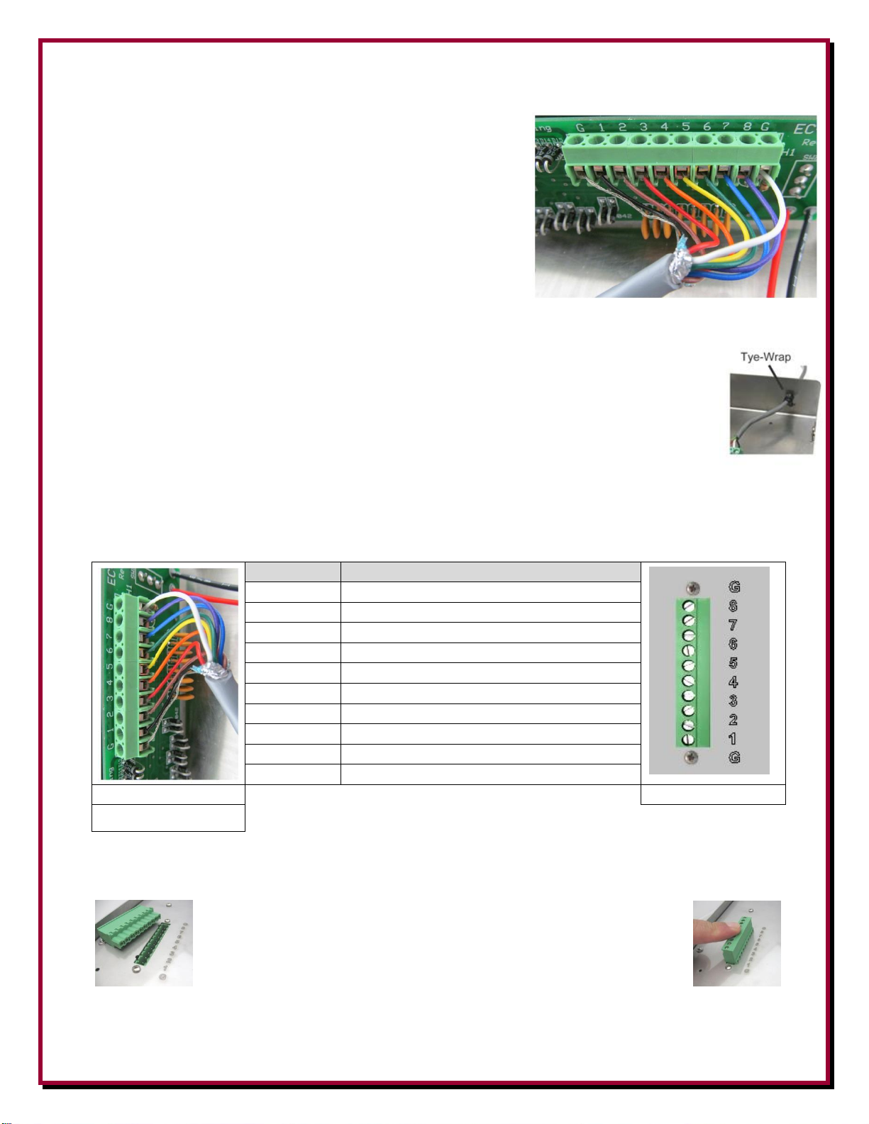
Interior Control Cable Connections
\
Connector
Control Wire Color
G
8 7 6
5 4 3
2 1 G
DXE-EC-PS3
DXE-PS-3B
(Your color code may vary
from the picture above)
1. Open the unit by removing the four (two per side) Phillips
head screws to remove the cover.
2. Push the end of the cable through the control wire feed
through on the rear of the unit.
3. Connections for the wire are made on the green header.
Loosen each terminal screw until it is near flush with the
top of the connector block.
4. Strip approximately 1/4" insulation from the wire end and
connect each wire to a terminal by sliding the wire completely into the wire connection hole.
Using a small flat blade screwdriver, tighten the associated screw until the wire is
firmly gripped in place as shown. (Your control wire color sequence may vary).
Take caution to ensure just the wire is clamped in place, not the wire's insulation which
would cause an open or intermittent connection. Do not over tighten the screw so much
that the wire is cut instead of being firmly gripped. Use a Ty-Wrap on the inside of the
unit to hold the cable from pulling outward as shown.
When connecting the control cable to the DX Engineering Pro-Stack Broadband Three Antenna
Phasing Relay Unit (DXE-PS-3B and DXE-PS-3BDIN), ensure your cable is wired the same way
at the other end to avoid un-necessary troubleshooting. Use the chart below to record which color
wire is connected to each terminal connection.
The green connector on the DX Engineering Pro-Stack Broadband Three Antenna Phasing Relay
Unit (DXE-PS-3B and DXE-PS-3BDIN) pulls straight off of the relay unit. Use a small
screwdriver to open each wire connection (same method as described
for the control console wire connections). Insert the stripped wire and
tighten. Do not allow insulation inside the connector which may
cause an open. When installing the green connector, push straight in
until fully seated.
- 3 -
Page 4
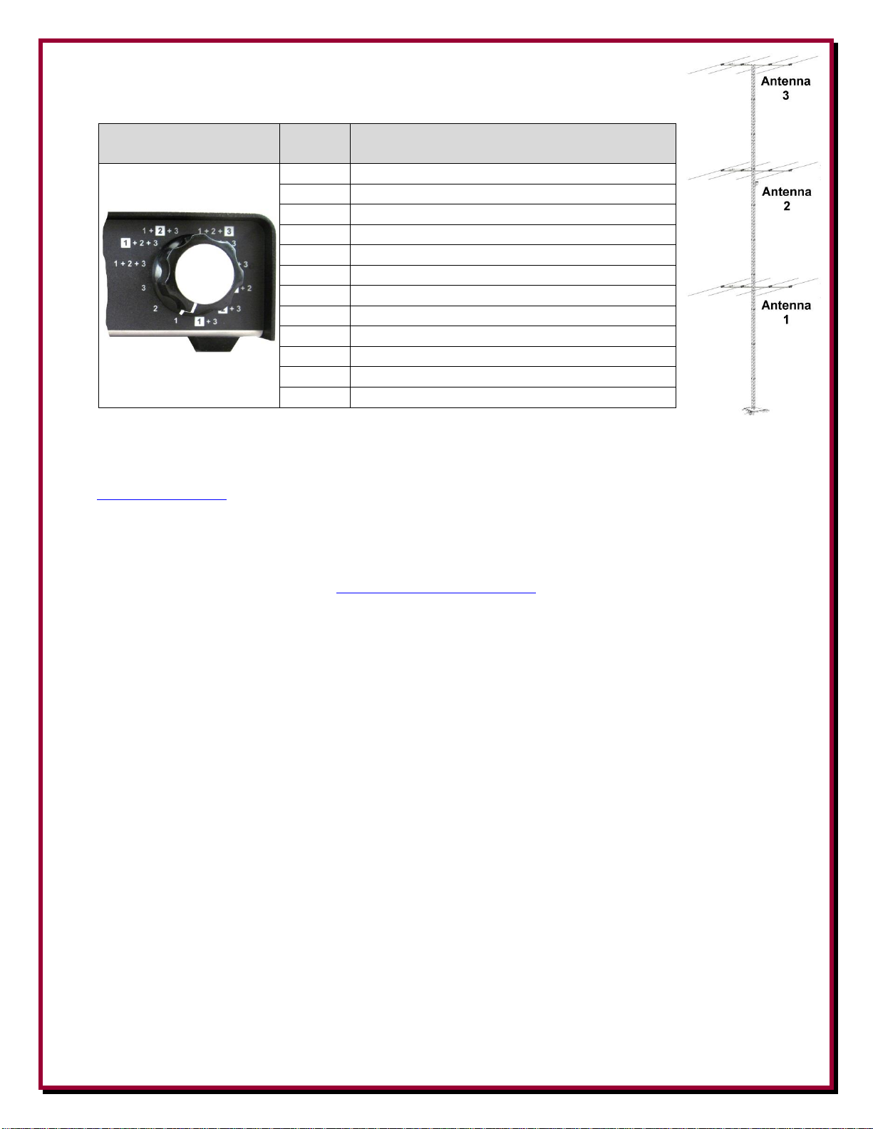
The twelve position rotary switch will have the following sequence when the
DXE-EC-PS3
Switch
Position
DXE-PS-3B Function Description
1
Antenna port 1 only
2
Antenna port 2 only
3
Antenna port 3 only
4
All three antenna ports in phase
5
All three antenna ports, 1 out of phase
6
All three antenna ports, 2 out of phase
7
All three antenna ports, 3 out of phase
8
Antenna Ports 1 and 3 in phase
9
Antenna Ports 2 and 3 in phase
10
1 & 2 antenna ports selected, 1 out of phase
11
2 & 3 antenna ports selected, 2 out of phase
12
1 & 3 antenna ports selected, 1 out of phase
control console and phasing unit are wired up G-G, 1-1, 2-2, 3-3, etc.
Manual Updates
Every effort is made to supply the latest manual revision with each product. Occasionally a manual will be updated between the time
your DX Engineering product is shipped and when you receive it. Please check the DX Engineering web site
(www.dxengineering.com) for the latest revision manual.
Technical Support
If you have questions about this product, or if you experience difficulties during the installation, contact DX Engineering at (330)
572-3200. You can also e-mail us at:
For best service, please take a few minutes to review this manual before you call.
Warranty
All products manufactured by DX Engineering are warranted to be free from defects in material and workmanship for a period of one (1) year from
date of shipment. DX Engineering’s sole obligation under these warranties shall be to issue credit, repair or replace any item or part thereof which is
proved to be other than as warranted; no allowance shall be made for any labor charges of Buyer for replacement of parts, adjustment or repairs, or
any other work, unless such charges are authorized in advance by DX Engineering. If DX Engineering’s products are claimed to be defective in
material or workmanship, DX Engineering shall, upon prompt notice thereof, issue shipping instructions for return to DX Engineering (transportationcharges prepaid by Buyer). Every such claim for breach of these warranties shall be deemed to be waived by Buyer unless made in writing. The above
warranties shall not extend to any products or parts thereof which have been subjected to any misuse or neglect, damaged by accident, rendered
defective by reason of improper installation, damaged from severe weather including floods, or abnormal environmental conditions such as prolonged
exposure to corrosives or power surges, or by the performance of repairs or alterations outside of our plant, and shall not apply to any goods or parts
thereof furnished by Buyer or acquired from others at Buyer’s specifications. In addition, DX Engineering’s warranties do not extend to other
equipment and parts manufactured by others except to the extent of the original manufacturer’s warranty to DX Engineering. The obligations under
the foregoing warranties are limited to the precise terms thereof. These warranties provide exclusive remedies, expressly in lieu of all other remedies
including claims for special or consequential damages. SELLER NEITHER MAKES NOR ASSUMES ANY OTHER WARRANTY
WHATSOEVER, WHETHER EXPRESS, STATUTORY, OR IMPLIED, INCLUDING WARRANTIES OF MERCHANTABILITY AND
FITNESS, AND NO PERSON IS AUTHORIZED TO ASSUME FOR DX ENGINEERING ANY OBLIGATION OR LIABILITY NOT STRICTLY
IN ACCORDANCE WITH THE FOREGOING.
©DX Engineering 2017
DX Engineering®, DXE®, DX Engineering, Inc.®, Hot Rodz®, Maxi-Core®, DX Engineering THUNDERBOLT®, DX Engineering Yagi Mechanical®,
EZ-BUILD®, TELREX®, Gorilla Grip® Stainless Steel Boom Clamps, Butternut®, SkyHawk™, SkyLark™, SecureMount™, OMNI-TILT™, RF-
PRO-1B®, AFHD-4® are trademarks of PDS Electronics, Inc. No license to use or reproduce any of these trademarks or other trademarks is given or
implied. All other brands and product names are the trademarks of their respective owners.
Specifications subject to change without notice.
- 4 -
 Loading...