

Page 1
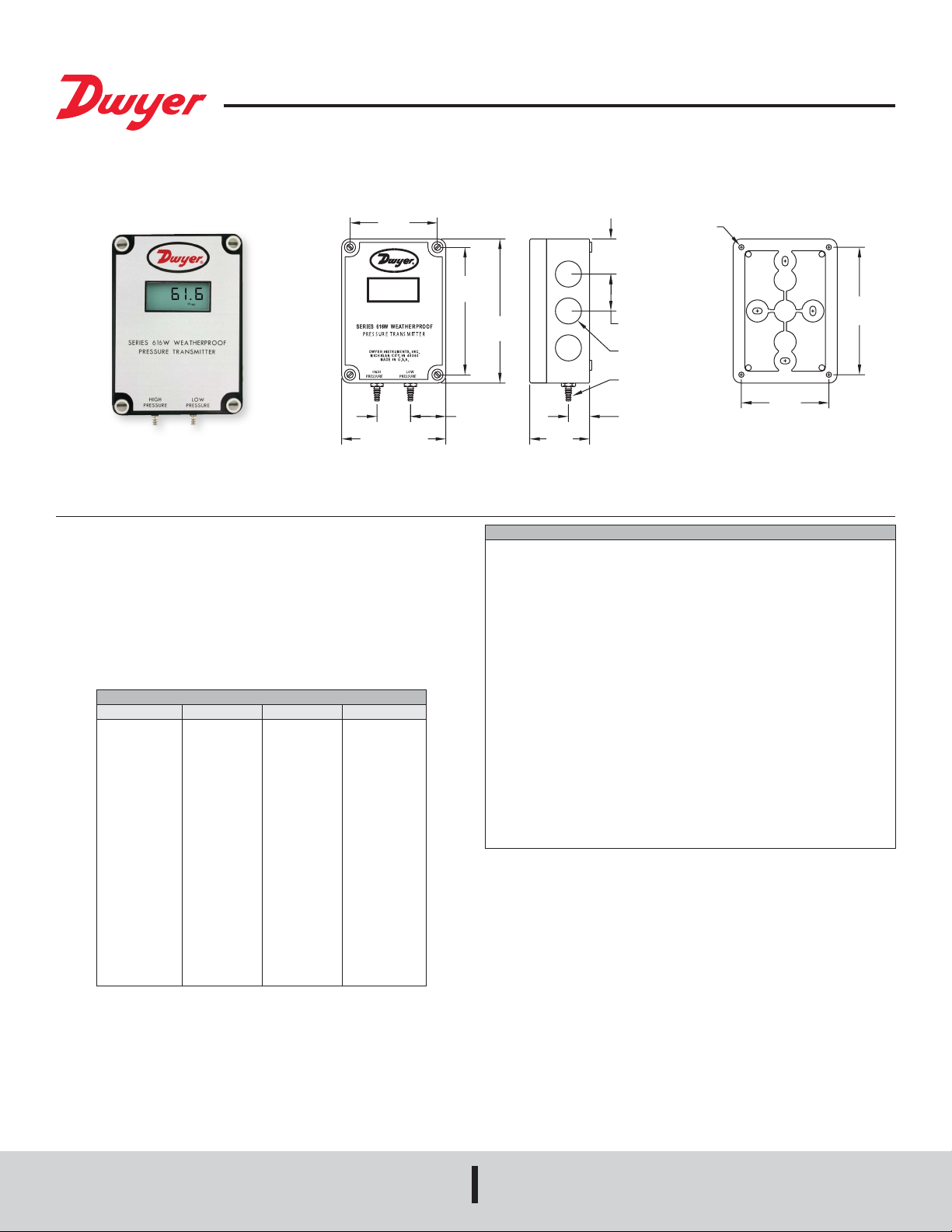
Series 616W Differential Pressure Transmitter
[53.98]
15.09]
3-1/8
®
Specications - Installation and Operating Instructions
Bulletin P-616W
[79.38]
1-3/16
[30.18]
3-3/4 [95.25]
The Series 616W Differential Pressure Transmitter senses the pressure of air and
non-combustible, compatible gases and sends a standard 4 to 20 mA or selectable
0 to 5/0 to 10 VDC output signal. All models, including those featuring an LCD, are
factory calibrated to specic ranges. Positive, negative, and differential pressures
can be measured within a full scale accuracy of ±0.25%. This weatherproof unit is
enclosed in a polycarbonate case, rated IP66/NEMA 4X. The span and zero controls
are for use when checking calibration, and are not intended for re-ranging.
Series 616W Transmitter Models & Ranges
MODEL CHART
Model Range Max. Pressure Digital Display
616W-2
616W-3
616W-4
616W-5
616W-6
616W-7
616W-2-LCD
616W-3-LCD
616W-4-LCD
616W-5-LCD
616W-6-LCD
616W-7-LCD
616W-6B-LCD
616W-10B-LCD
616W-20B-LCD
616W-2M-LCD
616W-3M-LCD
616W-4M-LCD
616W-5M-LCD
0 to 6 in w.c.
0 to 10 in w.c.
0 to 20 in w.c.
0 to 40 in w.c.
0 to 100 in w.c.
0 to 200 in w.c.
0 to 6 in w.c.
0 to 10 in w.c.
0 to 20 in w.c.
0 to 40 in w.c.
0 to 100 in w.c.
0 to 200 in w.c.
3-0-3 in w.c.
5-0-5 in w.c.
10-0-10 in w.c.
0 to 1.5 kPa
0 to 2.5 kPa
0 to 5 kPa
0 to 10 kPa
Table 1
10 psig
10 psig
20 psig
20 psig
15 psig
45 psig
10 psig
10 psig
20 psig
20 psig
15 psig
45 psig
10 psig
10 psig
10 psig
68.9 kPa
68.9 kPa
137.8 kPa
137.8 kPa
–
–
–
–
–
–
0 to 6.00
0 to 10.00
0 to 20.0
0 to 40.0
0 to 100.0
0 to 200.0
-3.00-0-3.00
-5.00-0-5.00
-10.00-0-10.00
0 to 1.50
0 to 2.50
0 to 5.00
0 to 10.0
Ø3/16 [4.76]
MOUNTING HOLES
1-1/4
[31.75]
4-1/2
[114.30]
5-1/8
[130.18]
1-1/4
[31.75]
SPECIFICATIONS
Service: Air and non-combustible, compatible gases.
Wetted Materials: Consult factory.
Accuracy: 0.25% FS @ 77°F (25°C), display accuracy ±0.5%.
Thermal Effect: ±0.02% FS/°F (±0.036% FS/°C).
Stability: ±1% FS/yr.
Temperature Limits: 14 to 185°F (-10 to 85°C).
Pressure Limits: See chart.
Power Requirements: 10 to 35 VDC (2-wire), 17 to 36 VDC, or isolated 21.6 to 33
VAC (3-wire).
Output Signal: 4 to 20 mA (2-wire), 0 to 5 VDC, or 0 to 10 VDC (3-wire)
Zero and Span Adjustments: Push buttons.
Loop Resistance: Current Output: 0 to 1250 Ω (max); Voltage Output: Load
resistance 1 kΩ (min).
Current Consumption: 40 mA max.
Electrical Connections: 3-wire removable European style terminal block for 16 to
26 AWG.
Process Connections: Barbed, dual size to t 1/8” and 3/16” (3.12 and 4.76 mm)
I.D. rubber or vinyl tubing.
Enclosure Rating: NEMA 4X (IP66).
Mounting Orientation: Any orientation.
Weight: Without LCD: 8.8 oz (249 g); With LCD: 9.6 oz (272 g).
Agency Approvals: CE.
2-1/8
TYP 4 PLACES
1-5/16 [33.32] TYP
7/16 OR 5/8
[11.13 OR 15.88]
TYP
1/8 AND 3/16
[3.18 AND 4.76]
I.D. TUBING
3/4 [19.05] TYP
3-1/8
[79.38]
4-17/32
[1
DWYER INSTRUMENTS, INC.
P.O. BOX 373 • MICHIGAN CITY, INDIANA 46360, U.S.A.
Phone: 219/879-8000
Fax: 219/872-9057
www.dwyer-inst.com
e-mail: info@dwyermail.com
Page 2
INSTALLATION
1. Location: Select a clean, dry mounting location free from excess vibration where
the temperature will remain between 14 to 185°F (-10 to 85°C). Distance from the
receiver is limited only by total loop resistance. See Electrical Connections below.
The tubing supplying pressure to the instrument can be practically any length
required, but long lengths will increase response time slightly.
2. Position: A vertical position, with the pressure connection pointing down, is
recommended. That is the position in which all standard models are spanned and
zeroed at the factory. They can be used at other angles, but nal spanning and
zeroing must be done while the transmitter is in that alternate position.
3. Pressure Connections: Two integral barbed tubing connections are provided.
They are dual-sized to t both 1/8” and 3/16” (3.12 and 4.76 mm) I.D. tubing. Be
sure the pressure rating of the tubing exceeds that of the operating range. On
ranges over 20 psi, we recommend use of a suitable hose clamp to assure the
integrity of the connection.
ELECTRICAL CONNECTIONS
2-Wire 4 to 20 mA Current Operation
CAUTION
Do not exceed specied supply voltage ratings. Permanent
damage not covered by warranty will result. Simultaneous
outputs are not designed for AC voltage operation.
The connections to the transmitter are made through terminals 2 and 3 on the terminal
block as shown in Figure 2. The terminal block is removable and each of the terminals
are labeled underneath the terminal block on the circuit board. Polarity is indicated by
terminals 2 (+IOUT) and 3 (–IOUT). The AC/DC selection jumper should be set for
DC operation.
CAUTION
Do not exceed specied supply voltage ratings. Permanent
damage not covered by warranty will result. This unit is not
designed for 120 or 240 VAC line operation.
Electrical connections are made to the terminal block located on the inside of the
transmitter. Determine which of the following circuit drawings best applies to your
application and wire accordingly.
Electrical Connection
The Series 616W simultaneously transmits a 2-wire 4 to 20 mA current output and
a 3-wire 0 to 5 V / 0 to 10 V voltage output via a removable European-style three
conductor terminal block. The transmitter can be wired in one of the following three
ways to utilize the current and/or voltage output.
Power Supply
Refer to Table 2 for the required supply rating.
MODEL CHART
Output Type Power Supply Rating
2-wire current
3-wire current
Simultaneous current and voltage
10 to 35 VDC (40 mA min)
17 to 36 VDC or 21.6 to 33 VAC (40 mA min)
17 to 35 VDC (40 mA min)
Table 2
Choose a power supply with a voltage and current rating sufcient to meet the power
specications under all operating conditions. If the supply is unregulated, make sure
that the output voltage remains within the required voltage range under all power line
conditions. Ripple on the supply should not exceed 100 mV.
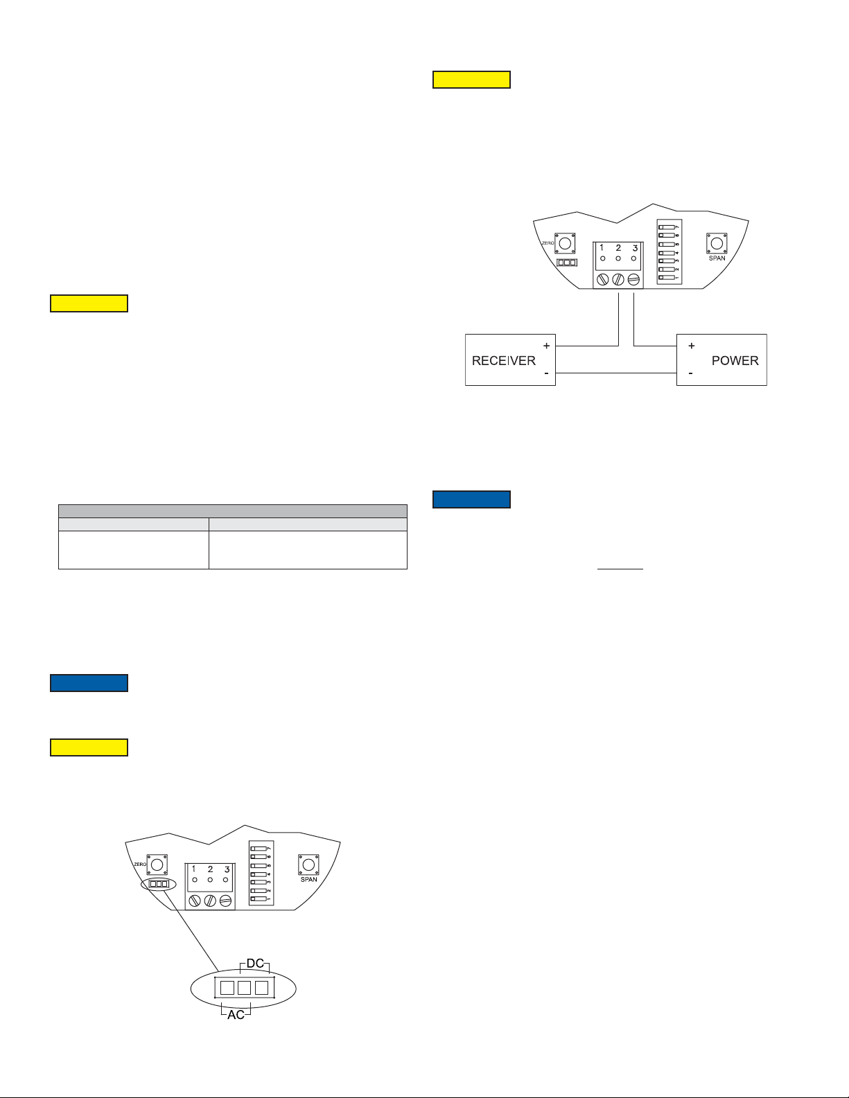
AC/DC Jumper Selection
NOTICE
The jumper is factory set to AC. If DC power is applied while
the jumper is set to AC, no damage will occur. However, the
accuracy of the unit may be temporarily affected.
Figure 2: Current Output Wiring
The range of appropriate receiver load resistances (RL) for power supply voltage
available is given by the formula listed below. Shielded 2-wire cable is recommended
for control loop wiring. Ground the shield at the power supply end.
NOTICE
The receiver may be connected to either the negative or positive
side of the loop, whichever is most convenient. Should the
polarity of the transmitter or receiver be inadvertently reversed, the loop will not
function properly, but no damage will be done to the transmitter.
PS - 10.0
V
L =
R
20 mA DC
The maximum length of connecting wire between the transmitter and the receiver is
a function of wire size and receiver resistance. That portion of the total current loop
resistance represented by the resistance of the connecting wires themselves should
not exceed 10% of the receiver resistance. For extremely long runs (over 1,000
ft/305 m), it is desirable to select receivers with lower resistances in order to keep the
size and cost of the connecting leads as low as possible. In installations where the
connecting run is no more than 100 ft (30.5 m), connecting lead wire as small as No.
22 ga. can be used.
CAUTION
Powering the unit with AC power while the jumper is set to DC
may permanently damage the transmitter.
Refer to Figure 1 for the location of the AC/DC jumper. Place the shorting jumper
across either the two pins marked AC or the two pins marked DC.
Figure 1: AC/DC Jumper
Page 3

3-Wire 0 to 10 V and 0 to 5 V Voltage Operation
CAUTION
Do not exceed specied supply voltage ratings. Permanent
damage not covered by warranty will result.
The connections to the transmitter are made to Terminals 1, 2, and 3 on the terminal
block as shown in Figure 3. The terminal block is removable and each of the terminals
are labeled underneath the terminal block on the circuit board. Polarity is indicated
by 1, 2, and 3. When connecting using a DC power source, make sure the AC/DC
selection jumper is set for DC. If the polarity of the transmitter is inadvertently reversed,
the unit will not function properly, but no damage will be done to the transmitter. When
connecting to an AC power source, make sure the AC/DC selection jumper is set for
AC. Either lead of the supply power may be connected to terminals 1 and 2 without
affecting the operation of the transmitter or causing damage to the transmitter.
Figure 3: Voltage Output Wiring
The minimum receiver load is 1 kΩ. The resistance due to the wire should be low
compared to the receiver load resistance. While the voltage at the terminal block
remains unchanged with a 10 mA current ow, resistive losses in the wiring do cause
errors in the voltage delivered to the receiver. For a 1% accuracy gauge, the resistance
of the wires should be less than 0.1% of the value of the receiver load resistance. This
will keep the error caused by the current ow below 0.1%.
Simultaneous Current and Voltage Operation
CAUTION
Do not exceed specied supply voltage ratings. Permanent
damage not covered by warranty will result. Simultaneous
outputs are not designed for AC voltage operation.
The connections to the transmitter are made to Terminals 1, 2, and 3 on the terminal
block as shown in Figure 4. The terminal block is removable and each of the terminals
are labeled underneath the terminal block on the circuit board. Polarity is indicated by
terminals 1, 2, and 3. The AC/DC selection jumper should be set for DC operation.
The voltage output and the power supply must have separate wire leads that are only
joined at terminal 2 of the transmitter. Additional error may occur for the voltage output
if a single wire is used or if the wires are joined at the power supply or receiver.
For the current output, the maximum allowable loop resistance (wiring + receiver
resistance) is dependent on the power supply. The maximum loop voltage drop must
not reduce the transmitter voltage below 17 V. The maximum loop resistance can be
calculated using the following equation:
R
MAX =
PS - 17.0
V
20 mA DC
(where VPS is the power supply voltage)
The equation uses 17.0 instead of 10.0 used in the current only equation. This
represents the minimum voltage supply which is higher on the simultaneous output
conguration due to the requirements of the voltage outputs.
Shielded 4-wire cable is recommended for control loop wiring. Ground the shield
at the power supply end only. Should the polarity of the transmitter or receiver be
inadvertently reversed, the unit will not function properly, but no damage will be done
to the transmitter.
For voltage outputs, the minimum receiver load is 1 kΩ. The resistance due to the
wire should be low compared to the receiver load resistance. While the voltage at
the terminal block remains unchanged with a 10 mA current ow, resistive losses in
the wiring do cause errors in the voltage delivered to the receiver. For a 1% accuracy
gauge, the resistance of the wires should be less than 0.1% of the value of the receiver
load resistance. This will keep the error caused by the current ow below 0.1%.
CALIBRATION
NOTICE
There is a 5 second delay from the time the zero or span
calibration button is released until the time that the change in
the calibration takes place. This delay is used to prevent stress related offsets on
the lower range.
Zero Calibration
The zero calibration can be set by applying zero pressure to both the pressure ports
and pressing the zero button for 3 seconds. If either the remote or local LCD is present,
the display will read ZEro and then sequence back to the home display.
Span Calibration
The span calibration can be adjusted only after setting the zero adjustment. It must be
completed within 5 minutes of the last zero calibration. The span calibration button will
be ignored until the zero calibration is completed. Apply pressure to the ports of the
transmitter that are associated with the maximum output of the transmitter (20 mA, 5
V, or 10 V, depending on the output being used). Press and hold the span button for 3
seconds. If either the remote or local LCD are present, the display will read SPAn and
then sequence back to the home display. If the span calibration is attempted before
adjusting the zero calibration, the FAiL error message will ash on the display. On
bi-directional models, separate spans can be performed on the positive and negative
sides of the range.
ZERO DEADBAND
Figure 4: Simultaneous Current and Voltage Output Wiring
Figure 5
MAINTENANCE/REPAIR
Upon nal installation of the Series 616W Differential Pressure Transmitter, no routine
maintenance is required. The Series 616W is not eld serviceable and is not possible
to repair the unit. Field repair should not be attempted and may void warranty.
This symbol indicates waste electrical products should not be disposed
of with household waste. Please recycle where facilities exist. Check with
your Local Authority or retailer for recycling advice.
WARRANTY/RETURN
Refer to “Terms and Conditions of Sale” in our catalog and on our website. Contact
customer service to receive a Return Goods Authorization number before shipping the
product back for repair. Be sure to include a brief description of the problem plus any
additional application notes.
Page 4

NOTES
__________________________________________________________________________________________________________________________________________
__________________________________________________________________________________________________________________________________________
__________________________________________________________________________________________________________________________________________
__________________________________________________________________________________________________________________________________________
__________________________________________________________________________________________________________________________________________
__________________________________________________________________________________________________________________________________________
__________________________________________________________________________________________________________________________________________
__________________________________________________________________________________________________________________________________________
__________________________________________________________________________________________________________________________________________
__________________________________________________________________________________________________________________________________________
__________________________________________________________________________________________________________________________________________
__________________________________________________________________________________________________________________________________________
__________________________________________________________________________________________________________________________________________
__________________________________________________________________________________________________________________________________________
__________________________________________________________________________________________________________________________________________
__________________________________________________________________________________________________________________________________________
__________________________________________________________________________________________________________________________________________
__________________________________________________________________________________________________________________________________________
__________________________________________________________________________________________________________________________________________
__________________________________________________________________________________________________________________________________________
__________________________________________________________________________________________________________________________________________
__________________________________________________________________________________________________________________________________________
__________________________________________________________________________________________________________________________________________
__________________________________________________________________________________________________________________________________________
__________________________________________________________________________________________________________________________________________
__________________________________________________________________________________________________________________________________________
©Copyright 2019 Dwyer Instruments, Inc. Printed in U.S.A. 1/19 FR# 444343-10 Rev. 5
DWYER INSTRUMENTS, INC.
P.O. BOX 373 • MICHIGAN CITY, INDIANA 46360, U.S.A.
Phone: 219/879-8000
Fax: 219/872-9057
www.dwyer-inst.com
e-mail: info@dwyermail.com
 Loading...