


616KD
Series 616KD One-Touch
®
Differential Pressure Transmitter
Specications - Installation and Operating Instructions
Bulletin P-616KDX
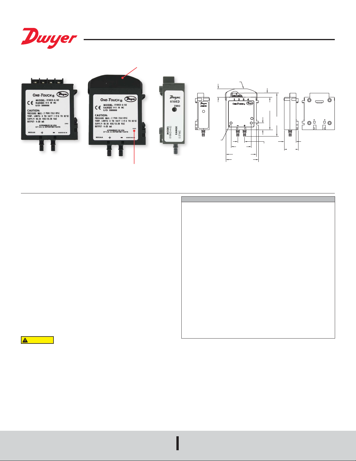
The Series 616KD One-Touch
®
Differential Pressure Transmitter senses the
pressure of air and compatible gases and sends a standard 4 to 20 mA or optional
voltage output signal. A wide range of models are available factory calibrated to
specic ranges. A single push button properly adjusts both zero and span. New
enclosure enables the 616KD-A/B to be mounted on a 35 mm DIN rail either via its
side or back DIN rail clips.
INSTALLATION
1. Location
Select a clean, dry mounting location free from excess vibration where the
temperature will remain between 20 and 122°F (-6.7 and 50°C). The tubing supplying
pressure to the instrument can be practically any length required, but long lengths
will increase response time slightly.
2. Position
A vertical position, with pressure connections pointing down, is recommended.
That is the position in which all standard models are calibrated at the factory. Consult
factory for other position orientations.
3. Pressure Connections
Two integral barbed tubing connections are provided. They are dual-sized to t both
1/8 and 3/16˝ (3.12 and 4.76 mm) I.D. tubing. Be sure the pressure rating of the
tubing exceeds that of the operating ranges.
4. Electrical Connections:
Electrical connections are made to the terminal block located on the top of the
transmitter. Terminals are marked 1, 2, 3 and 4 as shown below. Determine which
of the following circuit drawings applies to your application and wire accordingly.
Shielded cable is recommended. Ground the shield at the power supply end only.
SPECIFICATIONS
Service: Air and non-combustible, compatible gases.
Wetted Materials: Consult factory.
Accuracy: 616KD-A: ±0.25% FS; 616KD-B: ±1% FS; 616KD-C: ±2% FS.
Stability: ±1% FS/year.
Temperature Limits: 0 to 140°F (-17.8 to 60°C).
Compensated Temperature Range: 20 to 122°F (-6.67 to 50°C).
Pressure Limits: 2 psig (ranges 5 in w.c. or lower); 5 psig (ranges 10 to 40 in w.c.).
Thermal Effect: 616KD-A: ±0.02% FS/°F; 616KD-B: ±0.04% FS/°F; 616KD-C:
±0.06 FS/°F, includes zero and span.
Power Requirements: 4 to 20 mA output: 10 to 35 VDC (2 wire) or 12 to 26 VAC (4
wire); 5V output: 10 to 35 VDC (3 wire) or 12 to 26 VAC (4 wire); 10V output: 13 to
35 VDC (3 wire) or 12 to 26 VAC (4 wire).
Output Signal: 4 to 20 mA or option with eld selectable 0 to 10, 0 to 5, 2 to 10, 1
to 5 volts.
Zero and Span Adjustments: Push button.
Loop Resistance: 4 to 20 mA output (DC): 0 to 1250 Ω max. Rmax = 50(VpsDC
-10) Ω; 4 to 20 mA output (AC): 0 to 1200 Ω max. Rmax = 50(1.4 VpsAC -12) Ω;
Voltage output: 5K Ω minimum.
Current Consumption: 24 mA max.
Electrical Connections: Screw-type terminal block.
Process Connections: Barbed, dual size to t 1/8˝ & 3/16˝ (3 mm & 5 mm) ID
rubber or vinyl tubing.
Enclosure Rating: NEMA1 (IP20).
Mounting Orientation: Vertical with pressure connections pointing down.
Weight: 1.8 oz (51 g).
Agency Approvals: CE.
Do not exceed specied supply voltage ratings. Permanent
damage not covered by warranty will result. This unit is not
designed for 120 or 240 volts AC line operation.
CAUTION
7/8
[22.23]
1/2
[12.70]
2-13/32
[61.12]
3-21/64
[84.53]
5/16
[7.94]
Ø5/32 [3.97]
MOUNTING HOLE
2 PLACES
1/2
[12.70]
1-1/2
[38.10]
2-1/4 [57.15]
5/8
[15.88]
OPTIONAL
TERMINAL
COVER
1-1/32
[26.19]
2-13/32 [61.12]
Optional protective cap
Digital push button
sets both zero & span
®
DWYER INSTRUMENTS, INC.
P.O. BOX 373 • MICHIGAN CITY, INDIANA 46360, U.S.A.
Phone: 219/879-8000
Fax: 219/872-9057
www.dwyer-inst.com
e-mail: info@dwyermail.com
 Loading...