

Page 1
ViewRite
Magnetic Liquid Level Indicator
Instruction Bulletin No. 204129
Thank you for purchasing the Dwyer ViewRite Magnetic Level Indicator . Please read this document prior to installing your
ViewRite and store it where it may be readily referred to for familiarization and maintenance purposes. If you require any
additional information, you are welcome to call Dwyer at the number shown below.
1-219-879-8000
Record the Part Number of your ViewRite here to use when ordering spare or replacement parts:
Part Number:____________________
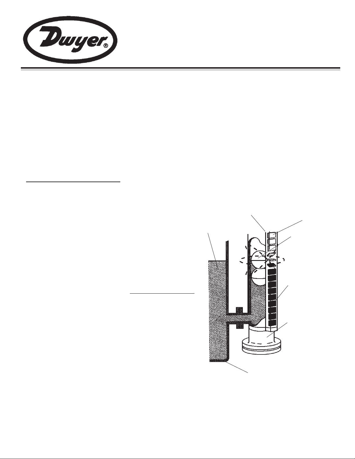
ViewRite Operating Principle
The liquid level of a tank is made visible, even at great distances,
through the use of a shock and vibration-proof magnetic level indicator
that employs “flags” arranged within a specially constructed external
housing: the flag assembly . The two sides of each pivoting flag are
marked with contrasting colors. A permanent magnet is encapsulated
inside each flag and forms a secure magnetic interlock with the
adjacent flags. As the liquid level rises, a float equipped with a
permanent magnet causes each of the flags to begin rotating in turn.
This action exposes the contrasting (fluid level indicating) color on
the other side of the flag. As the float and liquid level rise, each flag
below the level of the float completes a 180 degree rotation, while
remaining magnetically interlocked with the other lower flags.
Together, the rotated flags display a band or column of color, the
height of which corresponds with the liquid level within the tank. An
exclusive feature of the ViewRite is the patented magnetic guide
that is integrated into the flag assembly. This magnetic attraction
ensures that the float is always aligned for optimum performance
and exactness, regardless of any shock, vibration, or rapid change
to the level of fluid in the tank.
Flag Channel
Liquid
Magnetic Flags
(Plain Side Out)
Magnetic
Float
Magnetic Flags
(Colored
Side Out)
Weldment
Standard and Mini-ViewRites are supplied with the floats packed
either separately , or securely strapped to the unit. The float supplied
with each unit has been designed to the specific gravity of the fluid
being monitored, so that the permanent bar magnet will always seek
and indicate the fluid surface. Because of the attraction of the
permanent bar magnet in the float and the patented magnetic guide,
the ViewRite flag assembly can be rotated to a position which will
allow for optimum viewing.
Tank
(See the Maintenance Section on page 4 for instructions on how to rotate your
ViewRite flag assembly.)
- 1 -
Page 2

Important!
Read the following instructions completely - BEFORE installing the ViewRite.
Installation Precautions and Preparation
Failure to observe these precautions could affect the operation of your unit.
1. When locating the tank ports for the ViewRite, make sure that no strong magnetic fields or magnetic materials
(such as railings, protective cages, I-beams, etc.) will be any closer than 6 inches (153 mm) from the ViewRite.
2. Make necessary efforts to ensure that all tank-side modifications and equipment; i.e., the mating flanges, NPT
ports or shut-off valves (if used) will align properly with the connections. Improper alignment could
cause distortion and may damage welds and compromise the integrity of the ViewRite and/or the tank.
3. After any necessary tank modifications are completed, the tank should be cleaned to remove contaminants. This
will ensure that the installation is free of foreign particles; especially those which could be magnetic and which
could impair the performance of the ViewRite.
4. Do not begin the installation of the ViewRite until all necessary tools and materials are obtained. (Such as
mating flange gaskets, bolting hardware, etc. )
5. Gasket material typically supplied with the standard ViewRite unit is either Viton or nitrile rubber, Garlock 3000
style. Higher pressure units are typically supplied with FlexitallicTM gaskets.
6. All supplied flag assembly clamps are intended to be installed with a torque on the clamp screw not to exceed
5 lb.-inches.
Installation
Caution
Handle the ViewRite with care to avoid damaging the threaded areas, flange surfaces, etc.
For Standard ViewRites (Alloy and Mini)
1. Remove the protective packing materials from your ViewRite.
2. Position the unit horizont ally on a level surface.
3. Unpack the float assembly or, with the aid of a wire-cutter or similar device, remove the strapping that secures
the float to the exterior of the ViewRite Unit.
- 2 -
Page 3
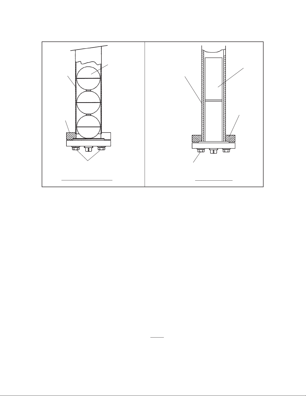
Warning
D0 NOT : 1) Hold the V iewRite in a vertical position or 2) Drop the float assembly into the unit. Avoid this or
any action which could damage or dent the float. Such damage could cause the float to crush under normal
working pressures.
TOP
Weldment
Float
TOP
Weldment
Float
Flange
Flange
Remove Bolts
Standard ViewRite
Remove Bolts
Mini ViewRite
4. Remove the end cap or flange attaching bolts, as indicated in the appropriate drawing. Then remove
the end cap or flange.
5. With the unit still in a horizontal position, insert the float assembly into the weldment, with the “TOP” indication
on the float assembly moving in the same direction as the “UP” arrows that are located on each side of the
externally mounted flag assembly.
6. With the gasket or O-ring properly positioned, reassemble the end cap or flange to the weldment. Tighten the
end cap or flange bolts securely, using the proper recommended torque value as supplied in Figure A, page 4.
7. Slowly raise the top end of the ViewRite, while the bottom end remains on the level surface, permitting the float
to slowly slide to the bottom, avoiding any sudden impact damage to the float assembly.
8. Move the ViewRite to the tank and position the unit with the end marked “TOP” pointing upwards. Install any
necessary mounting gaskets or seals1, and align the mating port flanges, NPT’s or connections of the tank with
those of the ViewRite. DO NOT A TTEMPT T O FORCE ALIGNMENT. To do so may damage the welds or
compromise the integrity of the ViewRite. While following standard practices and procedures, tighten the flange
bolts, NPT’s or connections. Recommended torque values are supplied in Figure A, page 4.
9. Before Filling the T ank . . . . Be sure that the inst allation is free of foreign particles, especially any that are
magnetic. Check that all connections are secure. A hydrostatic pressure test of the complete assembly
is recommended.
NOTE
Dwyers recommends that you include at least one support bracket in your installation for ViewRite units greater than
10 feet (120 inches, 3048 mm) in length. Depending on the specific installation, a load-bearing support at the base
of the ViewRite may be beneficial.
______________________________________
1
Gaskets or seals for the port flanges are not supplied with the ViewRite.
- 3 -
Page 4

Figure A
(Recommended Torque Values are for Lubricated Threads, Only)
Indicator Type
Fastener
Description
Nominal
Size
Torque Value
70 - 80 Lb.-Inches NTE
(Not to Exceed) 120 Lb.-Inches
30 Lb-Feet
60 Lb-Feet
100 Lb-Feet
150 Lb-Feet
250 Lb-Feet
350 Lb-Feet
70 - 80 Lb-Inches
Standard Alloy,
Top-Mount Alloy
Mini
Bolt, Nut
Bolt, Nut
3/8 Inch
1/2 Inch
5/8 Inch
3/4 Inch
7/8 Inch
1 Inch
1-1/8 Inch
5/16 Inch
Flag Installation
General Notes
Under normal circumstances, it should not be necessary to reposition the flag assembly on your ViewRite. However , if
you find it desirable or necessary to reposition the flag assembly , we strongly recommend that you first mark the distance from the top of the weldment to the top of the flag assembly. Before securing the flag assembly in a new radial
position, ensure that the distance from the top of the flag assembly to the top of the weldment is the same as the previously noted dimension. Making a temporary or permanent mark on the weldment can ease the process.
Maintenance
The only maintenance typically required is to ensure that the internal walls of the weldment and the float are free of
foreign matter. This may be accomplished by removing the float assembly from the unit and wiping both the float and
the inside wall of the float chamber or weldment. Any maintenance interval is to be est ablished by the user of the
ViewRite and would depend upon the characteristics of the application. Maintenance could coincide with tank cleaning
or flushing.
Float Installation
Mini ViewRite Float:
T o accomplish the removal and subsequent reinst allation of the float assembly , follow the appropriate instructions provided on page 5 for the ViewRite type and mounting configuration you have selected.
To set magnet position hold the float vertical. A paper clip will attach to the magnet to show its position. Adjust the
magnet position by gently tapping the end of the float.
Basic Float Part No. 807100
(Liquid Specific Gravity Range: 0.8 to 1.2)
Float
Part Number
85206
83453
85208
85209
84158
Dimension
“X”
Liquid
Specific
Gravity
0.8
0.9
1
1.2
0.85
“X”
Dimension
5”
4.5”
4”
3.312”
4.75”
TOP
807100
(Liquid Specific Gravity Range: 1.5 to 3.8)
- 4 -
Basic Float Part No. 807200
Float
Part Number
88111
801708
“X”
Dimension
Liquid
Specific
Gravity
1.9
1.5
“X”
Dimension
2”
2.6875”
TOP
807200
Caution
Make sure that the tank is depressurized
and that liquid has been emptied prior to
removal of the float assembly.
Page 5

ViewRite with Side Connections (Alloy and Mini)
The float assembly can be removed without disturbing the mounting of the ViewRite unit to the tank.
1. Carefully remove the end cap (access to the float assembly) which may be retained by bolts or NPT threads.
The float assembly should be resting on the end cap as it is being lowered.
Support the float assembly while setting the end cap aside.
Note: For units supplied with top float access, the float assembly must be
extracted from the top of the weldment by engaging the hooking ring
provided on the top of the float.
2. Withdraw the float assembly from the unit, exercising caution not to damage the float. Note the “TOP”
indication marking on the float assembly.
3. Wipe down the weldment and the float assembly with a clean, lint-free cloth.
4. Carefully reinsert the float assembly into the weldment, ensuring that the “TOP” indication marking on the
float assembly is positioned in the same manner as when it was removed.
5. Remove the old gasket or O-ring from the end cap assembly and replace it with a new gasket or O-ring.
6. With the new gasket or O-ring properly positioned, reassemble the end cap assembly to the weldment.
Tighten the end cap or secure flange fasteners, using the proper recommended torque value, as supplied
in Figure A -page 4.
ViewRite with Top and Bottom Connections (Alloy and Mini)
The ViewRite unit should be adequately supported when removing it from the tank.
1. Disconnect the top and bottom flange/socket or NPT connections.
2. Remove any other fasteners that retain the unit and/or support bracket(s) to the tank.
3. Remove the ViewRite unit from the tank, while avoiding any motion that will cause damage to the float assembly.
4. With the ViewRite placed in a horizontal position on a level surface, remove the end cap or flange and withdraw
the float assembly from the unit; noting the relative position of the portion of the float assembly marked “TOP”.
5. Wipe down the weldment and the float assembly with a clean, lint-free cloth.
6. Carefully reinsert the float assembly into the bottom of the float chamber or weldment, ensuring that the “TOP”
indication marking on the float assembly is positioned the same as when it was removed.
7. Remove the old gasket or O-ring from the end cap assembly and replace it with a new gasket or O-ring.
8. With the new gasket or O-ring properly positioned, reassemble the end cap assembly to the bottom of the
weldment. Tighten the end cap or flange bolts securely, using the proper recommended torque value, as
supplied in Figure A, page 4.
9. Complete installation of the unit by following the Installation Instructions for Standard ViewRites (Page 3,
Steps 7, 8 and 9).
- 5 -
Page 6

Indicating Scale
This Indicating Scale provides a numerical readout of
the liquid level in the tank, in addition to the visual level
displayed by the flag assembly. The indicating scale
is mounted alongside the flag assembly with special
clamps. The scale is normally graduated in inches
and feet, but may be graduated in other dimensional
or volumetric units. Scales that have an overall length
of more than 24 inches will be provided in two or more
sectional lengths.
Installation
Scales ordered with the ViewRite Magnetic Level Indicator are factory-installed. If ordered
separately, please follow the instructions below.
Mounting
The scale is simply installed on your ViewRite Magnetic Level Indicator using the bracketed
clamps supplied.
1. Att ach the scale onto the ViewRite Magnetic Level Indicator, wrapping the clamps around the flag
assembly and the weldment.
2. Tighten the clamps securely, with a torque not to exceed 5 lb.-inches.
- 6 -
Page 7

Troubleshooting
Condition Possible Cause
No Float
Float sticking, due to contamina-
No change in Media
Level Indication
Incorrect Fluid Level
Indication
tion in the fluid level
Float attracted, due to external
ferrous materials within close
proximity.
The float is damaged
Port is blocked
Float attracted, due to contami-
nation in the media
Float sticking, due to external
ferrous materials within close
proximity
Solution
Install float
Clean the float and weldment
Remove the ferrous materials
from close proximity
Replace the float
Remove blockage
Clean the float and weldment
Remove the ferrous materials
from close proximity
The float is damaged
The float is upside down
Flag assembly is upside-down.
Incorrect Color
Indicating Fluid Level
Note: Increased viscosity increases the response time of the ViewRite indicator
Warnings/Cautions
1. The ViewRite Magnetic Level Indicator must be maintained and installed in strict accordance with
this Instruction Bulletin. Failure to observe this warning could result in serious injuries or damages.
2. The liquids to be monitored must be compatible with the materials of construction. Specifications
of these materials will be provided upon request.
(The wrong color is indicating the
liquid level)
Replace the float
Invert the float
Rotate the flag assembly 180
degrees (with the end marked
“TOP” uppermost)
- 7 -
Page 8

MAINTENANCE/REPAIR
Regular maintenance of the total system is recommended to assure sustained optimum performance. These devices are
not field repairable and should be returned to the factory if recalibration or other service is required. After first obtaining a
Returned Goods Authorization (RGA) number , send the unit freight prep aid to the following. Please include a clear
description of the problem plus any application information available.
Dwyer Instruments, Inc.
Attn: Repair Department
102 Highway 212
Michigan City , IN 46360
Important Points!
Product must be maintained and installed in strict accordance
with the National Electrical Code and Dwyer product catalog
and instruction bulletin. Failure to observe this warning could
result in serious injuries or damages.
For hazardous area applications involving such things as (but
not limited to) ignitable mixtures, combustible dust and
flammable materials, use an appropriate explosion-proof
enclosure or intrinsically safe interface device.
The pressure and temperature limitations shown on the
individual catalog pages and drawings for the specified flow
switches must not be exceeded. These pressures and
temperatures take into consideration possible system surge
pressures/temperatures and their frequencies.
Selection of materials for compatibility with the media is critical
to the life and operation of Dwyer products. Take care in the
proper selection of materials of construction, particularly wetted
materials.
DWYER INSTRUMENTS,INC.
P.O.BOX 373 MICHIGAN CITY , INDIANA 46361, U.S.A.
Life expectancy of switch contacts varies with applications.
Contact Dwyer if life cycle testing is required.
Ambient temperature changes do affect switch set points,
since the specific gravity of a liquid can vary with temperature.
Dwyer Products have been designed to resist shock and
vibration; however, shock and vibration should be minimized.
Filter liquid media containing particulate and/or debris to
ensure the proper operation of our products.
Electrical entries and mounting points in an enclosed tank
may require liquid/vapor sealing.
Dwyer Products must not be field-repaired.
Physical damage sustained by the product may render it
unserviceable.
Phone: 219/879-8000 www.dwyer-inst.com
Fax: 219/872-9057 e-mail: info@dwyer-inst.com
Lit-By Fax: 888/891-4963
- 8 -
 Loading...