

Page 1
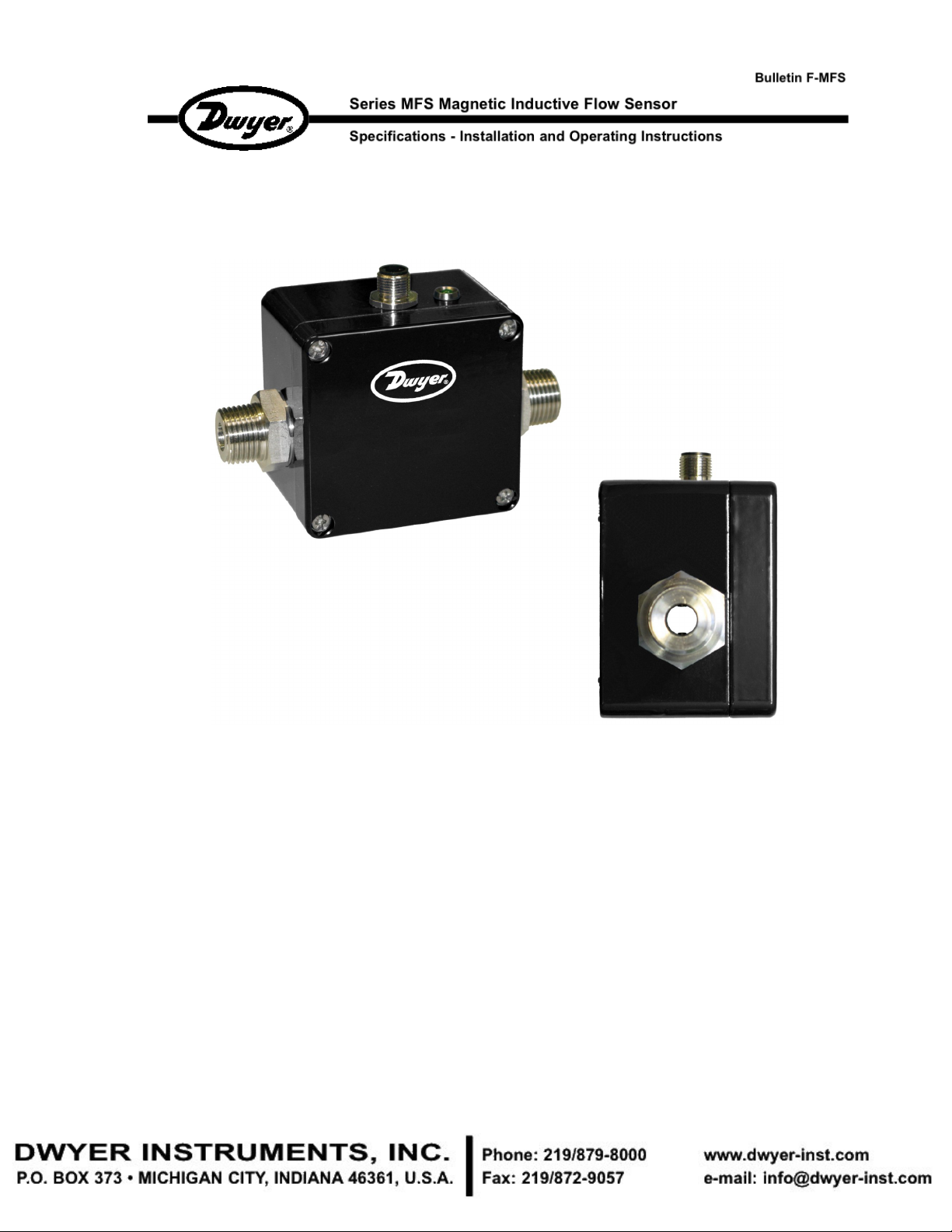
Table of contents page
1. Device description and intended use ...............................................................................................2
2. Safety instructions ............................................................................................................................2
2.1 Qualified personnel ...................................................................................................................3
2.2 Special safety instructions ........................................................................................................3
3. Unpacking and inspecting the delivery.............................................................................................4
4. Material specifications of components .............................................................................................4
5. Suitable liquids (medium) .................................................................................................................4
6. Installation of the flow sensor ...........................................................................................................4
6.1 Mechanical installation..............................................................................................................4
6.2 Electrical connection .................................................................................................................6
7. Maintenance and repairs ..................................................................................................................7
8. Decommissioning and disposal........................................................................................................7
9. Technical data ..................................................................................................................................7
10. Dimensions, pressure drop...............................................................................................................8
Page 2
Device description and intended use Series MFS
1 Device description and intended use
Series MFS sensors are used for continuously measuring flow rates or dosing electrically conductive liquids. The
operational safety of the supplied equipment is only guaranteed if it is operated according to its intended use
(measuring and dosing of liquids). The specified limit values (see the chapter “Technical Data”) should never be
exceeded.
It is the user's responsibility to select the appropriate technology which is suitable for the specific application, to
install it correctly, to carry out tests, and to maintain all the components.
The magnetic inductive flow sensor features no moving parts and is, therefore, almost wear free and suitable for
a wide range of measuring applications. A flow-proportional frequency signal is provided as the output signal.
Product label
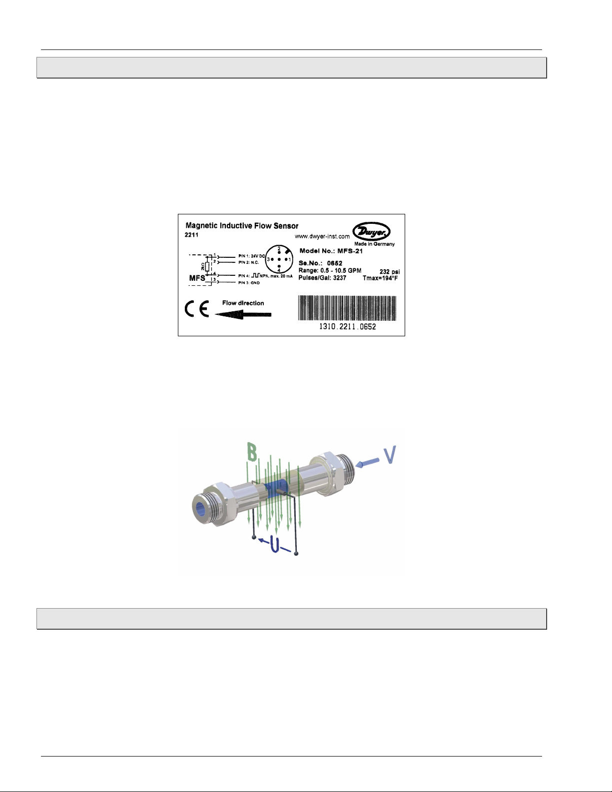
Functional principle
The magnetic inductive flow sensor functions according to the induction principle:
The measuring pipe is located in a magnetic field (B). If an electrically conductive medium (V) flows through the
measuring pipe and, therefore, at right angles to the magnetic field, a voltage (U) which is proportional to the
mean flow velocity will be induced in the medium and subsequently picked up by the two electrodes.
Fig. 1: Functional principle
2 Safety instructions
Always read the operating instructions carefully prior to installing the new product. Always adhere to the
instructions contained herein, especially the safety instructions, otherwise there is a potential risk of personal
injury and damage to instruments and systems.
Even though assistance is provided through personal consultation or this manual, it is the responsibility of the
customers to determine the suitability of the product for the specific application.
The magnetic inductive flow sensors are state-of-the-art devices, concerning the accuracy, functioning and safe
operation of the device.
However, professional and safety conscious conduct of the operator is required to ensure safe operation.
Technical changes reserved 2 08/2011
Page 3

Safety instructions Series MFS
2.1 Qualified personnel
The personnel entrusted with installing, operating and maintaining the MFS have to be suitably qualified;
the required knowledge can be gained via training courses or appropriate on-the-job instruction. The
personnel must be familiar with the contents of these instructions, which need to be available to them at all
times.
The electrical connection should only be carried out by a fully qualified electrician.
All work has to be carried out in accordance with existing national regulations on accident prevention and
safety at work and with any internal regulations of the operator, even if they are not specified in these
instructions.
2.2 Special safety instructions
To avoid damage to the flow sensors and the monitored system, only use our flow sensors to measure
liquid flows.
Prior to installation, ensure whether the material of the flow sensor is suitable for the medium to be
measured.
In order to achieve accurate measurements, only use liquids with a minimum conductivity of 50 S/cm.
Ensure that the maximum specified operating pressure is not exceeded.
Never remove a flow sensor from a pipe system under pressure.
Ensure that the maximum specified operating temperatures are not exceeded.
Select suitable measures to prevent the medium from freezing in the flow sensor.
Protect the flow sensor against external magnetic fields in the immediate vicinity, since these can impair
device functioning.
Caution: Voltage Hazard!
Always de-energize the system before connecting the connector cable.
It is prohibited to remove or make product labels or any other information attached to the equipment
indecipherable, otherwise all warranties and the responsibility of the manufacturer no longer apply.
Caution: Ensure that the maximum electrical load specified on the product label is never exceeded,
otherwise the electronic unit will be damaged.
Attention: Do not use MFS in processes in which a disturbance may possibly cause a risk of the health
and lives of others.
The customer is to verify the applicability of the product on the basis of our technical details and customer-
and applicationspecific test to proof the products fitness for ist purpose. By this checking, hazards and risks
are subrogated to the customer and our warranty expires.
For problems or questions contact:
DWYER INSTRUMENTS, INC.
P.O. Box 373
Michigan City, INDIANA 46361, U.S.A.
Phone: (219) 879 - 8000
Fax: (219) 872 - 9057
Email: info@dwyer-inst.com
Technical changes reserved 3 08/2011
Page 4

Unpacking and inspecting the delivery Series MFS
3 Unpacking and inspecting the delivery
ª Unpack your flow sensor MFS.
The MFS is delivered in special protective packaging. Keep this protective packaging for sending the instrument
for repairs to the manufacturer, or dispose the packaging under the official rules of the public waste disposal
system of your area.
ª Inspect the delivery first.
Standard delivery MFS:
• flow sensor
• operating instructions
4 Material specifications of components
Prior to installation, ensure whether the wetted components are suitable for the medium to be measured!
Components Materials Mediums contacting
Electrodes Stainless steel 316 SS Yes
Process connections Stainless steel 316 SS Yes
Pipe PEEK Victrex 450GL30 Yes
Gasket EPDM Yes
Housing Aluminium pressure diecasted No
5 Suitable liquids (medium)
Liquids with a minimum conductivity of 50 S/cm are suitable as the medium. Always ensure whether the
material of the flow sensor is suitable for the medium to be measured.
6 Installation of the flow sensor
6.1 Mechanical installation
• Protect the flow sensor against external magnetic fields in the immediate vicinity, as these can impair device
functioning (see Fig. 2).
Fig. 2:
No external magnetic fields in the
immediate vicinity of the MFS
• The sensor can be installed at any position in the pipe system. Straight pipe sections are recommended
because the flow velocity may vary in bends (see Fig. 3).
Technical changes reserved 4 08/2011
Page 5

Installation of the flow sensor Series MFS
• Installation can occur in horizontal and vertical pipes. In horizontal pipes the sensor should be installed in a
horizontal position to ensure that the measuring electrodes are always wetted by the medium. The flow
sensor is only suitable for application in completely filled pipe systems.
• As a matter of principle magnetic inductive flow sensors are widely independent from the flow profile. An inlet
section is not absolutely necessary.
To reach the desired accuracy of the measurement, straight inlet and outlet sections according to the
nominal pipe size (NPS) should be used. The inlet section has to be at least 10 x NPS and the outlet section
5 x NPS in order to achieve the specified accuracy.
Fig. 3: Installation of the MFS
• The inlet and outlet sections and the gaskets must have the same or a slightly larger inside diameter than the
measuring tube in order to achieve the specified accuracy.
• When tightening screw connections always grip the hexagon nut (see Fig. 4).
Fig. 4: Counterhold the screw connection
Technical changes reserved 5 08/2011
Page 6

Installation of the flow sensor Series MFS
6.2 Electrical connection
• Caution: Voltage Hazard!
Always de-energize the system before connecting the wires.
Warning:
We recommend the use of shielded connecting cables
only. The shield should not be connected to ground. We
recommend to ground the pipes directly before and behind
the MFS (see Fig. 5).
We offer appropriate connecting cables with 4-pin cable
socket as accessories. The shield is connected with the
knurled nut. They are available in various lengths.
Electrical connection with 4(5)-pin connector M12x1:
ª Screw the 4-pin contact box M12x1 onto the
connector.
ª Tighten it with a tightening torque of max. 0.74 ft lb.
ª Connect the connecting cables of the MFS (see
Fig. 6).
Fig. 5: Ground the pipes
Important!
Do not connect Pin 5 (center pin)!
Fig. 6: Electrical connection
The output signal Pin 4 is a flow-proportional frequency signal (see Fig. 7). It represents a square-wave output
signal whose amplitude roughly corresponds to the supply voltage. The supply voltage and the output signal are
not galvanically isolated.
After switched on, the operating status is shown by a
multiple flashing of the LED. Throughout the operation, the
LED flash corresponds to the flow rate:
• No flow rate Ö no flashing.
• Low flow rate Ö slow flashing.
• High flow rate Ö fast flashing.
Fig. 7: Frequency output signal
The optional analog output Pin 2 provides a flow proportional signal current of 4 to 20 mA. Please note the
maximum load of 250 to GND.
Connection to an Programmable Logic Controller (PLC):
Most digital PLC inputs are designed for connection to PNP signals. The MFS has an NPN frequency signal with
an integrated 2k pull-up resistor. Its signal current of ~12 mA is recognized as a signal by the current PLC.
Thus, operating a MFS with a PLC should not present any problems.
The frequency output of the MFS should be attached to a
digital input of the PLC.
Important! Please ensure that your PLC is able to process
the high frequencies of the MFS output signal.
ª Attach the connecting cable of the MFS to the PLC as
illustrated in diagram 8.
Fig. 8: Control with PNP Input signal
Technical changes reserved 6 08/2011
Page 7

Maintenance and repairs Series MFS
7 Maintenance and repairs
The flow sensor is maintenance-free and cannot be repaired by the user. In the unlikely event of a defect, the
device has to be returned to the manufacturer for repair work.
8 Decommissioning and disposal
ª Never remove a flow sensor from a system under pressure.
ª Remove all the electrical connectors and disassemble the flow sensor.
ª The flow sensor consists of various materials. Never dispose of the flow sensor in domestic waste.
ª Return the flow sensor to the manufacturer for correct disposal.
9 Technical data
The technical data of customized versions may differ from the data in these instructions. Please observe the
information specified on the product label.
Type MFS-1X MFS-2X MFS-3X
Characteristics measurement device
Measurement range 0.25 to 5.3 GPM (1 to 20 l/min) 0.5 to 10.5 GPM (2 to 40 l/min) 2.5 to 52.8 GPM (10 to 200 l/min)
Accuracy ±2% of reading
Repeatability 1%
Start of output signal ~ 0.13 GPM (~ 0.5 l/min) ~ 0.25 GPM (~ 1 l/min) ~ 1.3 GPM (~ 5 l/min)
Response time < 500 ms
Flow indication LED green, flow proportional flashing
Characteristics output signal
Frequency output:
- Pulse rate / K-factor 3,237 pulses/gal (855 pulses/l)
factory-set
- Resolution 0.0003 gal/pulse (1.2 ml/pulse)
factory-set
- Signal shape Square-wave signal y duty cycle 50:50 y NPN, 2 k pull-up resistor (built-in)
- Signal current max. 20 mA, current limited
Analog output (optional):
- Signal current 4 to 20 mA
corresp. 0 to 5 GPM* (0 to 20 l/min*)
- max signal current ~ 26 mA
- max working resistance 250 to GND
Electrical characteristics
Supply voltage 24 VDC ±10%
Current consumption max 80 mA
Electrical connection 4(5)-pin-plug M12x1
Electrical protection measures short-circuit proof (up to 30 V) / polarity protection (up to -30 V)
Degree of protection NEMA 4 (IP 65)
Process variables
Medium to measure Water and other conductive liquids
Min conductivity of the medium 50 µS/cm (lower conductivity affects the accuracy)
Max medium temperature 194 °F (90 °C)
Min medium temperature 32 °F (0 °C) (not freezing)
Ambient temperature 41 to 158 °F (5 to 70 °C)
Nominal pipe size (NPS) ¼'' '' ¾''
Nominal pressure 232 psi (PN 16)
Process connection ½” NPT male thread 1” NPT male thread
* other range on request
3,237 pulses/gal (855 pulses/l)
factory-set
0.0003 gal/pulse (1.2 ml/pulse)
factory-set
4 to 20 mA
corresp. 0 to 10 GPM* (0 to 40 l/min*)
757 pulses/gal (200 pulses/l)
factory-set
0.0013 gal/pulse (1.2 ml/pulse)
factory-set
4 to 20 mA
corresp. 0 to 52 GPM* (0 to 200 l/min*)
Technical changes reserved 7 08/2011
Page 8

Dimensions, pressure drop Series MFS
10 Dimensions, pressure drop
MFS-1X and MFS-2X
5.06 [124.5]
½’’ NPT
0.55 [12]
~ 3.2 [~82]
M12x1
0.47 [12]
1.02 [26]
Ø0.
/
Ø0.
~ 3 [~77]
1.26 [32]
2
7
[
3
9
[
~ 2.2 [~57]
1.22 [31]
7]
10]
Nut size
1.063 [27]
plug M12x1
MFS-3X
light emitting diode
0.98 [12]
5.59 [116]
~3.2 [~82]
M12x1
0.47 [12]
~ 3.0 [~77]
Ø
0
1.36 [34.5]
.
79
~ 2.2 [~57]
1.22 [31]
[
20
]
1.15 [29]
1’’ NPT
Nut size
1.338 [34]
plug M12x1
light emitting diode
Technical changes reserved 8 08/2011
 Loading...