

Page 1
Bulletin F-MAFS
1
-35/64
[
39.37]
2
1/64
[
8.46]
1
[
25.40]
49/64
[19.43]
1
-11/32
[
34.25]
1-3/64
[26.43]
1
-13/64
[
30.44]
1
/4-20
T
HREADED
S
TUD
1/2
[12.70]
APPROX.
33/64
[12.95]
29/64
[11.41]
3
3/64
[
12.95]
1
/4
[
6.35]
1/4
[6.35]
1
-1/2
[
38.10]
1
-1/2
[
38.10]
2
[
50.80]
4
X Ø7/32
[
Ø5.54]
2
[
50.80]
L
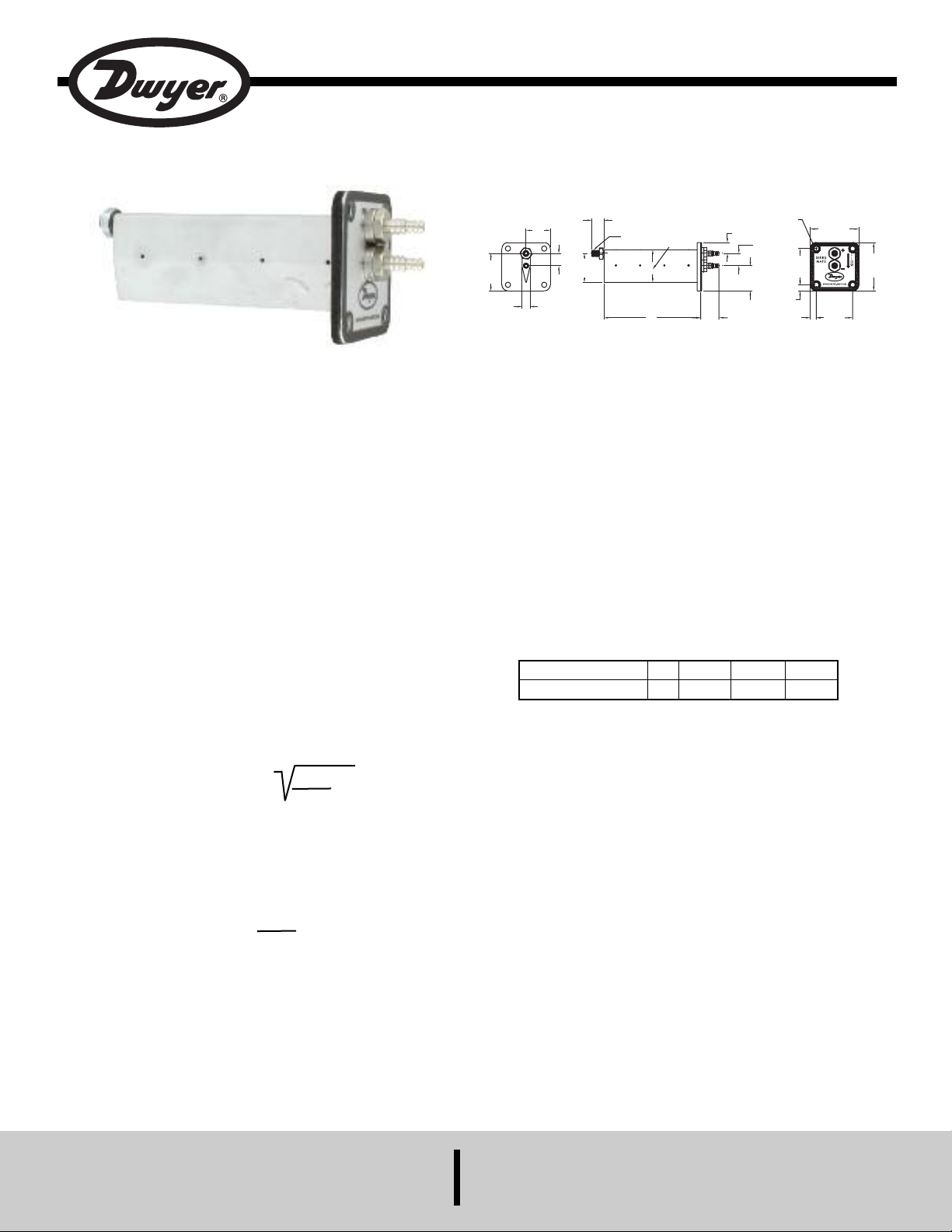
Series MAFS Averaging Flow Sensor
Specifications - Installation and Operating Instructions
*L dimension = length of part designated in model.
The Series MAFS Averaging Flow Sensor uses evenly distributed total
and static pressure measuring points to deliver an accurate
measurement of flows in a duct. The Air Flow Measuring Probe can be
completely installed from outside of the duct making it very easy to
install. With its lightweight and durable construction in addition to its
ease of installation, this product lends itself to being used in the HVAC
industry. These air flow measuring probes may be ordered to fit into
either round or rectangular duct installations.
INSTALLATION
When you unpack the Series MAFS Averaging Flow Sensor ensure that
there is no visible damage from shipping. Inspect each sensing point on
the probes to ensure that they are not filled with debris from shipping. If
there is obvious shipping damage, the probe must be replaced prior to
use in order to avoid inaccurate measurements. Please contact Dwyer
Instruments, Inc. if it is necessary to replace your air flow measurement
probe.
Location - The sensor should be installed in the flowing line with as
much straight run upstream as possible. A rule of thumb is to allow 10 15 diameters upstream and 5 downstream. The table below lists
recommended up and down piping.
CALCULATING VELOCITY
Air Velocity = 1096.2 (Cp) P
where:
P
= Sensed pressure difference (velocity pressure)
v
v
D
in inches of water column
D = Air density in lbs./ft.3(dry air = .075)
Cp = Pitot tube coefficient: See specifications for
K-factor vs. size
Air Density = 1.325 X
PB
T
PB= Barometric pressure in inches of mercury
T = Absolute Temperature (Indicated Temperature in °F
plus 460)
SPECIFICATIONS
Service: Clean air.
Wetted Materials: Aluminum AA6063.
Accuracy: 0 to 9000 FPM (45.7 m/s); ±2% FS, ±3% FS for 6˝ and 48˝
length models.
K-Factor: 0.81, 0.80 for 6˝ and 48˝ lengths, 4˝ length=0.82.
Max. Temperature: 400°F (204°C); Gasket: -31 to 230°F (-35 to 110°C).
Minimum Design Flow: 400 fpm (2.03 m/sec).
Maximum Design Flow: 12,000 fpm (60.96 m/sec).
Process Connections: 1/4˝ barb.
Straight Run Requirements: 5 diameters or longest side dimensions.
RECTANGULAR DUCT MODELS
Determining Probe Number and Placement for Rectangular Ducts
1. To determine the number of probes you need please consult the
chart below.
Short Duct Dimension
Number of Probes
<12˝
1
12˝ - 23˝
2
24˝ - 35˝
3
36˝ - 48˝
4
2. In order to determine where to place your probes, divide the short
duct dimension by number of probes.
3. Divide the result by two and this will be the distance from the top
edge of the duct to the first probe location.
4. The next probe will be placed two times the resulting distance from
step two from the first probe. So, if the first probe was placed 4˝ from
the top edge of the duct, your next probe would be placed 8” from the
first probe, or 12˝ from the top of the duct.
5. Continue this pattern until you have determined all probe locations.
Example: You have a duct with a 24˝ short side, and upon consulting the
chart determined that you needed 3 probes for this size duct.
24 / 3 = 8
8 / 2 = 4
Therefore, the first probe is placed 4˝ from the top of the duct.
The second probe is placed 4˝ + 8˝ = 12˝ from the top of the duct.
The third probe is placed 4˝ + (2 x 8˝) = 20˝ from the top of the duct.
DWYER INSTRUMENTS, INC.
P.O. BOX 373 • MICHIGAN CITY, INDIANA 46360, U.S.A. Fax: 219/872-9057 e-mail: info@dwyer-inst.com
Phone: 219/879-8000 www.dwyer-inst.com
Page 2
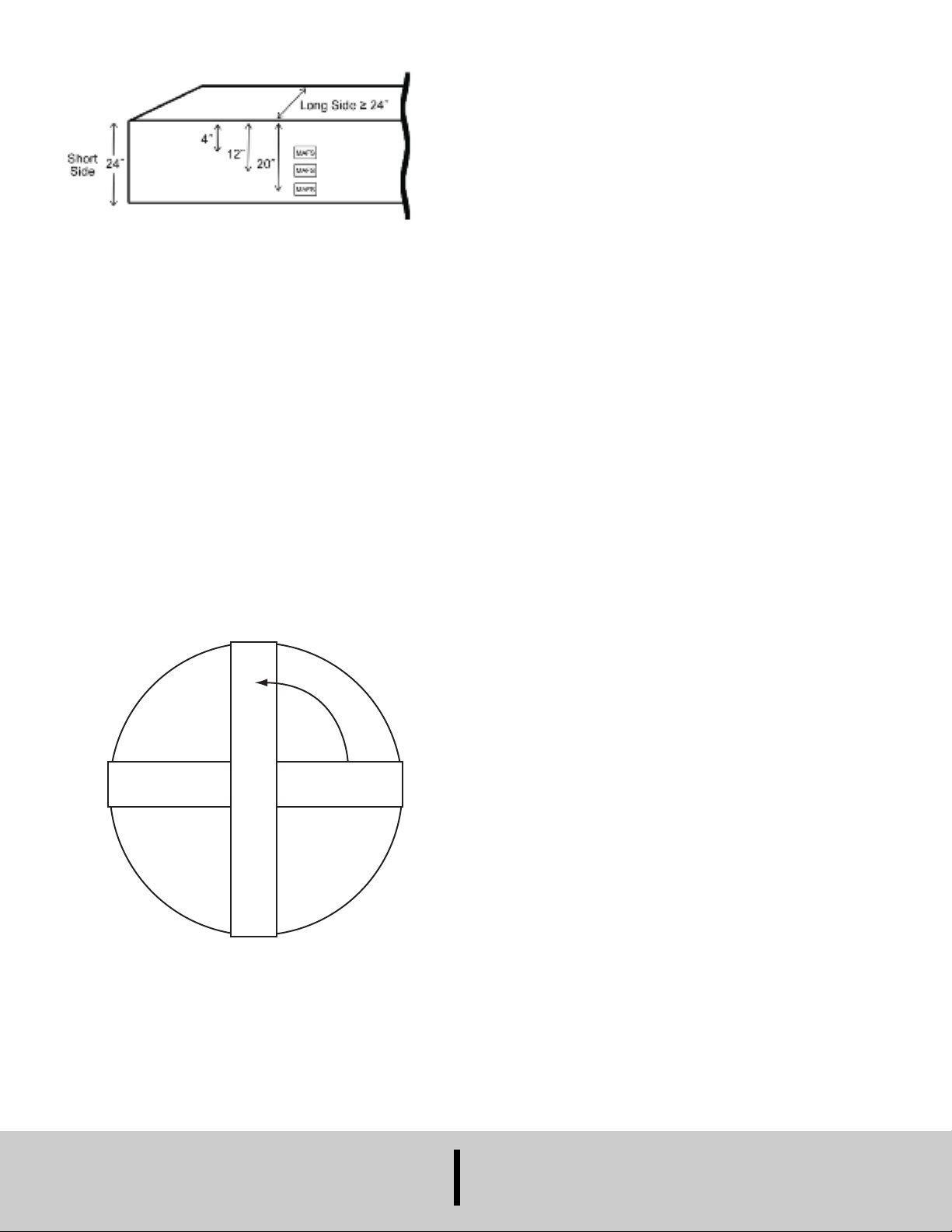
Figure 1: View illustration of probe placement example.
DAFM
D
A
F
M
90°
Please note that all probes should be installed vertically and
running parallel to each other if installed in a rectangular duct.
RECTANGULAR DUCT PROBE INSTALLATION
1. See drawing for proper opening to cut for insertion. Cut a hole at
locations calculated above in side of duct. Drill a 5/16˝ hole on
opposite side of duct. Remove o-ring, hex and acorn nuts.
2. Place silicon bead around holes.
3. Slide MAFS into holes and screw the included four self drilling
screws into duct to attach MAFS. On far end, re-attach o-ring, hex
and acorn nuts.
4. Connect 3/16˝ I.D. tubing to barb fittings on MAFS.
5. Check all fittings and tubing connections for leaks using a leak
detector.
6. Tee all high and low ports into one high and one low line and connect
to transmitter or gage.
7. The devices should be checked occassionally for build-up of dirt of
debris common in an HVAC system.
CIRCULAR DUCT MODELS
Determining Probe Number and Location for Round Ducts
1. Note that in round ducts only two probes are needed. The quantity
of probes needed does not depend on size of the duct.
2. Locate probes 90 degrees apart. See Figure 2 for an example.
ROUND DUCT PROBE INSTALLATION
1. See drawing for proper opening to cut for insertion. Cut a hole at
locations calculated above in side of duct. Drill a 5/16˝ hole on
opposite side of duct. Remove o-ring, hex and acorn nuts.
2. Place silicon bead around holes.
3. Slide MAFS into holes and screw four self drilling screws into duct to
attach MAFS. On far end, re-attach o-ring, hex and acorn nuts.
4. Connect 3/16˝ I.D. tubing to barb fittings on MAFS.
5. Check all fittings and tubing connections for leaks using a leak
detector.
6. Tee all high and low ports into one high and one low line and connect
to transmitter or gage.
7. The devices should be checked occassionally for build-up of dirt or
debris common in an HVAC system.
CALIBRATION
Sometimes field calibration may be required if the probe is installed in a
bad location i.e. immediately downstream of an elbow. In order to
calibrate, you must either perform a traverse of the duct or a sum of the
air registers and compare this with the MAFS output. Then, you must
make the correction to the effective area in the computer to make up for
the error.
MAINTENANCE/REPAIR
Upon final installation of the Series MAFS, no routine maintenance is
required. The Series MAFS is not field serviceable and should be
returned if repair is needed. Field repair should not be attempted and
may void warranty.
WARRANTY/RETURN
Refer to “Terms and Conditions of Sales” in our catalog and on our
website. Contact customer service to receive a Return Goods
Authorization number before shipping the product back for repair. Be
sure to include a brief description of the problem plus any additional
application notes.
M
A
F
S
MAFS
Figure 2: Cross-sectional view of probe placement in a round duct.
©Copyright 2012 Dwyer Instruments, Inc. Printed in U.S.A. 4/12 FR# 72-444019-00 Rev. 1
DWYER INSTRUMENTS, INC.
Phone: 219/879-8000 www.dwyer-inst.com
P.O. BOX 373 • MICHIGAN CITY, INDIANA 46360, U.S.A. Fax: 219/872-9057 e-mail: info@dwyer-inst.com
 Loading...