

Page 1
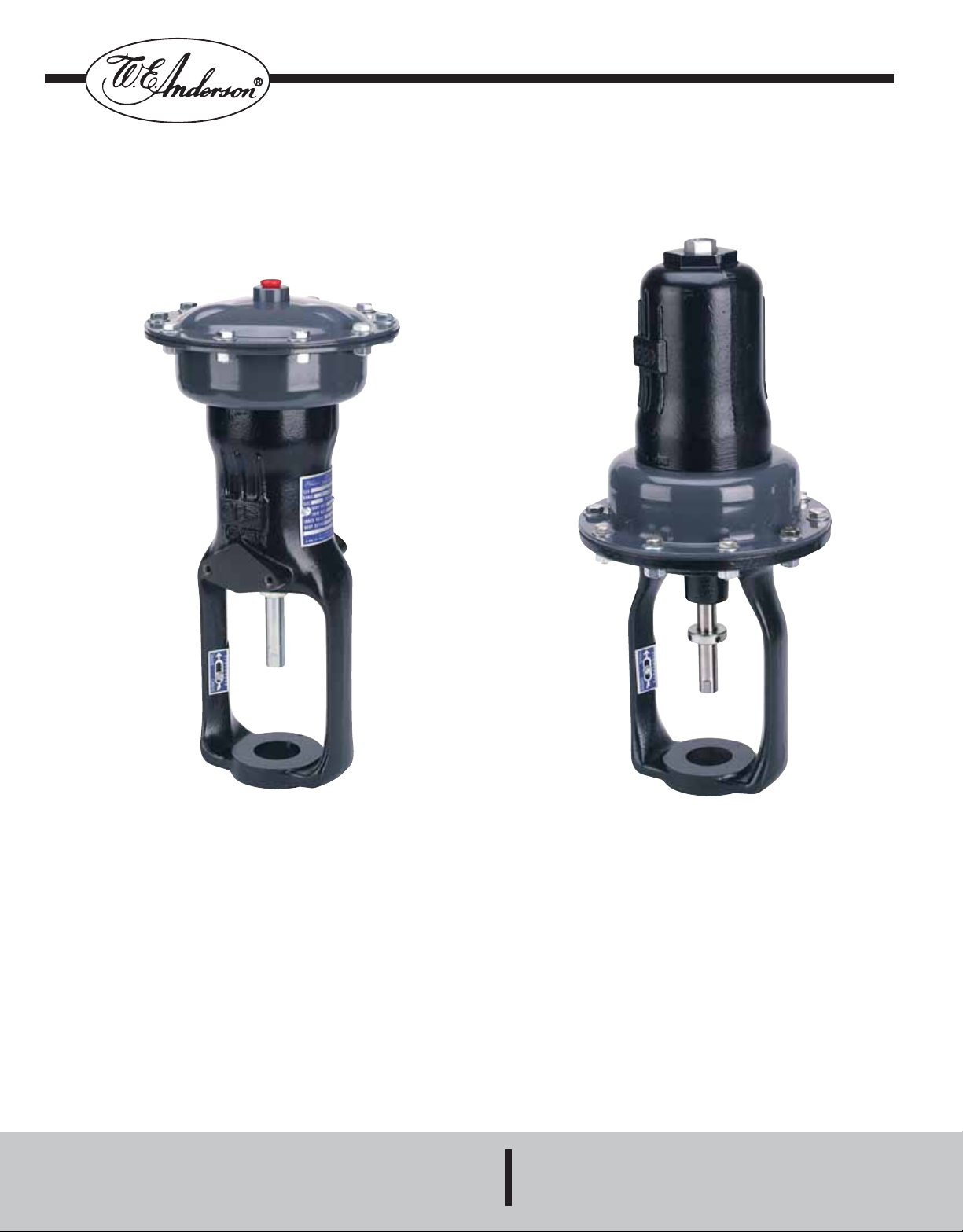
LIN-E-AIRE®Valve Actuators
Specifications - Installation and Operating Instructions
Push-to-Close
Termination Nos. 220 thru 223, 240 thru 244
Push-to-Open
Termination Nos. 230, 231, 233, 250 thru 254
Bulletin IB-5A103
Push-to-Close
NOTICE: Information in this manual is intended only to assist our customers in the efficient operation of our equipment. Use of this manual for any other pur-
pose is specifically prohibited and its contents are not to be reproduced in full or part without prior approval.
Use of the DANGER, WARNING, CAUTION and NOTE
This publication includes DANGER, WARNING, CAUTION and NOTE information where appropriate to point out safety related or other important information.
DANGER - Hazards which will result in severe personal injury or death.
WARNING - Hazards which could result in personal injury.
CAUTION - Hazards which could result in equipment or property damage.
NOTE - Alerts user to pertinent facts and conditions.
Although DANGER and WARNING hazards are related to personal injury, and CAUTION hazards are associated with equipment or pr operty damage, it should
be understood that operation of damaged equipment could, under certain operational conditions, result in degraded process system performance leading to
personal injury or death. Therefore, comply fully with all DANGER, WARNING, and CAUTION notices.
W.E. ANDERSON DIV., DWYER INSTRUMENTS, INC.
P.O. BOX 358 • MICHIGAN CITY, INDIANA 46361 U.S. A.
1
Phone: 219/879-8000 www.dwyer-inst.com
Fax: 219/872-9057 e-mail: info@dwyer-inst.com
Push-to-Open
Page 2

TABLE OF CONTENTS
1 INTRODUCTION . . . . . . . . . . . . . . . . . . . . . . . . . . . . . . . . . . . . . . . . . . . . . . . . . . . . . . . . . . . . . . . . . . . . . . . . . . . . . . .3
1.1 Description . . . . . . . . . . . . . . . . . . . . . . . . . . . . . . . . . . . . . . . . . . . . . . . . . . . . . . . . . . . . . . . . . . . . . . . . . . . . . . . . . . .3
1.2 Catalog Numbers . . . . . . . . . . . . . . . . . . . . . . . . . . . . . . . . . . . . . . . . . . . . . . . . . . . . . . . . . . . . . . . . . . . . . . . . . . . . . .4
1.3 Specifications . . . . . . . . . . . . . . . . . . . . . . . . . . . . . . . . . . . . . . . . . . . . . . . . . . . . . . . . . . . . . . . . . . . . . . . . . . . . . . . . .5
2 INSTALLATION . . . . . . . . . . . . . . . . . . . . . . . . . . . . . . . . . . . . . . . . . . . . . . . . . . . . . . . . . . . . . . . . . . . . . . . . . . . . . . . .5
2.1 Mounting . . . . . . . . . . . . . . . . . . . . . . . . . . . . . . . . . . . . . . . . . . . . . . . . . . . . . . . . . . . . . . . . . . . . . . . . . . . . . . . . . . . .5
2.2 Pneumatic Connections . . . . . . . . . . . . . . . . . . . . . . . . . . . . . . . . . . . . . . . . . . . . . . . . . . . . . . . . . . . . . . . . . . . . . . . . .5
3 OPERATION . . . . . . . . . . . . . . . . . . . . . . . . . . . . . . . . . . . . . . . . . . . . . . . . . . . . . . . . . . . . . . . . . . . . . . . . . . . . . . . . . .6
3.1 Checking Valve Travel . . . . . . . . . . . . . . . . . . . . . . . . . . . . . . . . . . . . . . . . . . . . . . . . . . . . . . . . . . . . . . . . . . . . . . . . . .6
3.2 Adjusting Actuator Range . . . . . . . . . . . . . . . . . . . . . . . . . . . . . . . . . . . . . . . . . . . . . . . . . . . . . . . . . . . . . . . . . . . . . . .7
3.2.1 Air-to-Lower Actuator . . . . . . . . . . . . . . . . . . . . . . . . . . . . . . . . . . . . . . . . . . . . . . . . . . . . . . . . . . . . . . . . . . . . . . . . .7
3.2.2 Air-to-Raise Actuator . . . . . . . . . . . . . . . . . . . . . . . . . . . . . . . . . . . . . . . . . . . . . . . . . . . . . . . . . . . . . . . . . . . . . . . . . .7
4 MAINTENANCE . . . . . . . . . . . . . . . . . . . . . . . . . . . . . . . . . . . . . . . . . . . . . . . . . . . . . . . . . . . . . . . . . . . . . . . . . . . . . . .8
4.1 Test Equipment and Tools Required . . . . . . . . . . . . . . . . . . . . . . . . . . . . . . . . . . . . . . . . . . . . . . . . . . . . . . . . . . . . . . . .8
4.2 Adjusting Valve Plug Travel . . . . . . . . . . . . . . . . . . . . . . . . . . . . . . . . . . . . . . . . . . . . . . . . . . . . . . . . . . . . . . . . . . . . . . .8
4.2.1 Push-to-Close Valve with Air-to-Lower Actuator . . . . . . . . . . . . . . . . . . . . . . . . . . . . . . . . . . . . . . . . . . . . . . . . . . . . .8
4.2.2 Push-to-Close Valve with Air-to-Raise Actuator or Push-to-Open Valve with Air-to-Lower Actuator . . . . . . . . . . . . . .8
4.3 Replacing Actuator Diaphragm . . . . . . . . . . . . . . . . . . . . . . . . . . . . . . . . . . . . . . . . . . . . . . . . . . . . . . . . . . . . . . . . . . .8
4.3.1 Air-to-Lower Actuator . . . . . . . . . . . . . . . . . . . . . . . . . . . . . . . . . . . . . . . . . . . . . . . . . . . . . . . . . . . . . . . . . . . . . . . . .8
4.3.2 Air-to-Raise Actuator . . . . . . . . . . . . . . . . . . . . . . . . . . . . . . . . . . . . . . . . . . . . . . . . . . . . . . . . . . . . . . . . . . . . . . . . . .9
4.4 Changing Range Spring . . . . . . . . . . . . . . . . . . . . . . . . . . . . . . . . . . . . . . . . . . . . . . . . . . . . . . . . . . . . . . . . . . . . . . . . .9
4.4.1 Air-to-Lower Actuator . . . . . . . . . . . . . . . . . . . . . . . . . . . . . . . . . . . . . . . . . . . . . . . . . . . . . . . . . . . . . . . . . . . . . . . . .9
4.4.2 Air-to-Raise Actuator . . . . . . . . . . . . . . . . . . . . . . . . . . . . . . . . . . . . . . . . . . . . . . . . . . . . . . . . . . . . . . . . . . . . . . . . . .9
ILLUSTRATIONS
Fig. 1 Air-to-Lower Actuator . . . . . . . . . . . . . . . . . . . . . . . . . . . . . . . . . . . . . . . . . . . . . . . . . . . . . . . . . . . . . . . . . . . . . . . . .3
Fig. 2 Air-to-Raise Actuator . . . . . . . . . . . . . . . . . . . . . . . . . . . . . . . . . . . . . . . . . . . . . . . . . . . . . . . . . . . . . . . . . . . . . . . . .3
Fig. 3 Mounting Dimensions for Air-to-Lower Actuator . . . . . . . . . . . . . . . . . . . . . . . . . . . . . . . . . . . . . . . . . . . . . . . . . . . . .6
Fig. 4 Mounting Dimensions for Air-to-Raise Actuator . . . . . . . . . . . . . . . . . . . . . . . . . . . . . . . . . . . . . . . . . . . . . . . . . . . . .6
Fig. 5 Travel Indicator Plate Showing Valve Plug Travel . . . . . . . . . . . . . . . . . . . . . . . . . . . . . . . . . . . . . . . . . . . . . . . . . . . . .6
Fig. 6 Adjusting Actuator Range . . . . . . . . . . . . . . . . . . . . . . . . . . . . . . . . . . . . . . . . . . . . . . . . . . . . . . . . . . . . . . . . . . . . . .7
Fig. 7 Adjusting Valve Plug Travel . . . . . . . . . . . . . . . . . . . . . . . . . . . . . . . . . . . . . . . . . . . . . . . . . . . . . . . . . . . . . . . . . . . . .8
Fig. 8 Disassembly of Air-to-Lower Actuator . . . . . . . . . . . . . . . . . . . . . . . . . . . . . . . . . . . . . . . . . . . . . . . . . . . . . . . . . . .10
Fig. 9 Disassembly of Air-to-Raise Actuator . . . . . . . . . . . . . . . . . . . . . . . . . . . . . . . . . . . . . . . . . . . . . . . . . . . . . . . . . . . .11
TABLES
1 Air-to-Lower Actuator . . . . . . . . . . . . . . . . . . . . . . . . . . . . . . . . . . . . . . . . . . . . . . . . . . . . . . . . . . . . . . . . . . . . . . . . . . . .5
2 Air-to-Raise Actuator . . . . . . . . . . . . . . . . . . . . . . . . . . . . . . . . . . . . . . . . . . . . . . . . . . . . . . . . . . . . . . . . . . . . . . . . . . . . .5
3 Maximum Air Supply Pressure and Maximum Stroke . . . . . . . . . . . . . . . . . . . . . . . . . . . . . . . . . . . . . . . . . . . . . . . . . . . .5
4 Tools Required . . . . . . . . . . . . . . . . . . . . . . . . . . . . . . . . . . . . . . . . . . . . . . . . . . . . . . . . . . . . . . . . . . . . . . . . . . . . . . . . .8
2
Page 3
1. INTRODUCTION
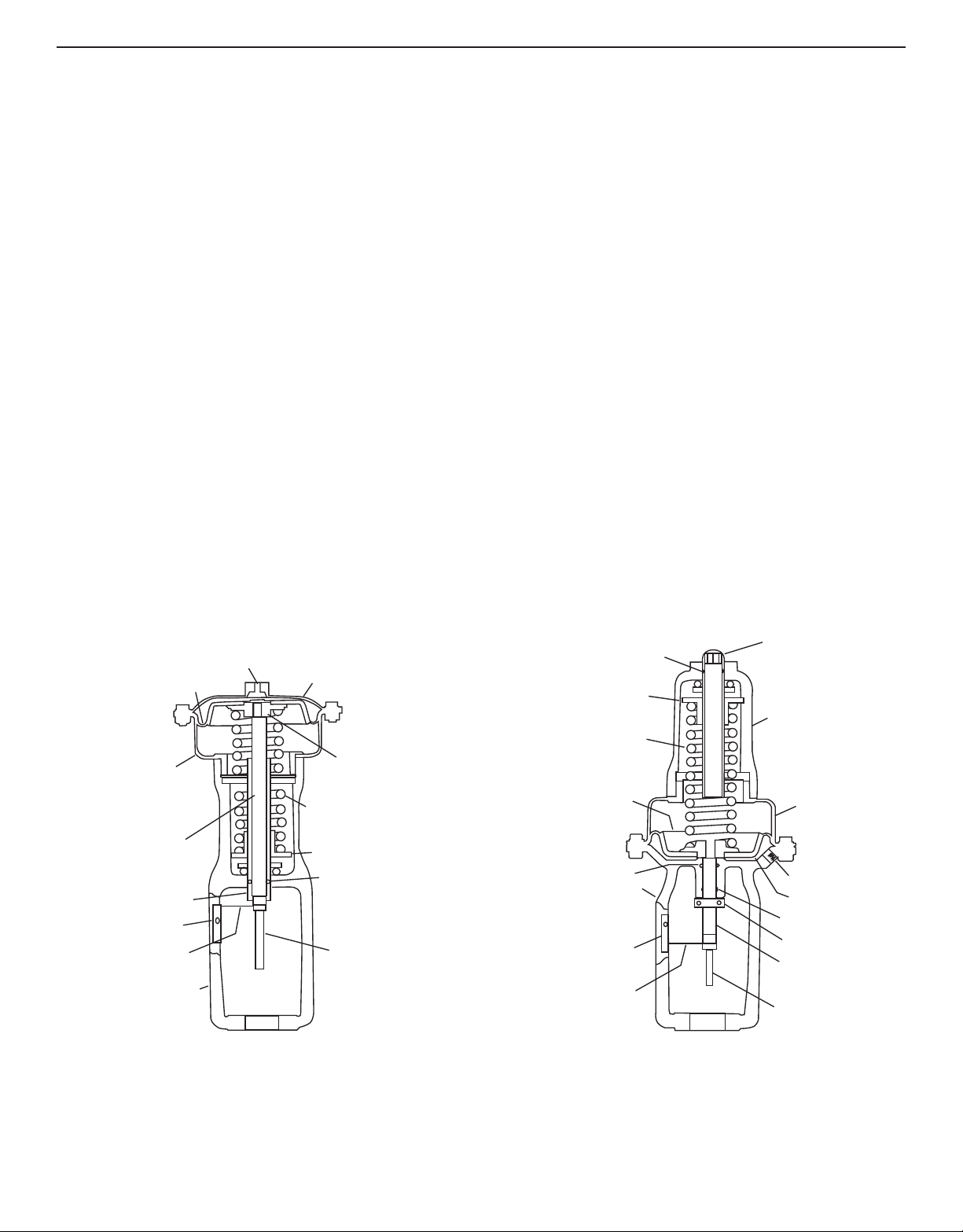
O-Ring
Spring Seat
Range Spring
Push Plate
Assembly
Upper Diaphragm
Casing
1/4˝ NPT
Input Connection
Diaphragm
Lower Diaphragm
Casing
Push Rod
Range Spring
Adjusting Screw
Travel Indicator
Plate
Travel Indicator
Yoke
Valve Stem
Range Spring
Adjusting Screw
Spring Casing
Diaphragm
Casing
1/4˝ NPT
Input Conn.
Diaphragm
O-Ring
Travel Stop
Collar
Push Rod
Valve Stem
Travel Indicator
Travel Indicator
Plate
Yoke
V-Packing
Push Plate
Range Spring
Spring Seat
O-Ring
1.1 DESCRIPTION
The Lin-E-Aire
tion of the control valve. The opening, closing or throttling of the
valve plug in the valve body is accomplished by varying the air
pressure to the diaphragm in the actuator. This pressure is transmitted from a control device, which may be controlling pressure,
liquid level, temperature or flow.
®
Valve Actuators are used for automatic opera-
Thus, by selection of actuator and control valve plug action,
either push-to-close or push-to-open, the control valve will either
open or close on failure of air pressure to diaphragm.
The spring and diaphragm are completely enclosed to protect
them from dust, dirt and other foreign matter. Spring adjustments
are made with a ball bearing spring adjustment sleeve.
Diaphragm and spring assembly may easily be removed for
replacement or substitution.
Two types of actuators are used for process control, the choice
of either depends upon the valve action desired in case of air
supply failure. There are two types
Air-to-Lower - Termination Nos. 220 thru 223, 240 thru 244,
Figure 1. In this type of actuator, air pressure moves the push rod
downward compressing the spring. In the event of air failure, the
push rod moves to its extreme upward position.
Air-to-Raise - Termination Nos. 230, 231, 233, 250 thru 254,
Figure 2. In this type of actuator, air pressure moves the push rod
upward compressing the spring. In the event of air failure, the
push rod moves to its extreme downward position.
The construction and operating range are listed on the data plate
mounted on actuator. Actuator size and spring are selected to
meet the requirements of the application. In service the actuator
should create full travel of the valve plug when the pressure range
indicated on data plate is applied. This pressure range is most
generally 3 to 15 psi (20 to 100 kPa), but other ranges are available.
For precise control of valve plug position or where two valves are
to be operated in sequence by one control device, a W.E.
Anderson valve positioner, Catalog Number 100N or 165, is recommended.
Figure 1. Air-to-Lower Actuator
Figure 2. Air-to-Raise Actuator
3
Page 4

1.2 Catalog Numbers
Control Valves - Hi-Flow™ Series Model Chart
Example 2 00 1 V A 3 2 230 LO
2001VA32-230-LO Hi-Flow™Globe Valve; 2-way, 3/4˝ NPT connection, linear plug, bronze body, 316 SS trim, reduced port 1/2˝ size.
Configuration 2
3
Valve Body
Action
00
01
0
1
2
3
Connection
Size
4
5
6
7
8
Valve Seat V
Valve Plug
Type
Valve Body
Material
W
2-way
3-way
Push-To-Close
Push-To-Open (2-way only)
1/2˝ NPT
3/4˝ NPT
1˝ NPT
1-1/4˝ NPT
1-1/2˝ NPT (or Flange with LRF or HRF option)
2˝ NPT (or Flange with LRF or HRF option)
2-1/2˝ Flange (see options)
3˝ Flange (see options)
4˝ Flange (see options)
Single Seat (2-way only)
Double Seat (3-way only)
A
L
S
N
1
3
4
Linear
Linear Needle (2000 to 2002 only)
Equal Percentage (2000 to 2005 only)
Equal Percentage Needle (2000 to 2002 only)
Ductile Iron
Bronze
316 SS
Trim
Material
Actuator
Needle Plug
Port Size
Options
2 316 SS
220
221
222
223
230
231
233
2
3
4
5
6
7
8
9
Air-To-Lower, 20 in
Air-To-Lower, 45 in
Air-To-Lower, 45 in
Air-To-Lower, 80 in
Air-To-Raise, 20 in2 (2-way only)
Air-To-Raise, 45 in
Air-To-Raise, 80 in
1/8˝ for Type N valve plug
3/16˝ for Type N valve plug
1/4˝ for Type N valve plug
5/16˝ for Type N valve plug
3/8˝ for Type N valve plug
1/32˝ for Type L valve plug
1/16˝ for Type L valve plug
3/32˝ for Type L valve plug
A
Positioner factory mounted
(specify positioner model)
L0
Reduced port: 3/4˝ to 1/2˝ port size (2001 only)
Reduced port: 1˝ to 1/2˝ port size (2002 only)
L1
Reduced port: 1˝ to 3/4˝ port size (2002 only)
Z
Special operating range (2-10 psi, 10-18 psi)
LRF
Low Range Flange: Class 125 in Iron or Class 150 Bronze, 316 SS
body (for 1-1/2˝ and 2˝ sizes only, standard on 2-1/2˝, 3, and 4˝ size)
HRF
High Range Flange: Class 250 in Iron or Class 300 in Bronze, 316
SS body (for 1-1/2˝ to 4˝ sizes)
2
2
2
2
2
(2-way only)
2
(2-way only)
4
Page 5

1.3 Specifications
Table 1. Air-to-Lower Actuator
Standard Actuator
Boss
Dia.
1-1/2˝
1-15/16˝
2-1/8˝
2-13/16˝
2-13/16˝
Table 2. Air-to-Raise Actuator
Boss
Dia.
1-1/2˝
1-15/16˝
2-1/8˝
2-13/16˝
2-13/16˝
Term.
No.
220
222
240
242
244
Term.
No.
230
250
252
254
Part
No.
15S620
15S622
15S640
15S642
15S644
Standard Actuator
Part
No.
15S630
15S650
15S652
15S654
ACTUATOR MATERIALS
Frame: Cast Iron, Baked Enamel Finish.
Diaphragm Case: Steel, Baked Enamel Finish.
Diaphragm: Buna-N-rubber, Nylon reinforced.
Range Spring: Plated spring steel.
Range Spring Seat: Plated steel.
Adjusting Screw: Plated cold rolled steel.
Push Rod: Plated steel.
AMBIENT TEMPERATURE LIMITS
-32 to 150°F (-36 to 66°C).
MAXIMUM ACTUATOR AIR PRESSURE
Refer to Table 3.
AIR CONNECTION: 1/4˝ female NPT.
No. of
Bolts
10
12
12
12
18
No. of
Bolts
10
10
12
18
Effective
Area
20 sq. in.
45 sq. in.
20 sq. in.
45 sq. in.
80 sq. in.
Effective
Area
20 sq. in.
20 sq. in.
45 sq. in.
80 sq. in.
Senior Actuator
Term
No.
221
223
241
243
-
Term
No.
231
233
251
253
-
Table 3. Maximum Air Supply Pressure and Maximum Stroke
Termination
Number
220
240
221
241
222
242
223
Air-to-Lower
243
244
230
250
231
233
251
252
Air-to-Raise
253
254
15S621
15S623
15S641
15S643
15S631
15S633
15S651
15S653
Part No.
Standard
15S620
15S640
15S621
15S641
15S622
15S642
15S623
15S643
15S644
15S630
15S650
15S631
15S633
15S651
15S652
15S653
15S654
Part
No.
-
Senior Actuator
Part
No.
-
Max. Air Supply
psig kPa
100
100
50
50
100
100
50
50
70
100
100
50
50
50
100
50
70
No. of
Bolts
12
18
12
18
-
No. of
Bolts
12
18
12
18
-
Pressure
700
700
350
350
700
700
350
350
480
700
700
350
350
350
700
350
480
Effective
Area
45 sq. in.
80 sq. in.
45 sq. in.
80 sq. in.
-
Effective
Area
45 sq. in.
80 sq. in.
45 sq. in.
80 sq. in.
-
Max. Stroke
Inches
1
1
1
1
1-1/2
1-1/2
1-1/2
1-1/2
2-1/4
1
1
1
1-1/2
1
1-1/2
1-1/2
2-1/4
mm
25.4
25.4
25.4
25.4
38.1
38.1
38.1
38.1
57.2
25.4
25.4
25.4
38.1
25.4
38.1
38.1
57.2
MAXIMUM STROKE
Refer to Table 3.
2. INSTALLATION
2.1 Mounting - The Lin-E-Aire®Valve Actuator is normally fur-
nished mounted on a valve body. Follow the valve body instructions when installing the control valve in the pipeline.
Clearance should be left above and below the control valve to
permit removal of actuator and valve plug. Removal clearance
dimensions are specified in the control valve instructions, as well
as installation instructions. The actuator will sometimes be
shipped alone for field mounting on a valve body. Mount actuator
as outlined in the control valve instructions.
2.2 Pneumatic Connections - Connect the input pressure to
the 1/4˝ female NPT port on the top of an air-to-lower actuator or
under the diaphragm casing on an air-to-raise actuator, Figure 3
or 4. Either pipe or tubing may be used for the air line. The input
pressure must not exceed the limits listed under the specifications.
When there is a long distance between the actuator and the control device which produces the input pressure, or when a large
actuator size is required, there may be excessive transmission lag
in the control signal. A W.E. Anderson Valve Positioner, Catalog
Number 100N or 165, can be used to reduce the lag. If a valve
positioner is included with the actuator, connections between the
positioner and actuator are made at the factory. Refer to the valve
positioner instructions for additional connection information.
5
Page 6

Input Conn.
1/4˝ female NPT
Input Conn.
1/4˝ female NPT
Valve Body
Dimension
Figure 3. Mounting Dimension for Air-to-Lower Actuator
Standard Actuator in. (mm)
Part
Term
No.
No.
15S620
220
15S622
222
15S640
240
15S642
242
15S644
244
Senior Actuator in. (mm)
Part
Term
No.
No.
15S621
221
15S623
223
15S641
241
15S643
243
For reference only; not for construction.
X
7-3/4 (196.85)
10-5/8 (269.86)
7-3/4 (196.85)
10-5/8 (269.86)
13-3/8 (339.73)
X
10-5/8 (269.86)
13-3/8 (339.73)
10-5/8 (269.86)
13-3/8 (339.73)
15-7/8 (403.23)
18-5/8 (473.08)
15-7/8 (403.23)
18-5/8 (473.08)
22-5/8 (574.68)
16-9/16 (420.69)
20 (508.00)
16-9/16 (420.69)
20 (508.00)
No. of
Y
Y
Bolts
No. of
Bolts
10
1-1/2 (38.10)
12
1-15/16 (49.21)
10
2-1/8 (53.98)
12
2-13/16 (71.44)
18
2-13/16 (71.44)
12
1-1/2 (38.10)
18
1-15/16 (49.21)
12
2-1/8 (53.98)
18
2-13/16 (71.44)
Yoke Boss
Hole Diam.
Yoke Boss
Hole Diam.
3. OPERATION
3.1 Check Valve Travel - The actuator spring has been select-
ed to meet the requirements of the application and has been
adjusted at the factory to the pressure range stamped on the
data plate. The spring has a constant rate of compression, and
adjustments shift the pressure span up or down to make stem
travel coincide with this pressure range. When in service, the
actuator should yield the required travel when pressure range
stamped on data plate is applied. This diaphragm pressure range
is generally 3 to 15 psi (20 to 100 kPa), but other ranges may be
used.
Valve Body
Dimension
Figure 4. Mounting Dimension for Air-to-Raise Actuator
Standard Actuator in. (mm)
Part
Term
No.
No.
15S630
230
15S650
250
15S652
252
15S654
254
Senior Actuator in. (mm)
Part
Term
No.
No.
15S631
231
15S633
233
15S651
251
15S653
253
For reference only; not for construction.
X
7-3/4 (196.85)
7-3/4 (196.85)
10-5/8 (269.86)
13-3/8 (339.73)
X
10-5/8 (269.86)
13-3/8 (339.73)
10-5/8 (269.86)
13-3/8 (339.73)
17-3/16 (436.56)
17-3/16 (436.56)
20-3/4 (527.05)
32-7/32 (818.36)
Y
17-13/16 (452.44)
22-9/32 (565.94)
17-13/16 (452.44)
22-9/32 (565.94)
No. of
Y
Bolts
No. of
Bolts
10
1-1/2 (38.10)
12
2-1/8 (53.98)
12
2-13/16 (71.44)
18
3-9/16 (90.49)
12
1-1/2 (38.10)
18
1-1/2 (38.10)
12
2-1/8 (53.98)
18
2-13/16 (71.44)
Yoke Boss
Hole Diam.
Yoke Boss
Hole Diam.
When the actuator is completely installed and connected to the
control device, it should be checked with normal working line
pressure conditions for correct travel. Apply the pressure range
listed on the data plate to the actuator. Note that travel indicator
should have moved the distance marked on indicator plate,
Figure 5.
The pressure drop across the valve body ports has a direct effect
on the actual operating pressure range. In some instances, the
valve operating range may be different from the indicated range.
This is because the pressure conditions in the valve body are different from those originally specified and for which the control
valve has been set at the factory. If this difference is small, a
spring adjustment is all that is required to obtain correct operating range, refer to Adjusting Actuator Range.
Figure 5. Travel Indicator Plate Showing Valve Plug Travel
6
Page 7

3.2 Adjusting Actuator Range
Note: When using this procedure, be sure that the valve is oper-
ating under normal line pressure conditions.
3.2.1 Air-to-Lower Actuator
1. Slowly increase input pressure until stem just begins to move.
Stem motion can be accurately detected by feeling stem or push
rod as pressure is applied.
WARNING: If valve is used for steam service or where line
process is hot, use visual means of detecting movement to avoid
injury.
2. Note input pressure at which stem moves.
3. If input pressure is not the same as lower range value on data
plate, spring adjusting screw must be adjusted.
If pressure is high, turn adjusting screw, Figure 6, counter-
clockwise as viewed from the valve top.
If pressure is low, turn adjusting screw clockwise as viewed
from the valve top.
4. Release input pressure and repeat Steps 1, 2 and 3 until stem
moves at the lower range value.
3.2.2 Air-to-Raise Actuator
1. Loosen the four set screws on travel stop collar, Figure 6, collar should move freely on push rod.
2. Slowly increase input pressure until stem just begins to move.
Stem motion can be accurately detected by feeling stem or push
rod as pressure is applied.
WARNING: If valve is used for steam service or where line
process is hot, use visual means of detecting movement to avoid
injury.
3. Note input pressure at which stem moves.
4. If input pressure is not the same as lower range value on data
plate, spring adjusting screw must be adjusted.
If pressure is high, turn adjusting screw clockwise as viewed
from the valve top.
If pressure is low, turn adjusting screw counterclockwise as
viewed from the valve top.
5. Release input pressure and repeat Steps 2, 3 and 4 until valve
stem moves at lower range value.
6. Apply the upper range value input pressure stamped on data
plate. Slide travel stop collar up on push rod right to yoke and
tighten the four set screws.
Figure 6. Adjusting Actuator Range
7
Page 8

4. MAINTENANCE
4.1 Test Equipment and Tools Required - The only test equip-
ment required for valve and actuator maintenance is an air supply source, gage and regulator. The tools required are shown in
Table 4.
Table 4. Tools Required
Actuator
Size
All
Tool
Screwdriver
Open End
Wrenches
Size
3/16 in.
1/4 in.
1/2 in.
9/16 in.
5/8 in.
7/8 in.
1-1/4 in.
1-1/2 in.
1-15/16 in.
9/16 in.
11/16 in.
13/16 in.
31/32 in.
1 in.
Use
Travel Indicator Plate
Diaphragm Casing
Mounting Screw & Nut
Range Spring
Adjusting Screw
Actuator Push Rod
Note: If pressure range required to obtain full valve plug travel
does not agree with range stamped on data plate, refer to 3.2
Adjusting Actuator Range.
4.2.2 Push-to-Close Valve with Air-to-Raise Actuator or
Push-to-Open Valve with Air-to-Lower Actuator
1. Apply air pressure to actuator to fully open valve and note location of travel indicator.
2. If indicator is not at travel marks on plate, Figure 5, measure
distance between indicator and mark.
CAUTION: Do not make any adjustment when valve plug is on
its seat.
3. Loosen stem locknut, Figure 7. Grip valve stem near threads,
and turn stem to move valve plug the distance measured in Step
2.
4. Position indicator toward travel indicator plate and tighten
valve stem locknut.
5. Vent all pressure from actuator.
6. Repeat Step 1 thru 5 until travel indicator is at travel marks
when valve is fully opened.
Note: If pressure range required to obtain full valve plug travel
does not agree with range stamped on data plate, refer to 3.2
Adjusting Actuator Range.
Figure 7. Adjusting Valve Plug Travel
4.2 Adjusting Valve Plug Travel - The purpose of this proce-
dure is to adjust the length of valve stem engagement in the push
rod so that the travel indicator is at the travel marks on the indicator plate when valve is fully closed.
4.2.1 Push-to-Close Valve with Air-to-Lower Actuator
1. Apply air pressure to actuator to fully close valve and note
location of travel indicator.
2. If indicator is not at travel marks on plate, Figure 5, measure
distance between indicator and mark.
CAUTION: Do not make any adjustments when valve plug is on
its seat.
3. Vent all pressure from actuator.
4. Loosen stem locknut, Figure 7. Grip valve stem near threads,
and turn stem to move valve plug the distance measured in Step
2.
5. Position indicator toward travel indicator plate and tighten
valve stem locknut.
4.3 Replacing Actuator Diaphragm
WARNING: Before attempting any maintenance on contr ol valve,
make sure valve has been relieved of all pressure.
4.3.1 Air-to-Lower Actuator
1. Isolates or bypass the control valve in pipe line.
2. Shut off pressure to actuator and disconnect air line.
3. Turn range spring adjusting screw counter-clockwise to relieve
all spring compression.
WARNING: If all spring compression is not r elieved, serious injury
can occur when removing upper diaphragm casing.
4. Loosen and remove all diaphragm casing mounting bolts, nuts
and washer, Figure 8.
5. Lift off upper diaphragm casing from actuator assembly.
6. Remove old diaphragm and discard.
7. Install upper diaphragm casing with new diaphragm on actuator assembly. Fasten with bolts, nuts and washers removed in
Step 4.
8. Reconnect pipe or tubing to pressure connection in upper
diaphragm casing.
9. Readjust actuator travel, refer to 3.2 Adjusting Actuator Range.
6. Repeat Steps 1 thru 5 until travel indicator is at travel marks
when valve is fully closed.
8
Page 9

4.3.2 Air-to-Raise Actuator
1. Isolate or bypass the control valve in pipe line.
2. Shut off pressure to actuator and disconnect air line.
3. Turn range spring adjusting screw clockwise to relieve all
spring compression.
WARNING: If all spring compression is not r elieved, serious injury
can occur when removing spring and diaphragm casing.
4. Loosen and remove all diaphragm casing mounting bolts, nuts
and washers, Figure 9.
5. Lift off spring and diaphragm casing from actuator assembly.
6. Remove old diaphragm and discard.
CAUTION: Do not rotate valve plug on seat ring. It may be necessary to use pliers to hold valve stem. If necessary, grip stem
near threads to avoid scoring stem.
7. Remove push rod and push plate with range spring from actuator assembly.
8. Install new range spring with push rod and push plate in actuator assembly.
9. Screw push rod on to valve stem on top of stem locknut and
tighten locknut.
10. Install diaphragm casing with diaphragm on actuator assembly. Fasten with the bolts, nuts and washers removed in Step 4.
11. Reconnect pipe or tubing to pressure connection in upper
diaphragm casing.
7. Install spring and diaphragm casing with new diaphragm on
actuator assembly. Fasten with bolts, nuts and washers removed
in Step 4.
8. Reconnect pipe or tubing to pressure connection in yoke.
9. Readjust actuator travel, refer to 3.2 Adjusting Actuator Range.
4.4 Changing Actuator Range Spring
4.4.1 Air-to-Lower Actuator
1. Isolate or bypass the control valve in pipe line.
2. Shut off pressure to actuator and disconnect air line.
3. Turn range spring adjusting screw counterclockwise to relieve
all spring compression.
WARNING: If all spring compression is not r elieved, serious injury
can occur when removing upper diaphragm casing.
4. Loosen and remove all diaphragm casing mounting bolts, nuts
and washer, Figure 8.
5. Lift off upper diaphragm casing and diaphragm from actuator
assembly.
6. Loosen valve stem locknut just enough to unscrew push rod
with push plate from valve stem.
12. Readjust actuator travel, refer to 3.2 Adjusting Actuator
Range.
4.4.2 Air-to-Raise Actuator
1. Isolate or bypass the control valve in pipe line.
2. Shut off pressure to actuator and disconnect air line.
3. Turn range spring adjusting screw clockwise to relieve all
spring compression.
WARNING: If all spring compression is not relieved, serious injury
can occur when removing spring casing.
4. Unscrew spring casing with adjusting screw from diaphragm
casing, Figure 9.
5. Remove old range spring and install new spring.
6. Screw spring casing with adjusting screw onto diaphragm casing.
7. Reconnect pipe or tubing to pressure connection in yoke.
8. Readjust actuator travel, refer to 3.2 Adjusting Actuator Range.
9
Page 10

Figure 8. Disassembly of Air-to-Lower Actuator
10
Page 11

Figure 9. Disassembly of Air-to-Raise Actuator
11
Page 12

NOTES:
©Copyright 2010 Dwyer Instruments, Inc. Printed in U.S.A. 2/10 FR# T4-443787-00 Rev. 1
W.E. ANDERSON DIV., DWYER INSTRUMENTS, INC.
P.O. BOX 358 • MICHIGAN CITY, INDIANA 46361 U.S. A.
Phone: 219/879-8000 www.dwyer-inst.com
Fax: 219/872-9057 e-mail: info@dwyer-inst.com
 Loading...