

Page 1
Bulletin PC-LCT216
Series LCT216 Timer/Counter/Tachometer
Specifications - Installation and Operating Instructions
LOVE CONTROLS DIVISION
DWYER INSTRUMENTS INC.
P.O. BOX 338 - MICHIGAN CITY, INDIANA 46361, U.S.A.
Phone: 219/879-8000 www.love-controls.com
Fax: 219/872-9057 e-mail:love@love-controls.com
Page 2

TABLE OF CONTENTS
Model Number Identification . . . . . . . . . . . . . . . . . . . . . . . . . . . . . . . . . . . . . . . . . . . . . . . .3
Getting Started . . . . . . . . . . . . . . . . . . . . . . . . . . . . . . . . . . . . . . . . . . . . . . . . . . . . . . . . . .3
Installation 3
Panel Cutout Dimensions . . . . . . . . . . . . . . . . . . . . . . . . . . . . . . . . . . . . . . . . . . . . . .3
Mounting . . . . . . . . . . . . . . . . . . . . . . . . . . . . . . . . . . . . . . . . . . . . . . . . . . . . . . . . . . .4
Wiring Diagrams . . . . . . . . . . . . . . . . . . . . . . . . . . . . . . . . . . . . . . . . . . . . . . . . . . . . . . . . .5
Front Panel Key Functions . . . . . . . . . . . . . . . . . . . . . . . . . . . . . . . . . . . . . . . . . . . . . . . . .6
Security Features . . . . . . . . . . . . . . . . . . . . . . . . . . . . . . . . . . . . . . . . . . . . . . . . . . . . . . . .7
Timer Settings . . . . . . . . . . . . . . . . . . . . . . . . . . . . . . . . . . . . . . . . . . . . . . . . . . . . . . . . . . .8
Parameter Configuration . . . . . . . . . . . . . . . . . . . . . . . . . . . . . . . . . . . . . . . . . . . . . . .8
Timing Functions . . . . . . . . . . . . . . . . . . . . . . . . . . . . . . . . . . . . . . . . . . . . . . . . . . . . .9
Counter Settings . . . . . . . . . . . . . . . . . . . . . . . . . . . . . . . . . . . . . . . . . . . . . . . . . . . . . . . .10
Counter Configuration . . . . . . . . . . . . . . . . . . . . . . . . . . . . . . . . . . . . . . . . . . . . . . . .10
Counter Modes . . . . . . . . . . . . . . . . . . . . . . . . . . . . . . . . . . . . . . . . . . . . . . . . . . . . .13
Tachometer Settings . . . . . . . . . . . . . . . . . . . . . . . . . . . . . . . . . . . . . . . . . . . . . . . . . . . . .14
Tachometer Configuration . . . . . . . . . . . . . . . . . . . . . . . . . . . . . . . . . . . . . . . . . . . . .14
Tachometer Output Methods . . . . . . . . . . . . . . . . . . . . . . . . . . . . . . . . . . . . . . . . . . .14
Mixed Timer / Counter Settings . . . . . . . . . . . . . . . . . . . . . . . . . . . . . . . . . . . . . . . . . . . . .15
Mixed Timer / Counter Configuration . . . . . . . . . . . . . . . . . . . . . . . . . . . . . . . . . . . .15
DIP Switch Settings . . . . . . . . . . . . . . . . . . . . . . . . . . . . . . . . . . . . . . . . . . . . . . . . . . . . . .16
Specifications . . . . . . . . . . . . . . . . . . . . . . . . . . . . . . . . . . . . . . . . . . . . . . . . . . . . . . . . . .17
Precautions . . . . . . . . . . . . . . . . . . . . . . . . . . . . . . . . . . . . . . . . . . . . . . . . . . . . . . . . . . . .18
Page 2
Page 3
MODEL NUMBER IDENTIFICATION
LCT216
Power Supply
1 = 100 to 240 VAC
Output Type
0 = Transistor
Communications
0 = None
1 = Relay
GETTING STARTED
1. Install the control as described on page 4.
2. Wire your control following the instructions on page 5. Please read the Precautions
section located at the end of this manual before wiring the control.
INSTALLATION
Mount the instrument in a location that will not be subject to excessive temperature, shock,
or vibration. All models are designed for mounting in an enclosed panel.
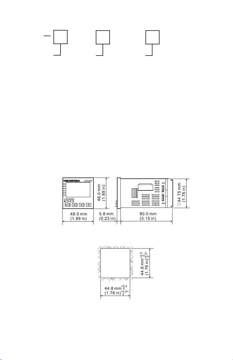
Select the position desired for the instrument on the panel. Prepare the panel by cutting
and deburring the required opening per the panel cut out dimensions listed below. Follow
the mounting instructions listed on page 4. Lastly, wire the controller per the appropriate
wiring diagram listed on page 5.
Physical Dimensions
Panel Cut Out
Page 3
Page 4
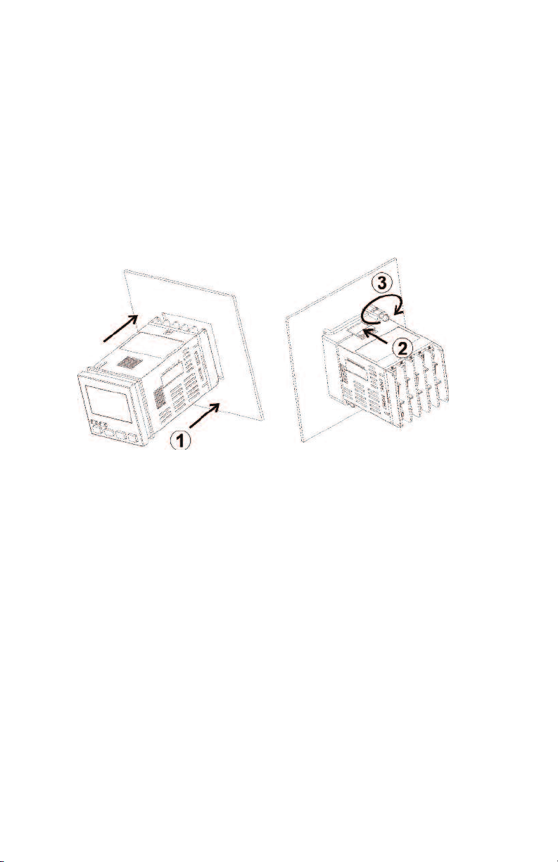
MOUNTING METHOD
Step 1: From the front of the panel, slide the controller housing through the cut out. The
housing gasket should be against the housing flange before installing.
Step 2: Slide the mounting collar over the housing from the rear of the panel.
Step 3: Push the mounting collar forward until the bracket stops at the panel wall.
Step 4: Insert and tighten the screws on the bracket to secure the controller in place.
(The screw torque should be 0.8 kgf-cm).
Mounting Bracket Installation
Page 4
Page 5
WIRING
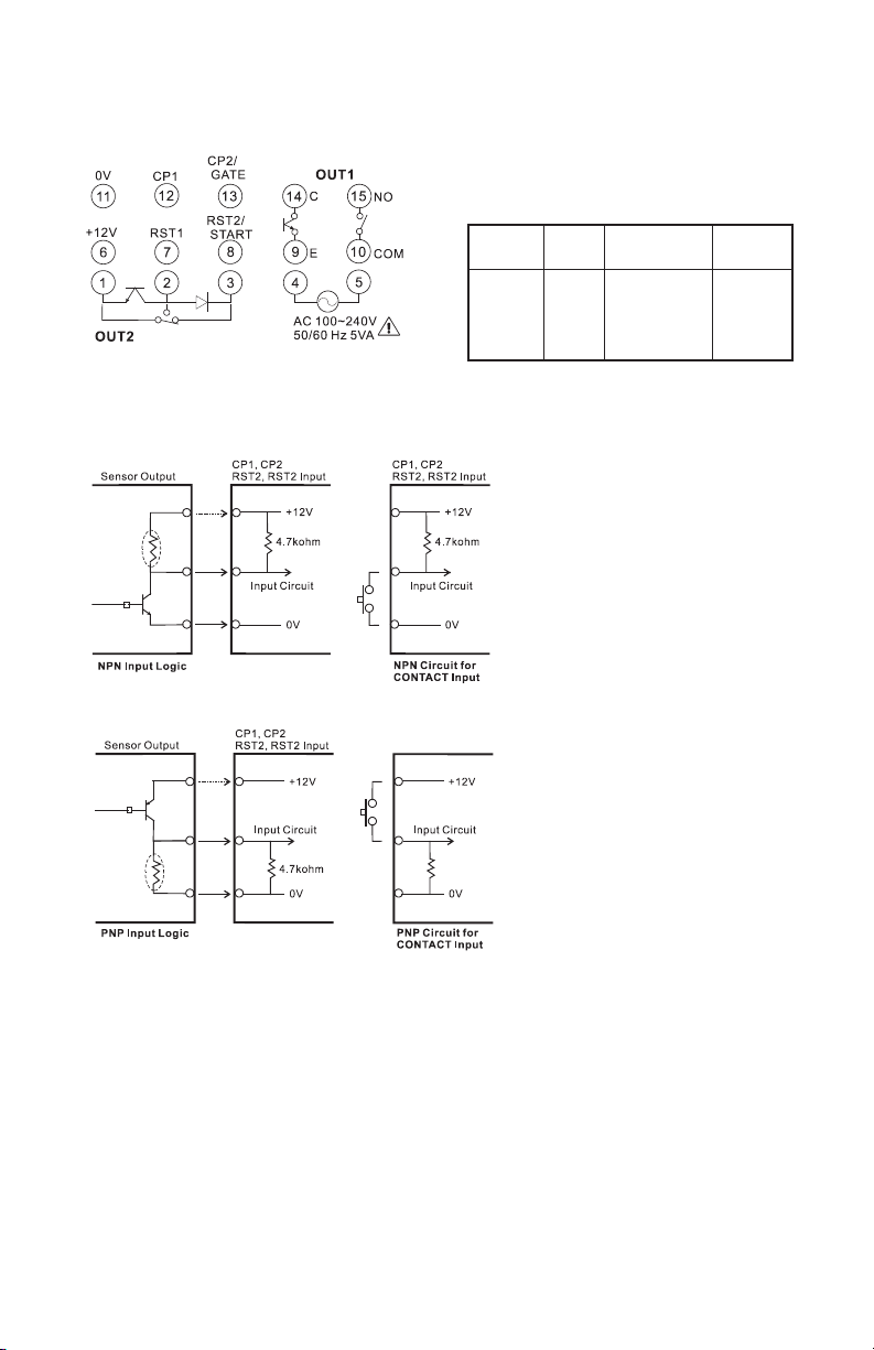
Terminal Identification
Input Connections
NPN
PNP
Multi-Function Input PIN
Counter
CP1
CP2
Reset1
Reset2
Timer
Gate
Reset1
Start
Tachometer
CP1
Reset1
Timer &
Counter
CP1
Gate
Reset1
Start
Page 5
Page 6
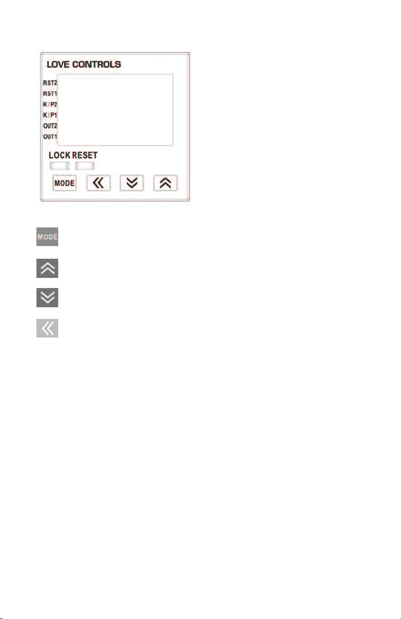
FRONT KEY FUNCTIONS
Key functions are as follows:
MODE: Pressing the Mode key advances the display to the next menu
item and saves any changed parameter values.
UP ARROW: Increments a value or changes a menu item. If pressed while
in the home display, the set point value will be increased.
DOWN ARROW: Decrements a value or changes a menu item. If
pressed while in the home display, the set point value will be decreased.
LEFT ARROW: Changes the selected digit to the left. This is used to
quickly change set point values for large values.
RESET: Clear and reset the PV display.
LOCK: Press to enter secure mode. See Security Feature section for
more information.
Page 6
Page 7

SECURITY FEATURES
The Series LCT216 has two built-in security lock settings to prevent unauthorized personnel
from changing parameter settings.
The LoC1 setting affects all parameters in the controller. If LoC1 setting is enabled, the
operator will have to unlock the controller to make any changes to the controller’s
parameters
The LoC2 setting affects all parameters except the set point and the reset function. If LoC2
setting is enabled, the only parameters that the operator will be able to change are the set
point and resetting the process value. In order to change any other parameters, the operator
will have to unlock the control before making a change.
In order to unlock the control, the operator must depress the MODE and LEFT ARROW key
simultaneously.
CONTROL OPERATION DESCRIPTION
Home Display
The HOME display is the normal display while the control is operating. If no errors or
functions are active, the HOME display will indicate the process value on the top display and
the set value on the bottom display. Below the set value, the current mode of operation will
be shown as TAC (tachometer), CNT (counter), or TMR (timer). There will also be a
descriptor for the time units and type of counter operation.
While in the HOME display, the user can use the UP ARROW, DOWN ARROW, and LEFT
ARROW keys to change the set point value. The RESET key will clear the process value.
The LOCK key will enable the security feature.
Parameter Configuration Display
Holding the MODE KEY for 3 seconds will enter the parameter configuration display. Once
in the parameter configuration display, the parameter will be listed in the top display and the
value of that parameter will be listed in the bottom display. Pressing the MODE key will cycle
through the parameters for the respective operation modes. The UP and DOWN arrows
change the values of the parameters. The MODE key must be pressed to save any changes.
Return to the HOME display by holding the MODE key for 3 seconds.
Page 7
Page 8

TIMER SETTINGS
The timer function of the series LCT216 takes a signal input to start a timing sequence. The
sequence can be paused using the GATE input or reset using RST1 input. Use the below
parameters and timing functions to configure the timer.
Parameter Configuration
PV SV
FUnC timE Sets the controller to function as a timer.
t mode UP Sets the display to count up or down.
down
t otmd Sets the output timing functions. See the timing functions
section or page 9 for detail description of each timing
function.
t Unit Sets the display units of measure. See below table for a
list of the available units.
Display
S 001
S 01
S 1
mS 001
mS 01
m 01
M 1
HmS
Hm 1
H 1
T oUt 1 Sets the pulse width (t) for output 1. The default output timeis
rtSr Sets the minimum pulse width at either 1 msec or 20 msec.
inPtLC Sets the transistor input type to NPN or PNP. For contact input,
Units
sec.
sec.
sec.
min., sec.
min., sec.
Min.
Min.
Hr., min., sec.
Hr., min.
Hr.
Range
0.01 to 9,999.99
0.1 to 99,999.9
1 to 999,999
0.01 to 9,959.99
0.1 to 99,959.99
0.1 to 99,999.9
1 to 999,999
1 to 995,959
1 to 999,959
1 to 999,999
Table A: List of Timing Units
0.02 seconds. If you wish the system to keep the operation of
the output, please set the output time to 0.00 seconds.
the selection can be either PNP or NPN, but the selection will
determine whether the connection is to terminal 11 or terminal 6.
See the input connection diagrams on page 5.
Resolution
10 msec.
0.1 sec.
1 sec.
10 msec.
0.1 sec.
0.1 min.
1 min.
1 sec.
1 min.
1 hr.
Maximum Time
9,999.99 sec.
99,999.9 sec
999,999 sec.
5,999.99 sec.
59,999.9 sec.
99,999.9 min.
999,999 min
359,999 sec. (100 hr.)
599,999 min. (10,000 hr.)
699,999 hr.
Page 8
Page 9

Timer Functions
Page 9
Page 10

COUNTER SETTINGS
Parameter configuration
PV SV
FUnC Cont Sets the controller to function as a counter
CntFUn Select the counter to perform single stage counting, two
stage counting, batch counting, total counting or dual
counting.
STAGE1 Controller has a single process value and set point value.
Output 2 will be the same as output 1.
STAGE2 Controller has up to two set point and process values. The
operation is based on the input modes and output types.
bAtCH Controller can be set to count batch processes. In this mode,
the counter will count up until it reaches the set value and then will
increment the batch present value by one. The process will
continue until the batch set point value is reached.
totAL Controller has a single set point. The display can show the
present value since last reset or total counts.
dUAL Controller will either add or subtract the counts from the two
counter inputs.
C inPt Counter input mode can be selected to count up or down when a
counter input signal is received.
UP The present value will increase with each counter input signal.
doun The present value will decrease with each counter input signal.
Page 10
Page 11

Ud A Command up / down setting will increase or decrease the
Co unti ng up
Cou nt ing d own
Prohibit
A A
0
1
2
3
4
H
L
H
L
0
CP1
CP2
Present
Val ue
CP1: Counter input CP2: Counter input prohibit ed
Note: has to be larger than width of min. Input signal
A
Prohibit
A A
0
1
2
3
4
5
H
L
H
L
0
CP1
CP2
Present
Val ue
CP1: Counter input prohibited CP2: Counter input
Note: has to be larger than width of min. Input signal
A
Prohibit
AA
n
n-2
n-1
n-4
n-3
H
L
CP1
CP2
Present
Val ue
0
H
L
CP1 : C ou nte r in put C P2 : Co un ter inp ut pro hib it ed
Note: has to be larger than width of min. Input signal
A
A
Prohib it
A
n
n-1
n-2
n-3
n-4
n-5
H
L
H
L
CP1
CP2
0
Present
Value
CP1 : C ou nte r in put pr oh ibi ted C P2: Cou nt er i np ut
No te: h as t o be la rge r t han wid th o f m in. In put sig na l
A
Co mm and co un tin g u p/ dow n
U
D_A
Indivi dual coun ting up/do wn
UD_B
Quadr ature inp ut
UD_C
B B B B
0
11
2
2
3
H
L
CP1
CP2
Present
Val ue
0
Note : has to be lar ger tha n width of 1/ 2 min. in put sign al.
B
H
L
0
present value with each counter 1 input signal depending on if
counter 2 input is engaged. When counter 2 input is engaged, each
counter 1 input signal will decrease the count.
Ud b Individual up / down setting will increase the present value with
each counter 1 input signal and decrease with each counter 2 input
signal.
Ud C Quadrature up / down uses the order of the inputs to determine
whether to count up or down. If counter input 1 leads counter input
2, the unit will count up. If counter input 2 leads counter input 1, the
unit will count down.
Page 11
Page 12

C otmd Counter Output Mode determines the output operation of the
control. It also determines how the counter will function after
reaching the set point. See the output mode charts on page 13 for
more information.
C SPEd Counting Speed can be set from one count per second up to
10,000 counts per second. This setting determines the minimum
input signal width.
t oUt1 Sets the pulse width (t) for output 1.
t oUt2 Sets the pulse width (t) for output 2.
Point Sets the number of digits to the right of the decimal point on the
display.
PSCALE Pre-Scale is used when converting the process value’s units of
measure. The pre-scale value would be set as the conversion factor.
(Pv = Pv * PSCALE)
PwErS Power Save feature allows the control to save the current process
value upon loss of power.
SAvE Save process value upon power loss
CLEAr Clear process value upon power loss
rtSr Minimum width of reset signal determines how long the reset
terminals must be engaged to reset the device.
inPtLC Input signal can be set for PNP or NPN. This parameter
determines which wiring diagram should be used.
Page 12
Page 13

Counter Output Mode Charts
RESET
999999
S
V1
SV2
0
OUT2
O
UT1
R
ESET
999999
SV2
SV1
0
OUT2
OUT1
RESET
999999
SV2
SV1
0
OUT2
OUT1
RESET
999999
S
V1
SV2
0
OUT2
O
UT1
Output
mode
setting
Inpu t mode
Up
Do wn Up/ Do wn A, B, C
K
P
Q
A
TT
TT
TTTTTT
TT TT
TT TT TTT TTT
TTTTTT
TT
T
T
TTT
TTT
999999
RESET
S
V2
SV1
OUT2
O
UT1
0
TT
T
T
TTT T
TT
R
ESET
9
99999
SV2
SV1
0
O
UT2
OUT1
TT
RESET
999999
S
V2
0
OUT2
OUT1
SV1
R
ESET
999999
SV2
SV1
0
OUT2
OUT1
TT TTT TTT
TT TT T
T
TTTT TT
TT T T TTT TTT
I
npu t mod e
U
p Do w n Up / Do w n A , B , C
F
N
C
R
Output
m
ode
s
etting
RESET
999999
SV2
SV1
0
OUT2
OUT1
RESET
99999 9
SV2
SV1
0
OUT2
OUT1
RESET
9
99999
SV1
SV2
0
OUT2
OUT1
O
utput
m
ode
setting
Inp ut mod e
Up/D own A , B, C
S
T
D
Output Modes S, T, and D can only be used with up/down counting inputs.
Page 13
Page 14

TACHOMETER SETTINGS
OUT 2 set val ue
Me asur eme nt va lue
OUT1 set value
OUT1
OUT2
OUT 1 set v alue : O UT1 ON
Meas ure ment va lue
OUT 2 set v alue : O UT2 ON
(LO-LO)
OUT2 set value
Mea sur eme nt va lue
OUT 1 se t valu e
OUT1
OUT2
Mea surem ent v alue
OUT 1 set va lue : O UT1 ON
Meas urem ent va lue OUT2 se t valu e : OUT2 ON
(LO-HI)
OUT2 set val ue
Measure ment value
OUT1 set va lue
OUT1
OUT2
(HI-LO)
Mea sur emen t valu e OU T1 set value : OUT1 ON
Mea sur emen t valu e
OUT2 set value : OUT2 ON
OUT 2 set val ue
Measurem ent value
OUT 1 set val ue
OUT1
OUT2
(HI-HI)
Measure ment value OU T1 se t valu e : OUT 1 ON
Measur ement value
OUT2 set value : OUT2 ON
Parameter Configuration
PV SV
FUnC tACH Sets the controller to function as a tachometer.
tAotmd Tachometer Output Mode determines the output condition when the
process value exceeds the set point value. See output mode charts
below for more information.
C SPEd Maximum Input Frequency can be set from one count per second up
to 10,000 counts per second.
Point Sets the number of digits to the right of the decimal point on the
display.
PSCALE Pre-Scale is used when converting the process value’s units of
measure. This value is commonly used to convert the input
frequency (counts per second) to a rotational speed (rpm) using the
below equation.
Frequency (Hz) * Pre-Scale = Rotation Speed (rpm)
Pre-Scale = 60 / n (where n = number of pulses per
revolution).
St tAC Initial Power Up Interrupt delays the output from triggering for up to
99.9 seconds.
St AvG Input Filter allows the tachometer to average 2, 4, or 8 readings to
give a more stable reading. (1= 2 data points, 2 = 4 data points, and
3 = 8 data points).
rtSr Minimum Width of Reset Signal determines how long the
inPtLC Input signal can be set for PNP or NPN. This parameter
Tachometer Output Mode Charts
reset terminals must be engaged to reset the device.
determines which wiring diagram should be used.
Page 14
Page 15

TIMER + COUNTER MIXED MODE SETTINGS
Parameter Configuration
PV SV
FUnC miX Sets the controller to function as a timer and counter.
T mode Timer Mode sets the timer to count up or Down.
T otmd Timer Output Mode sets the output timing functions. See the
timing functions section on page 9 for detail description of each
timing function.
t Unit Sets the display units of measure. See table A on page 8 for a list
of the available units.
C inPt Counter input mode can be selected to count up or down when a
counter input signal is received.
UP The present value will increase with each counter input
signal.
doun The present value will decrease with each counter input
signal.
C otmd Counter Output Mode determines the output operation of the
control. It also determines how the counter will function after
reaching the set point. See the output function tables on page 13
for more information.
C SPEd Counting Speed can be set from one count per second up to
10,000 counts per second. This setting determines the minimum
input signal width.
t oUt1 Sets the pulse width (t) for output 1.
t oUt2 Sets the pulse width (t) for output 2.
Point Sets the number of digits to the right of the decimal point on the
display.
PSCALE Pre-Scale is used when converting the process value’s units of
measure. The pre-scale value would be set as the conversion factor.
(Pv = Pv * PSCALE).
Page 15
Page 16

PuErS Power Save feature allows the control to save the current process
value upon loss of power.
SAvE Save process value upon power loss
CLEAr Clear process value upon power loss
rtSr Minimum width of reset signal determines how long the reset
terminals must be engaged to reset the device.
inPtLC Input signal can be set for PNP or NPN. This parameter
determines which wiring diagram should be used.
DIP SWITCH SETTINGS
The Series LCT216 can be configured either using the configuration parameters discussed
in the previous section or by using DIP switches located on the side of the housing. When
the DIP switch setting is turned on, the parameters can be viewed, but not changed using
the front panel.
SW
Counter
8
Reset Pulse Width
On = 1 ms, Off = 20 ms
7
Input Type
On = PNP, Off = NPN
6
N/A
5
Counting Speed
On = 10K CPS, Off = 30 CPS
4
Output Mode of Counter
See Table D
3
Output Mode of Counter
See Table D
2
Input Mode of Counter
On = Down, Off = Up
1
On = Enable DIP Switch
Off = Disable DIP Switch
Timer
Reset Pulse Width
On = 1 ms, Off = 20 ms
Units of Timer
See Table C
Units of Timer
See Table C
Units of Timer
See Table C
Output Mode of Timer
See Table D
Output Mode of Timer
See Table D
Time Counting Up/Down
On = Down, Off = Up
On = Enable DIP Switch
Off = Disable DIP Switch
Table B: DIP Switch Parameter List
Page 16
Tachometer
Reset Pulse Width
On = 1 ms, Off = 20 ms
Input Type
On = PNP, Off = NPN
N / A
Counting Speed
On = 10KHz, Off = 30 Hz
Output Mode of Tachometer
See Table D
Output Mode of Tachometer
See Table D
N / A
On = Enable DIP Switch
Off = Disable DIP Switch
Page 17

SW
SW5
OFF
ON
OFF
ON
OFF
ON
OFF
ON
SW3
OFF
ON
OFF
ON
SPECIFICATIONS
Operating Temperature Range: 32 to 122°F (0 to 50°C).
Humidity Conditions: 35 to 85% RH (non-condensing).
Control Output Ratings: (Out 1) Relay: SPST 5A at 250 VAC, Transistor: NPN Open
collector 100 mA / 30 VDC residual voltage = 1.5 VDC max; (Out 2) Relay: SPST 5A at
250 VAC, Transistor: NPN Open collector 100 mA / 30 VDC residual voltage = 1.5 VDC
max.
Weight: 4 oz (114 g).
Reset Time: 0.001 seconds minimum.
Inputs: Dry contact, PNP, or NPN.
Timing Functions: 14 pre-programmed timing functions.
Supply Voltage: 100 to 240 VAC 50 / 60 Hz.
Power Consumption: Less than 10 VA.
Internal Power Supply: 12 VDC ±10%, 100 mA..
Display: Two-line 6 digit negative transmissive LCD display.
Agency Approvals: CE, UL.
6
SW7
O
F
F
O
F
F
O
N
O
N
O
F
F
OF
F
ON
ON
Table C: Timer Units of Measure
SW4
OFF
OFF
ON
ON
Table D: Output Mode Configurations
Displayed Unit
OFF
0.01 s
OFF
0.1 s
OFF
1 s
OFF
min, 0.01 s
ON
min, 0.1 s
ON
0.1 min
ON
min
ON
hr, min, s
Output Mode Configuration
Counter
F
N
C
R
Timer
Signal ON Delay 1
Signal ON Delay 2
Signal OFF Delay
Signal ON
Tachometer
Lo-Lo
Lo-Hi
Hi-Lo
Hi-Hi
Page 17
Page 18

DANGER
. Make sure the power is disconnected when you check the unit inside.
2
1. When the power is on, DO NOT touch the AC terminals in case an electric shock
may occur.
WARNING
injury to workers or damages on other equipment when used in a dangerous environment, please make
sure it is installed in an automatic safety protection device.
LCT216 is an OPEN-TYPE device. They are intended for installation completely within
an overall panel and for use in counting or timing applications. If it will cause series
1. Always use recommended solder-less terminals: Fork terminals with isolation
(M3 screw, width 7.0 mm), hole (diameter 3.2 mm). Screw size: M3x6.5 (with
6.8x6.8 square washer). Recommended tightening torque: 0.4 N.m (4kgf.com).
Applicable wire: solid/twisted wire of 2 mm2, 12 AWG to 24 AWG. Please be
sure to tighten them properly.
2. Prevent dust or metallic debris from falling into the device and cause
malfunctions.
3. DO NOT modify or uninstall the device.
4. DO NOT use empty terminals.
5. Make sure the wires are correctly connected to proper terminals.
6. Keep away from high-voltage and high-frequency environment during
installation in case of interference.
7. Prevent using the device in premises which contain: dust or corrosive gas, high
humidity, high radiation, vibration and shock.
8. LCT216 is an open-type device. Make sure to install it in an enclosure to
prevent dust, humidity in case of an electric shock.
9. Please make sure the power cables and signal device are installed correctly
before switching on the power; otherwise serious damage may occur.
10. DO NOT touch the terminals or repair the device when the power is on;
otherwise an electric shock may occur.
11. Please wait for one minute after the power is switched off to allow the capacitor
to discharge and DO NOT touch the internal wiring within this period.
12. Use dry cloth to clean the device. DO NOT use acid or alkaline liquid to clean
the device.
©Copyright 2011 Dwyer Instruments, Inc Printed in U.S.A. 5/11 FR# R5-443702-00
LOVE CONTROLS DIVISION
DWYER INSTRUMENTS INC.
P.O. BOX 338 - MICHIGAN CITY, INDIANA 46361, U.S.A.
Phone: 219/879-8000 www.love-controls.com
Fax: 219/872-9057 e-mail:love@love-controls.com
 Loading...