

Page 1
SERIES IPFS
ADJUSTABLE DEPTH
INSERTION PADDLEWHEEL
INSTRUCTIONS
F-IPFS
IPFS-1XX
IPFS-0XX
Page 2

TABLE OF CONTENTS
General Information
General Information, Features, Specications .................................................................................................Page 1
Installation
Piping, Positioning the Meter, Immersion, Depth Setting ................................................................................ Page 2
IPFS-0 Installation, IPFS-1 Installation ............................................................................................................. Page 3
Dimension C, Pipe Wall Thickness .................................................................................................................... Page 4
Flow Rate ............................................................................................................................................................ Page 4
Straight Pipe Recommendations ......................................................................................................................
Full Pipe Recommendations ..............................................................................................................................Page 6
Connection
Calibration .......................................................................................................................................................... Page 7
Operation & Repair
Theory of Operation, Flow Range, Rotor Replacement ....................................................................................Page 8
Repair & Parts
Signal, Parts Explosion, Parts List .................................................................................................................... Page 9
Troubleshooting
Problem, Probable Cause, To Try.......................................................................................................................Back
TABLES AND DIAGRAMS
Features .............................................................................................................................................................. Page 1
Page 5
GENERAL INFORMATION
GENERAL INFORMATION
The IPFS Series are adjustable depth insertion paddlewheels
that come in brass or 316 stainless models to t 3” to 40” pipe.
Installation ttings are standard 1-1/2" or 2” NPT. Fittings such
as saddles and weldolets may be purchased either locally or from
Dwyer Instruments Inc.
Ruby bearings and a non-drag Hall-effect sensor give these meters
the widest ow range of any of the paddlewheel types. A sensor
detects the passage of miniature magnets in the six rotor blades.
The resulting square-wave signal can be sent for hundreds of
feet over unshielded cable without a transmitter and connected
directly to many PLC’s and other controls without any additional
electronics.
If desired, a modular system of electronics can be installed
FEATURES
IPFS-1XX
3/4” diameter tubing
for low insertion force
2” Adapter
removes to mount
hot-tap machine
Full-port 2” ball valve
for sensor removal
Adapter tting with
2” NPT threads
Locking collar
directly on the ow sensor or mounted remotely. The Series RTI
provides digital rate and total display, as well as programmable
pulse output; the Series RTI also provides a 4 to 20 mA analog
output. The Series BAT is a blind analog transmitter. Programmable pulse for pump pacing is available with the Series PWD.
The “hot-tap” models IPFS-1 can be installed or serviced without
shutting down the line by means of a 2” full-port isolation valve
that comes with a nipple for installation on the pipe tting. In most
circumstances, no special tool is required.
Modular electronics (optional)
• rate/total/pulse/4-20 mA
• blind 4-20 transmitter
• pulse divider
18 Foot Cable
Rugged cast aluminum housing
IPFS-0XX
Compression nut
for easy adjustment, secure locking
Adapter tting
with 1-1/2” male NPT threads
Specications Table ...........................................................................................................................................Page 1
Piping .................................................................................................................................................................. Page 2
Positioning the Meter ......................................................................................................................................... Page 2
Depth Setting ..................................................................................................................................................... Page 2
Meter Installation ............................................................................................................................................... Page 3
Table 1 (Dimension 'C') ...................................................................................................................................... Page 4
Table 2 (Pipe Wall Thickness) ............................................................................................................................ Page 4
Straight Pipe Recommendations ......................................................................................................................
Page 5
Full Pipe Recommendations ..............................................................................................................................Page 6
Connection Diagram .......................................................................................................................................... Page 7
K factor ................................................................................................................................................................ Page 7
Rotor Replacement ............................................................................................................................................Page 8
Parts Explosion ................................................................................................................................................... Page 9
Parts List ............................................................................................................................................................. Page 9
Troubleshooting: Problem, Probable Cause, To Try .......................................................................................... Back
SPECIFICATIONS*
Pipe Size
Sensor
Materials Housing
Sensor Body
Rotor
Shaft
Bearings
Isolation Valve
Fitting Size
Flow Range
Accuracy
Maximum Temperature
Maximum Pressure
Insertion Force
Power
Cable
*Specications subject to change.
Rotor housing
Removable jewel bearings for
exceptional low ow performance
Rotor
S-Size L-Size
3” to 12” (50 - 300mm) 12” to 40” (300 - 1000mm)
Hall Effect sensor, 12 Vdc current sinking pulse
Cast aluminum
Brass or 316 SS
PVDF
Nickel-bound tungsten carbide (zirconia ceramic optional)
Ruby jewel
IPFS-0 IPFS-1
None Bronze (316SS optional)
1.5” NPT 2” NPT
0.3 - 30 feet/sec (0.1 - 9 meter/sec)
+/- 1.5% of full scale
200˚ F (93˚ C)
200 psi (14 bar)
0.44 x pressure in pipe
5-24 Vdc, 1.5 mA
#22 AWG 3-con, 18’ (6m); 2,000’ (650m) maximum cable run
Page 1
Page 3
INSTALLATION
INSTALLATION
These ow sensors are not recommended
for installation downstream of the boiler
feedwater pump where installation fault
may expose the meter to boiler pressure
and temperature. Maximum recom-
mended temperature is 200˚ F.
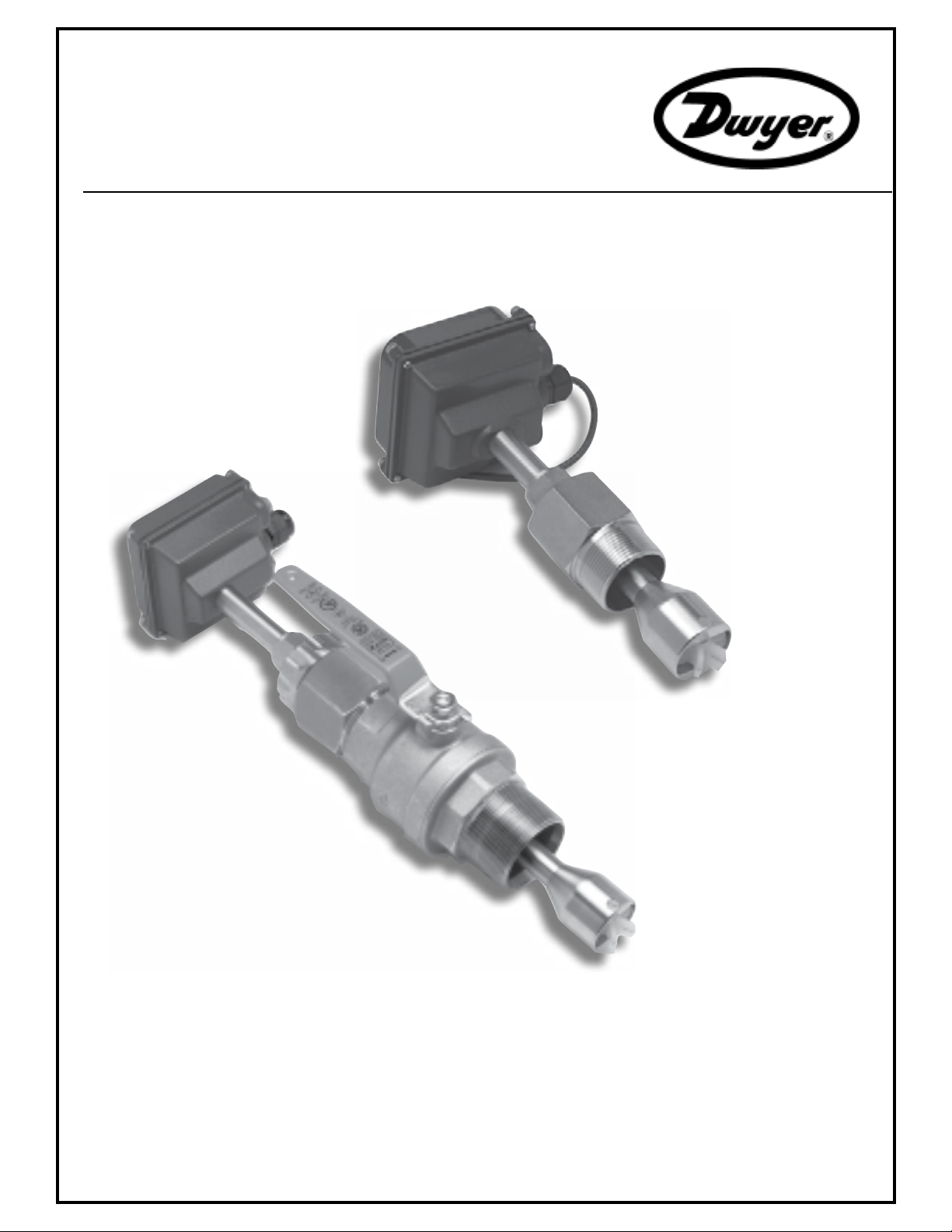
Piping. For best results, the IPFS sensor should be installed
with at least ten diameters of straight pipe upstream and ve
downstream. Certain extreme situations such as partially-
opened valves are particularly difcult and may require fteen
diameters upstream. (See Straight Pipe Recommendations.)
Horizontal is the preferred installation orientation, since it
improves low-ow performance slightly and avoids problems
with trapped air. Bottom, top, and vertical pipe installations
are all acceptable if required by the piping layout. (See Full
Pipe Recommendations.)
POSITIONING THE METER
Fair (unacceptable if
air is present)
Immersion. The IPFS Series standard sensors are not designed
for continuous underwater operation. If this is a possibility,
as in a ooded vault, a unit modied for immersion should be
specied (Option -IMM)
Depth Setting. It is important for accuracy that the sensor be
inserted to the correct depth into the pipe.
1. In Table 1 (on page 4), nd Dimension C for your sensor model
and pipe size.
2. Subtract wall thickness of your pipe (Table 2 on page 4) to
nd Dimension D.
3. Measuring from the outside of the pipe to the joint in
the housing, as shown in the diagram, adjust the sensor
to Dimension D and hand tighten compression nut.
4. Align the conduit housing with the centerline of the pipe,
as shown below. Be sure the arrow on the housing
points in the direction of ow.
strain relief
FLOW
5. Check Dimension D one more time.
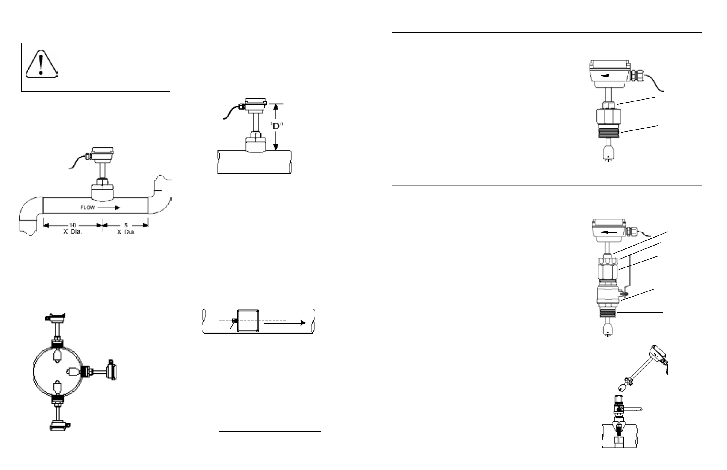
IPFS-0XX INSTALLATION
Fitting Installation. IPFS-0XX sensors come with a 1-1/2” male NPT pipe
thread adapter tting. Any tting that provides the matching NPT female
thread may be used. Installation procedure compensates for tting height
differences. Cut a minimum 1-3/4” hole in the pipe. If possible, measure
the wall thickness and write it down for use in depth setting. Then install
the threaded tting (saddle, weldolet, etc.) on the pipe.
Meter Installation. Loosen the compression nut so that the adapter
slides freely. Pull the meter fully upward and nger-tighten the compression nut. Using a thread sealant, install the adapter in the pipe tting. Do
not overtighten. Now loosen the compression nut, lower the meter to the
appropriate depth setting (see diagram and instructions, preceding page).
Caution: Do not allow the meter to fall into the pipe uncontrolled, as
this may damag the meter. Be sure ow is in the direction of the arrow
on the housing. Tighten compression nut fully.
IPFS-1XX INSTALLATION
‘Hot tap’ meters are designed to be installed and serviced without
depressurizing the pipe.
Fitting Installation. The hot tap sensors have a 2” NPT thread for
compatibility with the 2” isolation valve. Any tting that provides matching
NPT female thread may be used. The installation procedure compensates
for differences in tting height.
If initial installation is performed on an unpressurized pipe, cut a
minimum 1-3/4” hole in the pipe. If possible, measure the wall thickness
and write it down for use in depth setting. Then install the threaded tting
(saddle, weldolet, etc.) on the pipe.
If it is necessary to do the initial installation under pressure, any standard
hot tap drilling machine with 2” NPT adapter, such as a Transmate or a
Mueller, can be used. Ordinarily, it is not necessary to use an installation
tool, since the small-diameter tube can be controlled by hand but not
for higher pressures.
Compression nut
Adapter tting
with
standard NPT
threads
Compression nut
Locking collar
2” adapter removes
to mount hot-tap
machine
Full-port 2” ball
valve allows sensor
removal
Standard 2”
NPT threads
Page 2
Best
Fair (unacceptableifuid
containssediment)
6. Tighten the compression nut fully.
RECORD YOUR SETTINGS
Once you have the meter set up and operational, it is important to record your meter setttings and save them for
future reference.
K-Factor
Insertion Depth (Dim. D)
Meter Installation. Remove the sensor unit from the valve assembly.
Using a thread sealant, install the valve assembly on the pipe tting. If
the initial installation is a pressure (“hot”) tap, remove the 1-1/2” x 2”
adapter bushing at the back of the valve. Thread the tapping machine on,
open the valve, and tap using a minimum of 1-3/4” or maximum 1-7/8”
cutter. After retracting the machine and closing the valve, reinstall the
ow sensor. When the sensor is secure, open the valve and adjust depth
setting (see diagram and instructions, preceding page). Be sure ow is
in the direction of the arrow on the housing. Tighten locking collar and
compression nut fully.
IPFS-1XX Sensor
Removal
Page 3
Page 4

INSTALLATION
INSTALLATION
STRAIGHT PIPE RECOMMENDATIONS
Table 1: Dimension "C"
3" 4" 6" 8" 10" 12" 16" 24" 30" 36"
IPFS-0-S
IPFS-0-L
IPFS-1-S
IPFS-1-L
9.20 9.03 8.69 8.35 8.01 7.67 6.99 - - -
14.20 14.03 13.69 13.35 13.01 12.67 11.99 10.63 9.61 9.59
16.21 16.01 15.71 15.31 15.01 14.7 14.01 - - -
- 20.06 19.66 19.36 19.06 18.66 17.96 16.66 15.66 14.56
Table 2: Pipe Wall Thickness
Nominal Pipe Size
3" 4" 6" 8" 10" 12" 16" 24" 30" 36"
Nominal Pipe Size
(X = diameter)
Reduced Pipe
Two Elbows In Plane
Two Elbows, Out Of Plane
10X
20X
5X
IPFS
5X10X
IPFS
5X
PVC/Steel
Sch. 40
PVC/Steel
Sch. 80
Stainless
Steel (10S)
Stainless
Steel (40S)
Copper Tubing
(Type L)
Copper Tubing
(Type K)
Brass Pipe
Duct. Iron
(Class 52)
0.216 0.237 0.280 0.322 0.365 0.406 0.500 0.687 - -
0.300 0.337 0.432 0.500 0.593 0.687 0.843 1.218 - -
0.120 0.120 0.134 0.148 0.165 0.180 - - - -
0.216 0.237 0.280 0.322 0.365 0.375 0.375 0.375 0.375 -
0.090 0.100 0.140 0.200 0.250 0.280 - - - -
0.109 0.134 0.192 0.271 0.338 0.405 - - - -
0.219 0.250 0.250 0.313 0.365 0.375 - - - -
0.280 0.290 0.310 0.330 0.350 0.370 0.400 0.440 0.470 0.530
Expanded Pipe
Spiral Flow
Propeller Meter
20X
IPFS
5X
IPFS
30X
IPFS
50X
Page 4
Swirling Flow
Partially Open
Buttery Valve
IPFS
Page 5
Page 5

INSTALLATION
CONNECTION
FULL PIPE RECOMMENDATIONS
Allows air pockets to form at sensor
CONNECTION
RECOMMENDEDNOT RECOMMENDED
Ensures full pipe
RECOMMENDEDNOT RECOMMENDED
Sensors are supplied with 18 ft. of cable. For sensors with
no additional electronics, see diagram for color coding of
connections. For sensors with on-board electronics, see the
manual accompanying the electronic module.
5 to 24VDC
Table 3: IPFS K-factors
3" 4" 6" 8" 10" 12" 16" 24" 30" 36"
Nominal Pipe Size
Calibration (“K-Factor”). In order to properly process pulses from
the ow sensor, a number must be entered into the control to
which the sensor is connected. This number, called the K-factor,
is the number of pulses the sensor puts out per unit of uid
passing through the pipe. It is normally provided for Seametrics
sensors in pulses per gallon, and is given on the chart “K-factors
for Various Pipe Sizes.” These numbers are based on extensive
testing, which has shown close agreement between different IP
sensors in the same installation. Typically, most K-factor error
can be attributed to installation variables, such as depth setting
and tting conguration.
It is occasionally possible to eld calibrate a sensor by catching
the uid in a measured container and comparing with the number
of pulses recorded. (To record individual pulses, set the K-factor
on the control to 1.00.) This is especially desirable if the installation has less than the recommended length of straight pipe
upstream of the sensor.
Post-valve cavitation can create air pocket Keeps pipe full at sensor
RECOMMENDEDNOT RECOMMENDED
Air can be trapped
Allows air to bleed off
Caution: These ow sensors are not recommended for installation down-
stream of the boiler feedwater pump where installation fault may expose the
ow sensor to boiler pressure and temperature. Maximum recommended
temperature is 200°F.
PVC/Steel
Sch. 40
PVC/Steel
Sch. 80
Stainless Steel
(10S)
Stainless Steel
(40S)
Copper Tubing
(Type K)
Copper Tubing
(Type L)
Brass Pipe
Duct. Iron
(Class 52)
34.246 19.221 7.830 4.611 2.883 1.859 1.224 .577 - -
38.329 21.844 8.779 4.980 3.213 2.097 1.304 .656 - -
30.331 16.581 7.045 4.270 2.621 1.703 1.160 .519 .332 -
34.246 19.221 7.830 4.611 2.883 1.836 - - - -
38.145 21.420 8.846 5.027 3.302 2.126 - - - -
37.167 20.774 8.505 4.873 3.167 2.011 - - - -
34.381 19.545 7.658 4.593 2.883 1.836 - - - -
28.137 16.994 7.238 4.213 2.633 1.681 1.065 .461 .297 .207
Page 6
Page 7
Page 6

OPERATION & REPAIR
REPAIR & PARTS
OPERATION
Theory. In principle, an insertion ow sensor measures the
velocity of ow at one point in the pipe, and ow rate and total
can be inferred from this one point. Accuracy is decreased
by any factor which makes the ow at the measured point
unrepresentative of the entire ow stream. This includes
distorted ow patterns caused by upstream ttings too close
to the sensor. The worst offenders are ttings that increase
the ow on one side of the pipe, such as partially-opened
gate or buttery valves. Fluid moving in a pipe does not all
ow at the same velocity. Toward the center of the pipe,
uid moves faster than at the wall, and the relationship between the two changes as overall ow rate increases. This
change in the “velocity prole” can result in non-linearity,
which means that the K-factor that is correct for one ow
rate may be incorrect for another. The recommended depth
settings have been carefully chosen to minimize this source
of error, and should be followed carefully, especially in the
smaller pipe sizes.
Flow Range. These sensors are designed to operate at ow
velocities of 0.3 to 30 feet per second. If erratic readings
are encountered at low ows, check the chart to see if ow
is below minimum for the pipe size. The standard shaft and
bearings should have a long life at continuous high ow.
WARRANTY/RETURN
Refer to "Terms and Conditions of Sale" in our catalog or on
our website. Contact customer service to receive a Returns
Goods Authorization number before shipping your product
back for repair. Be sure to include a brief description of the
problem plus any relevant applciation notes.
REPAIR
Caution! Never attempt to remove a ow
sensor when there is pressure in the pipe
unless it is specically designed for hot
tap installation and removal. Loosen the
compression nut slowly to release any trapped pres-
sure. If uid sprays out when removing the sensor,
stop turning and depressurize the pipe. Failure to
do so could result in the sensor being thrown from
the pipe, resulting in damage or serious injury.
Rotor Replacement. Rotors are easily eld-replaced. Shaft
and rotor are a single unit, and are not replaced separately.
If replacement is due only to normal shaft wear, bearing replacement is probably not necessary. If the rotor has been
damaged by impact, the bearings should also be replaced.
Rotor and bearings can be ordered as a kit. Follow these
steps:
1. Unscrew the threaded bearing housings to expose
the shaft ends. If bearings are being replaced,
back them completely out.
2. Remove the rotor. Put the new rotor in its place.
3. Thread in one bearing housing part way, then the
other. Take care to start the end of the shaft into
the bearing hole before tightening further.
4. Screw in bearing housings until they bottom.
Note: Do not use excessive force.
5. Check for free spin. Blowing lightly on the rotor
should result in it spinning rapidly and coasting to
a smooth stop.
.
Signal
The ow sensor has only one moving part, the rotor. If this is
turning properly and there is no signal, the Hall-effect sensor is
not operating properly. To check the signal, apply 12 Vdc regulated* power to the red (+) and black (-) leads. Set a multimeter
to voltage reading. Put the positive multimeter lead on the red
wire and the negative lead on the white wire. Slowly turn the
rotor. Voltage reading should swing between +12 Volts and 0
Volts as the rotor turns. If it does not, the Hall effect sensor
is not working properly. Checking for continuity is not a useful
test of these sensors.
*NOTE: An unregulated power supply can exceed max voltage of micro
powered sensor (gray cable) and damage sensor.
Parts Explosion
IPFS-0XX Parts
1 Upper housing assembly
2 Gasket
3 Lower housing
4 Housing screw (4 req'd)
5 Plug, steel
6 Plug, plastic
7 Strain relief
8 Pickup, Standard (for RTI)
9 Tube
10 Compression nut
11 Compression ferrule
12 Adapter tting
13 Rotor housing O-ring (EPDM)
14 Rotor housing
15 Jewel bearings (2 req)
16 Rotor with shaft
Rotor repair kit
17
(includes of #15 & #16)
Page 8
IPFS-1XX (HOT-TAP) Parts (not shown)
Adapter tting
Ball valve assembly
Collar, locking
Hex nipple, 2"
Page 9
Page 7

TROUBLESHOOTING
Problem
No pulse output
Output pulses incorrect
Jumpy reading
Probable Cause Try...
Below minimum ow cutoff
Empty pipe
No power
Incorrect depth setting
Pipe not full
Not enough straight pipe
Fluctuating ow rate
Fluctuating around low ow cutoff
Not enough straight pipe
Check Table for velocity vs. pipe size
Check plumbing
Check connections
Check depth setting from Dimension “C” table
Refer to Installation/diagrams
Refer to Installation/diagrams
Refer to installation diagrams
Check Table for velocity vs. pipe size
Refer to Installation/diagrams
Dwyer Instruments, Inc. • 102 Indiana Highway 212 • Michigan City, IN 46360 • USA
(P) 219.879.8868 • (F) 219.872.9057 • 1.800.872.9141 • www.dwyer-inst.com
PL-OM-65200389-090512
9/5/2012
 Loading...