

Page 1
Series HFO Flow Alarm
Specifications – Operating Instructions
Bulletin F-HFO
Series HFO Flow Alarms are typically used to
make or break a set of electrical contacts to
signal a limit setting. They may be used to turn
on a warning light, sound a bell or horn, or even
to shut down a process. The switches on the
flow alarm can be configured to open or close a
contact for an increasing or decreasing set
point. Decreasing flow set points may be
located anywhere in the lower 2/3 of the scale
while increasing set points may be located
anywhere in the upper 2/3 of the scale.
Note: Refer to Series HF In-Line Flow Monitor,
Bulletin F-55, “Installation and Operating
Instructions” for installation, operation, and
cleaning instructions for the basic flow monitor
cartridge (included). The following instructions
are specifically for the Series HFO Flow Alarm
switches.
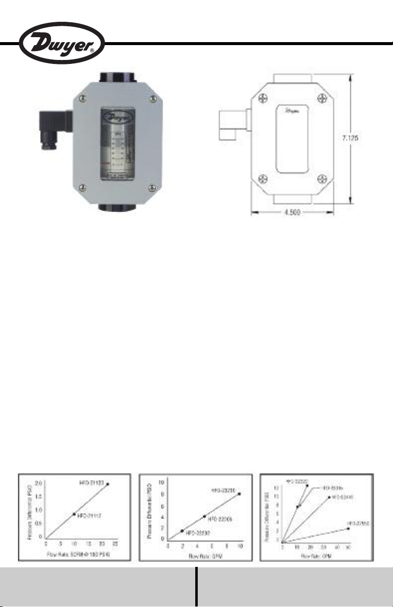
PRESSURE DIFFERENTIAL VS. FLOW RATE
1/4˝ FEMALE NPT 1/2˝ FEMALE NPT 3/4˝, 1˝ & 1-1/2˝ FEMALE NPT
SPECIFICATIONS
Service: Compatible gases or liquids.
Wetted Materials: Body: Aluminum, brass or
304 SS; Seals: Buna-N or Fluoroelastomer;
Magnet: PTFE coated Alnico; Other internal
parts: 304 SS.
Viscosity Limit: 500 SSU.
Temperature Limits: 170°F (76°C).
Pressure Limits: See Chart.
Enclosure Rating: NEMA 4X (IP65).
Accuracy: Measuring ±4% FS over entire
range; ±2.5% over center third of the
measuring range.
Repeatability: ±1% of full scale.
Switch Type: SPDT, 10A @ 250 VAC; 0.5A @
125 VDC (resistive), 1/4 hp @ 250 VAC
(inductive); 3A @ 125 VAC “L” lamp load.
Shipping Weight: 1/4 to 1/2˝ female NPT
Models: 3 lb (1.4 kg); 3/4 to 1˝ female NPT
Models: 4.5 lb (2.0 kg); 1-1/2˝ female NPT
Models: 12 lb (5.4 kg).
DWYER INSTRUMENTS, INC.
P.O. BOX 373 • MICHIGAN CITY, INDIANA 46360, U.S.A. Fax: 219/872-9057 e-mail: info@dwyer-inst.com
Phone: 219/879-8000 www.dwyer-inst.com
Page 2
Operation:
44 44
2
222
6666
88
1
100
88
1
100
GGPPMM
P
OINTER
S
S WWIITTCC HH GG LL II DDEE
SS CC RR EE WW
FF LL OO WW RR AA TT EE
SS CC AA LL EE
AA LL AARRMM
S
S WWIITTCC HH
FF LL OO WW IINNDDIICC AA TT OORR
L
L IINN EE
F
F OO LL LLOO WWEERR
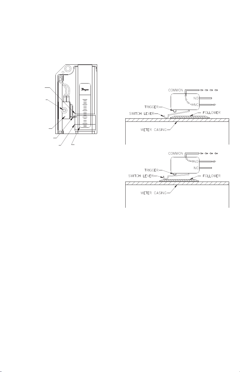
Illustration 1 shows the primary mechanism for
a single flow alarm. The HFO dual-switch flow
alarms contain two sets of these same
components (wiring to the DIN connector is
described on page 3). The configuration is such
that the high alarm is for increasing flow, and the
low alarm is for decreasing flow.
Illustration 1
The follower moves in unison with an orifice
plate inside of the unit’s pressure vessel via a
magnetic coupling in order to indicate flow rate.
As the follower moves with changes in flow rate,
the flow rate is determined by relating the
position of the flow indicator line to the
increments on the flow rate scale.
The pointer indicates the set point for the alarm
switch. In Illustration 1, the switch will be
actuated at all flow rates below 4 GPM. To
change the set point, simply loosen the switch
glide screw one (1) turn and slide the switch to
the desired position along the flow rate scale.
When the pointer is pointing to the desired flow
rate, re-tighten the switch glide screw.
Switches:
The switch is a simulated roller, lever operated
low force microswitch. The specifications for this
switch are listed on the first page. The switch is
actuated when movement of the follower
causes the switch lever to be lifted. In Illustration
2, the switch has not yet been actuated, and the
electrical circuit is through the normally closed
(NC) contact. Illustration 3 shows the switch
after it has been actuated. In this scenario, the
electrical circuit is through the normally open
(NO) contact.
Illustration 2
Illustration 3
Page 3

Precautions:
• Be certain to properly ground the unit via the
ground (G) pin located on the unit’s DIN
connector.
• In order to avoid accidentally removing the
switch glide screw, never loosen it by more than
one or two turns. This screw can be difficult to
replace if accidentally removed.
• Avoid over tightening the switch glide screw.
• When the switch adjustments are complete,
make certain that the wires that are attached to
the switch have not been moved into a location
that will interfere with the follower or the switch
lever.
• Do not make any modifications to the unit’s
internal wiring.
Electrical Connections:
Standard Flow Alarms are pre-wired with 4-pin
DIN connectors which consist of a male section
as shown in Illustration 4 and the female section
shown in Illustration 5. To open the female
section, first remove the screw, then lift the
connector portion out of the casing by inserting
the head of a screwdriver into the
slot marked for that purpose. Illustration 6
shows the disassembled female section.
Illustration 4
Illustration 5
Illustration 7 shows the connections for the low
alarm switch as the unit is shipped from the
factory. The wiring code below identifies how
the DIN connector is configured for dual alarms.
If the NC contacts are needed for either switch,
a simple adjustment must be performed. On the
switch itself, disconnect the NO lead from the
quick connect terminal, and place it onto the NC
contact. This will change the operating condition
of that particular alarm switch.
Illustration 7, Low Alarm
Wiring Code: Dual Switch Alarm
White Both Common Terminal #1 of DIN
Black Decreasing N.O. Terminal #2 of DIN
Contact
Red Increasing N.O. Terminal #3 of DIN
Contact
Green Enclosure Ground Terminal “G” of DIN
Illustration 6
Page 4

STANDARD CONTROL CIRCUITS
©Copyright 2012 Dwyer Instruments, Inc. Printed in U.S.A. 5/12 FR# R1-443344-00 Rev. 4
DWYER INSTRUMENTS, INC.
P.O. BOX 373 • MICHIGAN CITY, INDIANA 46360, U.S.A. Fax: 219/872-9057 e-mail: info@dwyer-inst.com
Phone: 219/879-8000 www.dwyer-inst.com
 Loading...