

Page 1
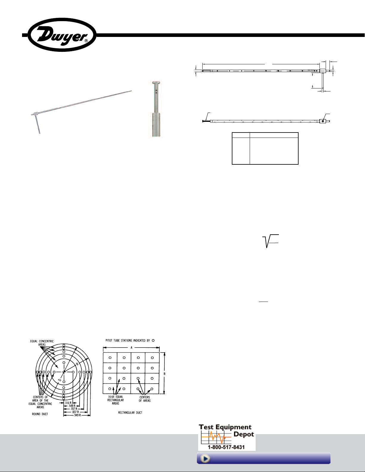
Series 160F Straight Pitot Tubes
A
5/8
[16.00]
2-35/64
[64.54]
1/4
[6.30]
5/16
[7.92]
Ø1/8
[Ø3.05]
1/4
[6.35]
[4] Ø 3/64 [Ø1.09] PRESSURE HOLES
[2 ON EACH SIDE]
Installation and Operating Instructions
Bulletin AQ-160F
Series 160F Pitot Tubes are designed to meet the need of the environmental
testing field for an inexpensive, yet accurate and reliable way to measure the flow
of air or gas streams.
For maximum accuracy of ±2%, as in laboratory applications, care is required and
the following recommendations should be followed.
1. Duct diameter should be 4˝ or larger.
2. Point total pressure opening upstream facing flow, and static
pressure opening downstream pointing in the direction of the flow.
The faces of both openings must be perpendicular to the airflow.
3. Make an accurate traverse per drawings; calculate the velocities at
each point and average them.
4. Take readings in a smooth, straight duct section a minimum of 10-15
duct diameters in length upstream and 5 diameters downstream
from the pitot tube.
5. Provide an egg-crate type straightener upstream from the pitot tube
for best performance.
TAKING AIR VELOCITY READINGS
To measure air velocity with a Series 160F Pitot Tube, make a 0.35˝ opening in
duct. Connect tubing from total pressure port or port facing flow to high pressure
side of manometer, and from static pressure port or port facing perpendicular to
flow to the low pressure side. If reading is negative, reverse connections.
Make a series of readings traversing the duct in horizontal and vertical planes.
Using velocity pressures recorded at each location, calculate velocities and
average them for final velocity value. See Figure 1 for more detail.
Model
160F
160F-24
160F-36
160F-48
160F-60
SPECIFICATIONS
Wetted Material: 304 SS.
Accuracy: ±2% FS, 0 to 9000 FPM (45 M/s).
K-Factor: 0.81.
Temperature Limit: 1500°F (815°C).
Process Connections: 1/4˝ OD.
Weight: 4.3 oz (122 g).
CALCULATING VELOCITY
Air Velocity = 1096.2 (Cp) P
where:
Pv = Sensed pressure difference (velocity pressure) in inches of
water column
D = Air density in lbs./ft.3(dry air = .075)
Cp = Pitot tube coefficient: 0.81
Air Density = 1.325 X P
PB= Barometric pressure in inches of mercury
T = Absolute Temperature (Indicated Temperature in °F plus 460)
Flow in cubic feet per minute equals duct cross sectional area in square feet x air
velocity in feet per minute.
Dimension “A” in (mm)
19-9/32 (489.56)
25-9/32 (642.14)
37-9/32 (946.94)
49-9/32 (1251.74)
61-9/32 (1556.54)
v
D
B
T
Traverse on Round and Square Duct Areas
Figure 1
DWYER INSTRUMENTS, INC.
With dry air at 29.9 inches of mercury, air velocity can be read directly from
temperature correction charts on reverse.
99 Washington Street
Melrose, MA 02176
Phone 781-665-1400
Toll Free 1-800-517-8431
Visit us at www.TestEquipmentDepot.com
Page 2
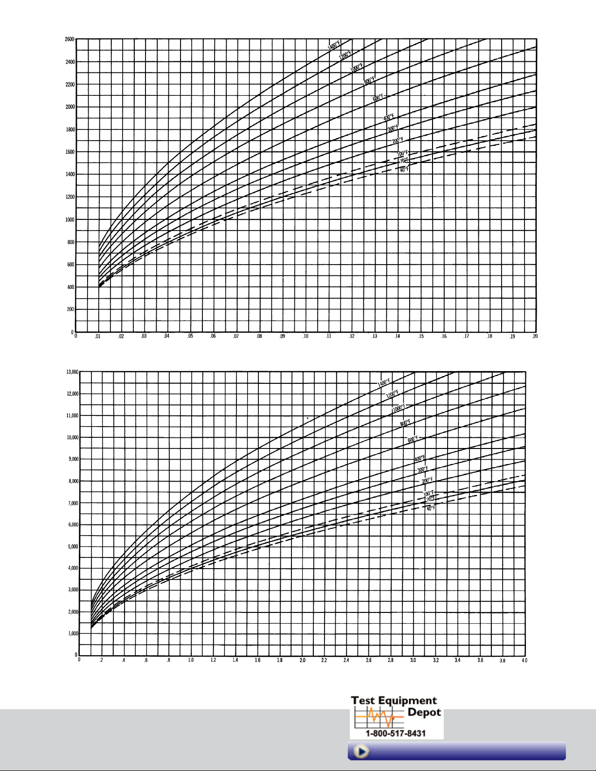
AIR VELOCITY IN FEET PER MINUTE
GAGE READING WITH 160F PITOT TUBE (VELOCITY PRESSURE) IN INCHES OF WATER
AIR VELOCITY IN FEET PER MINUTE
GAGE READING WITH 160F PITOT TUBE (VELOCITY PRESSURE) IN INCHES OF WATER
©Copyright 2015 Dwyer Instruments, Inc.
Printed in U.S.A. 3/15
DWYER INSTRUMENTS, INC.
FR# 443939-00 Rev. 2
99 Washington Street
Melrose, MA 02176
Phone 781-665-1400
Toll Free 1-800-517-8431
Visit us at www.TestEquipmentDepot.com
 Loading...