

Page 1
Bulletin A-34-DSGT
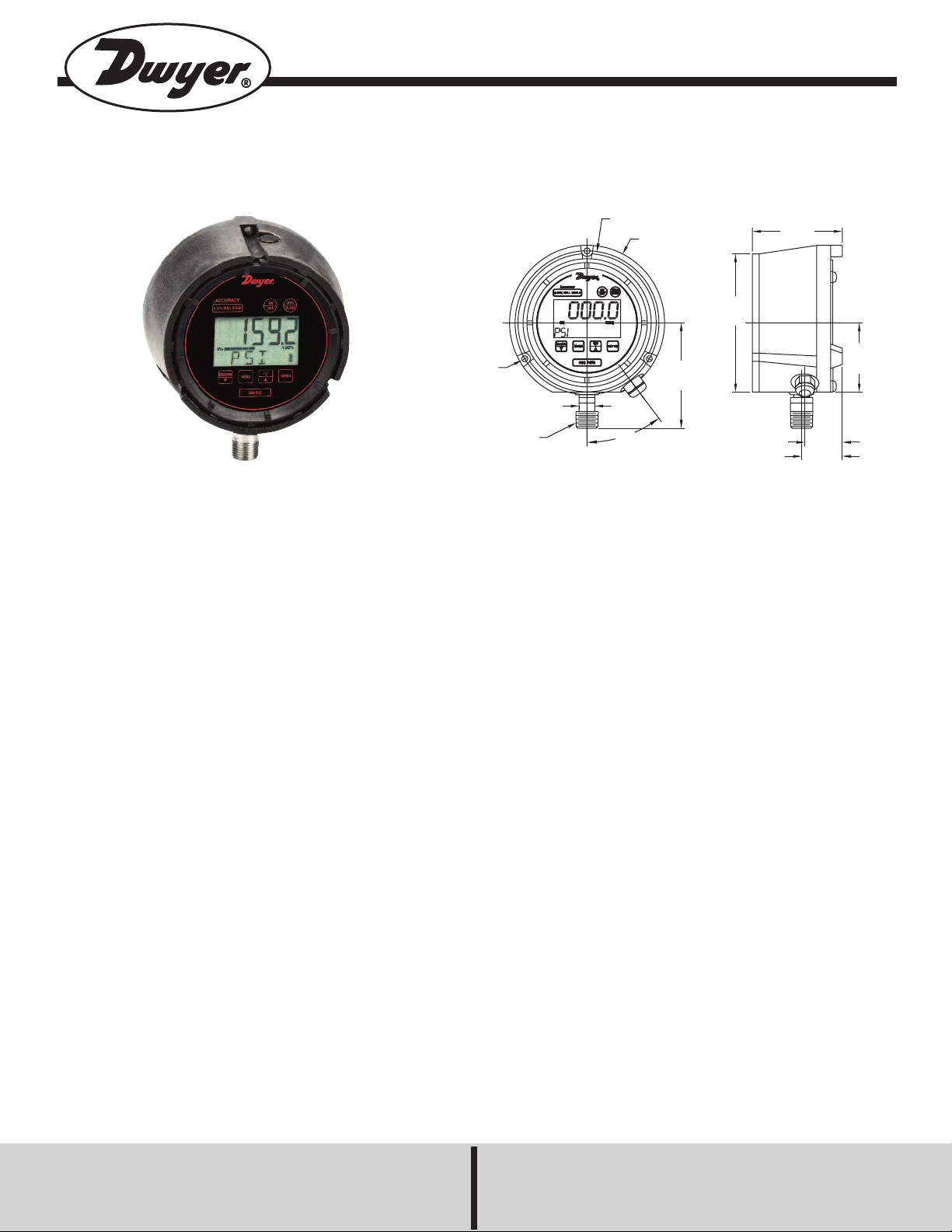
Ø5-3/8 B.C.
[Ø136.4]
Ø
5-13/16
[
Ø147.6]
3
-29/32
[
99]
37
1/2 NPT
5/8˝ [15.8] ACROSS FLATS
(3) Ø1/4 [Ø6.3]
3-5/16
[83.8]
Ø5-3/16
[Ø131.8]
1
-1/2
[
38.1]
1-13/32
[35.6]
2
-19/32
[
66]
Series DSGT Digital Indicating Transmitter
Specifications - Installation and Operating Instructions
The Series DSGT Digital Indicating Transmitter is a versatile multi-
function process gage that features an excellent 0.25% F.S. accuracy.
This all-in-one digital gage package is designed to reduce installation
costs, instrument cost, and save space where an application requires a
gage, transmitter, and switches. The gage comes standard with a looppowered 4-20 mA transmitter output and is offered with one or two
optional SPDT switches.
The DSGT gage is housed in a durable fiberglass reinforced thermoplastic case that is designed to meet NEMA 4 (IP65) requirements. The
gage features a menu-driven display for easy customization. User selectable features include 12 engineering units of measure, password protected calibration and disable functions, as well as an adjustable bar
graph and update/dampening rates.
INSTALLATION
When installing the gage, use a 5/8˝ wrench on the wrench flat of the
gage to tighten the gage to the process. DO NOT tighten the connection by applying torque to the gage body which could cause permanent
damage and render the gage inoperable. It is good practice to apply
pipe thread sealant tape or pipe thread sealant to the gage threads.
SPECIFICATIONS
Gage Specifications
Service: Compatible, non-combustible liquids & gases.
Wetted Materials: 17-4 SS sensor, 316 SS socket.
Housing Materials: Fiberglass reinforced thermoplastic case.
Accuracy: 0.25% F.S (Includes linearity, hysteresis, and repeatability).
Pressure Limit: 2 x F.S. range.
Process Connection: 1/2˝ male NPT.
Enclosure Rating: NEMA 4 (IP65).
Display: 5 Digit (0.88˝ high), 50,000 counts.
Transmitter Specifications
Accuracy: 0.25% F.S. (Includes linearity, hysteresis, and repeatability).
Temperature Limits: 14 to 140ºF (-10 to 60ºC).
Thermal Effects: 0.04% F.S./ºF.
Power Supply: 12-36 VDC (Loop Powered).
Output Signal: 4-20 mA.
Zero and Span: Menu Configurable.
Response Time: 100 ms.
Electrical Connections: 3 ft flying leads.
Loop Resistance: DC; 0-1090 ohms maximum.
Switch Specifications
Switch Type: 1 SPDT (-C1S option); 2 SPDT (-C2S option).
Repeatability: 0.25% F.S.
Electrical Rating: 1A @ 24 VDC or 0.5A @ 125 VAC.
Electrical Connections: 3 ft flying leads (See Wiring for details).
Power Requirements: 12-36 VDC (Separate line power).
Set Point Adjustments: Adjustable through menu selections.
Phone: 219/879-8000 www.dwyer-inst.com
DWYER INSTRUMENTS, INC.
P.O. Box 373 • Michigan City, IN 4636 U.S.A. Fax: 219/872-9057 e-mail: info@dwyermail.com
Page 2
DSGT KEYPAD OPERATION
ON
OFF
Z
ERO
CLEAR
MAX/MIN
M
MENU
E
ENTER
This button turns the gage on and off. When pressing the ON/OFF key while in the off position, the gage display will first indicate the
software version followed by the full-scale pressure range. The gage will then display the indicated pressure and be ready for use.
After power up and before the pressure is applied, this button will re-zero the gage from any initial zero shift. If the zero shift is greater
than programmed zero allowance, the gage display will show OFSET (blinking) for 1 second and then return to the measure mode.
The gage will auto advance once zeroed.
In the MAX/MIN mode the ZERO/CLEAR key will erase the stored minimum and maximum pressure values. To clear these values
press the ZERO/CLEAR key while the minimum or maximum value is being displayed.
The MAX/MIN button allows review of the minimum and maximum pressure values that have been measured since unit start-up or
since the values were last cleared. From the measurement mode, press the MAX/MIN key to:
1.) Indicate the maximum pressure
2.) Indicate the minimum pressure
3.) Exit Max/Min mode and return the gage to measurement mode.
The t (down arrow key) is used in the Menu mode. See the following MENU key section.
The MENU key allows for customization of the gage. Pressing the MENU key allows cycling through the main MENU items: UNITS,
CONFIG, GRAPH, OFF, and UPDAT & DAMP. Any item changed in the menu is saved as the new default setting(s) in the event of a
power loss.
The s (up arrow key) and t (down arrow key) allow for scrolling through the MENU options to increase or decrease numeric values as
required. While in the menu mode, the gage will automatically advance to the measurement mode once the selected MENU item has
been set.
This key manually turns the backlite on or off. There are five options available which include NEVER, 10 sec., 30 sec., 1 min., and 5
min. With the NEVER option selected the backlight will remain on while the gage is on or until this key is pushed again. The 10 sec.,
30 sec., 1 min., and 5 min. options allow the backlight to automatically turn-off after the selected period of time.
To use the BACKLITE option:
Step 1: Press the MENU key.
Step 2: Press the s (up arrow key) or t (down arrow key)
until the word LITE appears.
Step 3: Press ENTER.
Step 4: Press the s (up arrow key) or t (down arrow key)
to select the BACKLITE option.
Step 5: Press the ENTER key to finalize your choice of
LITE options.
This key allows for selecting gage features in the menu and sub-menus as well as finalizing the selections made. Use of the ENTER
key is described throughout this installation and operation manual.
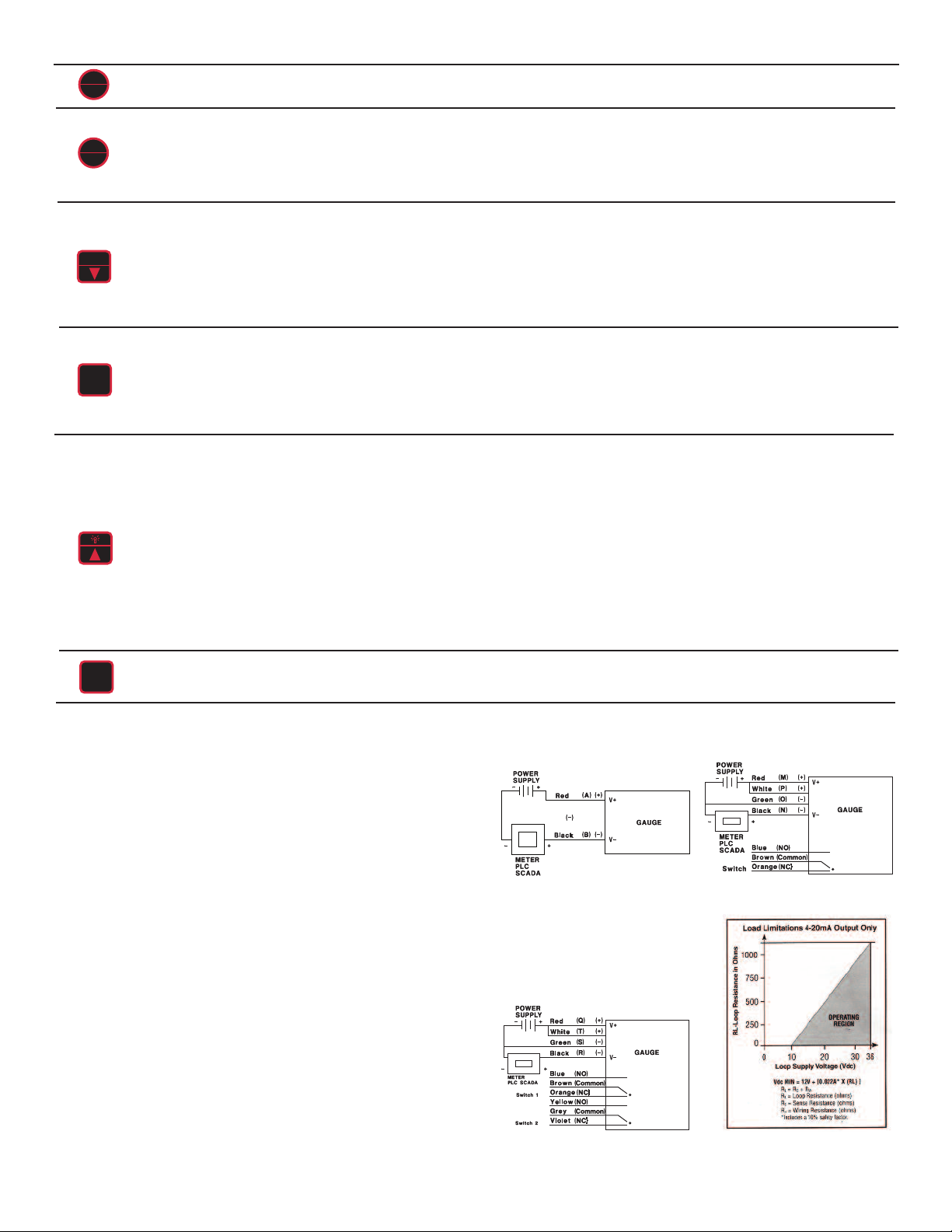
ELECTRICAL CONNECTIONS
CAUTION: DO NOT EXCEED SPECIFIED SUPPLY VOLTAGE RAT-
INGS. PERMANENT DAMAGE NOT COVERED BY WARRANTY WILL
RESULT. THIS UNIT IS NOT DESIGNED FOR 120 OR 240 VOLT AC
LINE OPERATION.
Electrical connections to the Series DSGT Indicating Transmitter are
made with the 3 foot flying lead cable. Refer to Figure A for wiring
Models DSGT-XXX-C0S, Figure B for Models DSGT-XXX-C1S, and
Figure C for Models DSGT-XXX-C2S.
Wire Length – The maximum length of wire connecting the transmitter
output and receiver is a function of wire size and receiver resistance to
the total loop resistance. Wiring should not contribute to more than 10%
of receiver resistance to the total loop resistance. For extremely long
runs (over 1000 feet), choose receivers with higher resistance’s to minimize the size and cost of the connecting leads. When the wiring length
is less than 100 feet, the lead wires used can be as small as 22 AWG.
Figure A
Figure B
2-Wire Operation – An external power supply delivering 12-36 VDC
with a minimum current capability of 38 mA DC (per transmitter) must be
used to power the control loop. The range of the appropriate receiver
load resistance (RL) for the DC power supply voltage available is
expressed by the formula and graph in Figure D. Shielded two-wire
cable is recommended for the control loop wiring. If grounding is
required, use the negative side of the control loop between the receiver and power supply.
Figure C
Figure D
Page 3

MENU OPTIONS
UNIT: 12 engineering units are available: psi, mmHg, mBar, inHg, ftH2O,
mPa, kPa, kg/cm2, bar, and inH2O with three temperature options: 20°C,
60°C, and 4°C.
Step 1: Press the MENU key until the word UNITS appears.
Step 2: Press ENTER.
Step 3: Press the s (up arrow key) or t (down arrow key) to select the
required engineering unit.
Step 4: Press ENTER to finalize the UNIT selection.
Note: For the inH2O temperature options, use the s (up arrow key) and
t(down arrow key) to select the desired temperature, then press ENTER
to finalize the UNIT selection.
CONFIG: This option allows access to additional MENU options which
include:
ENTPW (or enter password) appears as a sub-menu in the CONFIG
mode if a user password has been set.
RECAL (or recalibrate) allows for zero, mid-scale, full-scale and factory
default calibration of the gage.
ObUTN defines % of range that can be zeroed.
Step 6: Press ENTER.
Step 7: The gage will now flash between INPUT and unit of measure on
the lower line and .00 on the top line. Apply zero pressure to the gage.
Step 8: Press ENTER. Zero pressure is now set.
Step 9: The gage will display the full-scale pressure. Apply the full-scale
pressure to the gage.
Step 10: Press ENTER. Full-scale pressure is now set.
Step 11: The gage will now display the mid-scale pressure. Apply the
mid-scale pressure to the gage.
Note: For compound ranges this will be full vac.
Step 12: Press ENTER. Mid-scale pressure is now set.
FOR FACTORY CALIBRATED SETTINGS:
Step 13: To reinstate factory calibrated settings for zero, full-scale, and
mid-scale press the t(down arrow key) until the word FACT appears.
Step 14: Press ENTER. Factory calibration settings are now reinstated.
Step 15: After zero, full-scale and/or mid-scale or factory default calibra-
tion have been set, the word SAVE appears on the gage display.
Step 16: Press ENTER to finalize calibration.
Note: Calibration of zero, mid-scale or full-scale can be set independently of each other. For instance, if only full-scale calibration is
required, press t (down arrow key) until the gage display indicates fullscale pressure. Press Enter and proceed as indicated above. Calibration
of zero, mid-scale, and full-scale is recommended when recalibrating the
gage.
diSAb allows for disabling MENU options.
SETPW: This feature allows for a user defined numeric password. If a
user password is not set, all features in the CONFIG mode will be accessible without a password. If a user password is programmed, it will be
required to access the CONFIG menu options.
CONFIG MENU FUNCTIONS
How to Use the Menu Functions
To set a user password (SETPW):
Step 1: Press the MENU key.
Step 2: Press the s (up arrow key) or t (down arrow key) until the word
CONFIG appears.
Step 3: Press ENTER. The word SETPW appears on the gage display.
Step 4: Press ENTER. A five digit numeric password is now required.
Step 5: Press the s (up arrow key) or t (down arrow key) on the keypad
to select the first digit of the password.
Step 6: Press ENTER.
Step 7: Repeat until the five-digit password is shown on the gage dis-
play.
Step 8: Press ENTER.
Note: To erase a password at any time while in the SETPW (set password) mode, press the ZERO/CLEAR key. The user will be prompted to
reprogram the password once the five-digit password is entered. The
gage will display SAVE.
Step 9: Press ENTER to save the password setting.
ENTPW: Once a user password has been established and entry into the
CONFIG mode is required, the user will be prompted to ENTPW (enter
password).
ObUTN: This feature allows the user to select percent of full-scale at
which the gage can be re-zeroed using the ZERO/CLEAR key on the
keypad. The available options include 5% full-scale (default), 10% fullscale or DISAB (disable of the zero key).
To use the ObUTN option:
Step 1: Press the MENU key on the keypad.
Step 2: Press the s (up arrow key) or t (down arrow key) until the word
CONFIG appears.
Step 3: Press ENTER.
Step 4: Enter user password, if it has been programmed.
Step 5: Press the s (up arrow key) or t (down arrow key) until the word
ObUTN appears.
Step 6: Press ENTER.
Step 7: Press the s (up arrow key) or t (down arrow key) to select 5PCT
(5% full-scale), dSAb (disable OnUTN), or 10PCT (10% full-scale).
Step 8: Press ENTER to finalize the selection.
dISAb: (or disable) This feature allows the user to dISAb (disable) or
ENAb (enable) items in the MENU. Some keypad keys can also be
enabled or disabled. Any or all MENU items can be enabled or disabled.
To use dISAb option:
Step 1: Press the MENU key on the keypad.
Step 2: Press the s (up arrow key) or t (down arrow key) until the word
dISAb appears.
Step 3: Press ENTER. The current setting (ENAb or dISAb) will be displayed.
Step 4: Press the s (up arrow key) or t (down arrow key) on the keypad
to select a setting.
Step 5: Press ENTER to finalize the selection.
Follow steps 4-8 above to enter the programmed password.
Note: If the password is lost or stolen, contact the technical department
at Dwyer Instruments, Inc. to obtain a factory password that will allow the
user to configure a new password.
To recalibrate the gage (RECAL):
Step 1: Press the MENU key on the keypad.
Step 2: Press the s (up arrow key) or t (down arrow key) on the keypad
until the word CONFIG appears.
Step 3: Press ENTER.
Step 4: Enter user password if it has been programmed.
Step 5: Press the s (up arrow key) or t (down arrow key) until the word
RECAL appears.
GRAPH: This option allows the user to change the BAR graph on the
gage display to correspond to any desired pressure within the pressure
limits of the gage. This option is useful when identifying a select portion
of the full-scale range of the gage. The default setting for the GRAPH is
zero and full-scale pressure. For compound gages, the default setting for
zero is set at full vacuum. The default full-scale pressure is set at the calibrated full-scale pressure displayed on the gage keypad.
The 4-20 mA output is set from the factory so that 4 mA equals 0% of the
bar graph and 20 mA equals 100% of the bar graph. Changing the bar
graph setting also rescales the 4-20 mA output which will track the 0 and
100% pressure values.
To use the GRAPH option:
Step 1: Press the MENU key on the keypad.
Page 4

Step 2: Press the s (up arrow key) or t (down arrow key) until the word
GRAPH appears.
Step 3: Press ENTER. The gage display will indicate the full-scale pressure range setting on the top line. The middle line indicates the bar graph
at 100% of full-scale. The bottom line of the display will indicate SETFS
to set the full-scale range for the bar graph and transmitter output.
Step 4: Press the s (up arrow key) or t (down arrow key) on the keypad
to increase or decrease the full-scale value.
Step 5: Press ENTER to finalize the setting. The gage display will now
display SET. After two seconds the screen will display the pressure value
for 0% of the bar graph on the top line. The middle line indicates the bar
graph at 100% of full-scale. The bottom line will display SET 0.
Step 6: Press the s (up arrow key) or t (down arrow key) on the keypad
to increase or decrease the 0% pressure value.
Step 7: Press ENTER to finalize the setting. The new pressure values
for 0 and 100% of the bar graph and 4 and 20 mA of the transmitter output have now been saved.
OFF: This option sets the amount of time before the gage will turn itself
off. The available options include NEVER (default), 30MIN, 10MIN,
5MIN, and 2MIN.
To use the OFF option:
Step 1: Press the MENU key on the keypad.
Step 2: Press the s (up arrow key) or t (down arrow key) until the word
OFF appears.
Step 3: Press ENTER.
Step 4: Press the s (up arrow key) or t (down arrow key) to select the
desired OFF time.
Step 5: Press ENTER to finalize the OFF selection.
UPDATE: This option allows for changing the rate at which pressure is
updated on the display screen. This feature is useful with rapid changes
in the process pressure that may cause the display to flutter. The available options include display updates every 100MS (default), 1SEC,
500MS, and 200MS.
Note: Due to the variation in processes, the UPDATE rate should be specific to the application.
To use the UPDATE option:
Step 1: Press the MENU key on the keypad.
Step 2: Press the s (up arrow key) or t (down arrow key) until the word
UPDATE appears.
Step 3: Press ENTER.
Step 4: Press the s (up arrow key) or t (down arrow key) to select the
desired update rate.
Step 5: Press ENTER to finalize the selection.
DAMP: This is a damping option that allows process pressure readings
to be averaged. This option is particularly useful to stabilize minor
process pressure fluctuations. The available options include averaging
NONE (default), AVG 8, AVG 6, AVG 4, or AVG 2 readings at a time.
To use the SWSET menu item:
Step 1: Press the MENU key on the keypad.
Step 2: Press the s (up arrow key) or t (down arrow key) to select the
switch to be set, either SW1 or SW2.
Step 3: Press ENTER. The top line of the gage display will indicate the
most recent switch set-point. The middle line of the display will indicate
a bar graph that displays the set-point as a percentage of the gage’s fullscale pressure range. The bottom line will display SETPT (blinking).
Notes: The default switch setting is 60% of the calibrated range. Set
points are limited to the full-scale pressure range of the gage.
Step 4: Press the s (up arrow key) or t (down arrow key) to increase or
decrease the set-points.
Step 5: Press ENTER to finalize the set-point selection. The gage will
display SET. After two seconds, the top line will indicate RETRP pressure
and the bottom line will read SET.
Step 6: Repeat steps 4 and 5 to set RETRP which is the reset point of
the switch. If the gage is supplied with one switch, the screen will
advance to the measurement mode. If two switches are supplied the display will advance to SW2.
Step 7: If the gage has two switches, repeat steps 4, 5, and 6 for SW2.
Notes: The bar graph will increase or decrease as any set-point pressure
is adjusted. The bar graph indicates switch set-point position within the
full-scale pressure range of the gage.
The switch set-point units correspond to the current engineering units set
on the gage. If the selected engineering unit is changed after the switch
set-points are set, the set-points will automatically be updated to correspond with the revised engineering unit.
The dead band for each switch is defined as difference between the
SETPT (set-point) and the RETRP (reset point) pressures.
TROUBLESHOOTING
Display/Problem
OFSET
(blinking)
MENU button
disabled
Engineering unit
selected in Menu
displays N/A
Desired password
can’t be set
Main menu
items can’t be
accessed
Description
ZERO/CLEAR button pushed when
pressure displayed is beyond set
re-zero pressure limit.
Gage is in MAX/MIN mode.
Resolution at full-scale pressure
exceeds 50,000 count.
00000 is not a
valid password.
Items that can’t be accessed
have been disabled.
Action
Only re-zero the gage
within limits of the
ObUTN feature.
Push MAX/MIN key to
return to measurement
mode.
Choose another
engineering unit.
Select a different
password
Enable item(s) in Menu
under CONFIG/diSAb
To use the DAMP option:
Step 1: Press the MENU key on the keypad.
Step 2: Press the s (up arrow key) or t (down arrow key) until the word
DAMP appears.
Step 3: Press ENTER.
Step 4: Press the s (up arrow key) or t (down arrow key) to select the
desired dampening option.
Step 5: Press ENTER to finalize the selection.
Note: The following MENU item is only seen on gages with the switch
options –C1S or –C2S.
MAINTENANCE
After final installation of the Series DSGT Indicating Transmitter, no routine maintenance is required. A periodic check of system calibration is
suggested. These devices are not field repairable and should be
returned if repair is required (field repair should not be attempted and
may void the warranty). Contact customer service to receive a Return
Goods Authorization (RGA) number before shipping. Be sure to include
a brief description of the problem plus any relevant application notes.
SWSET: This menu item allows for setting of the switch set-points. The
gage is offered with one (-C1S) or two (-C2S) SPDT switches. If one
switch was ordered, the menu option is SW1. If two switches were
ordered, the MENU options are SW1 and SW2.
©Copyright 2014 Dwyer Instruments, Inc. Printed in U.S.A. 4/14 FR# R9-443332-00 Rev. 4
DWYER INSTRUMENTS, INC.
Phone: 219/879-8000 www.dwyer-inst.com
P.O. Box 373 • Michigan City, IN 46360 U.S.A. Fax: 219/872-9057 e-mail: info@dwyermail.com
 Loading...