

Page 1
Bulletin P-DM-1200
4-31/64
[113.89]
3
X1/8
[
3.30]
1-59/64
[48.89]
17/64
[6.91]
Ø5
[127.00]
PRESSURE
CONNECTIONS
21/64 [8.59] LONG
3-5/64
[78.27]
1
[25.44]
3-15/32
[88.12]
Ø13/64
[
5.18]
Ø
25/64
[
10.03]
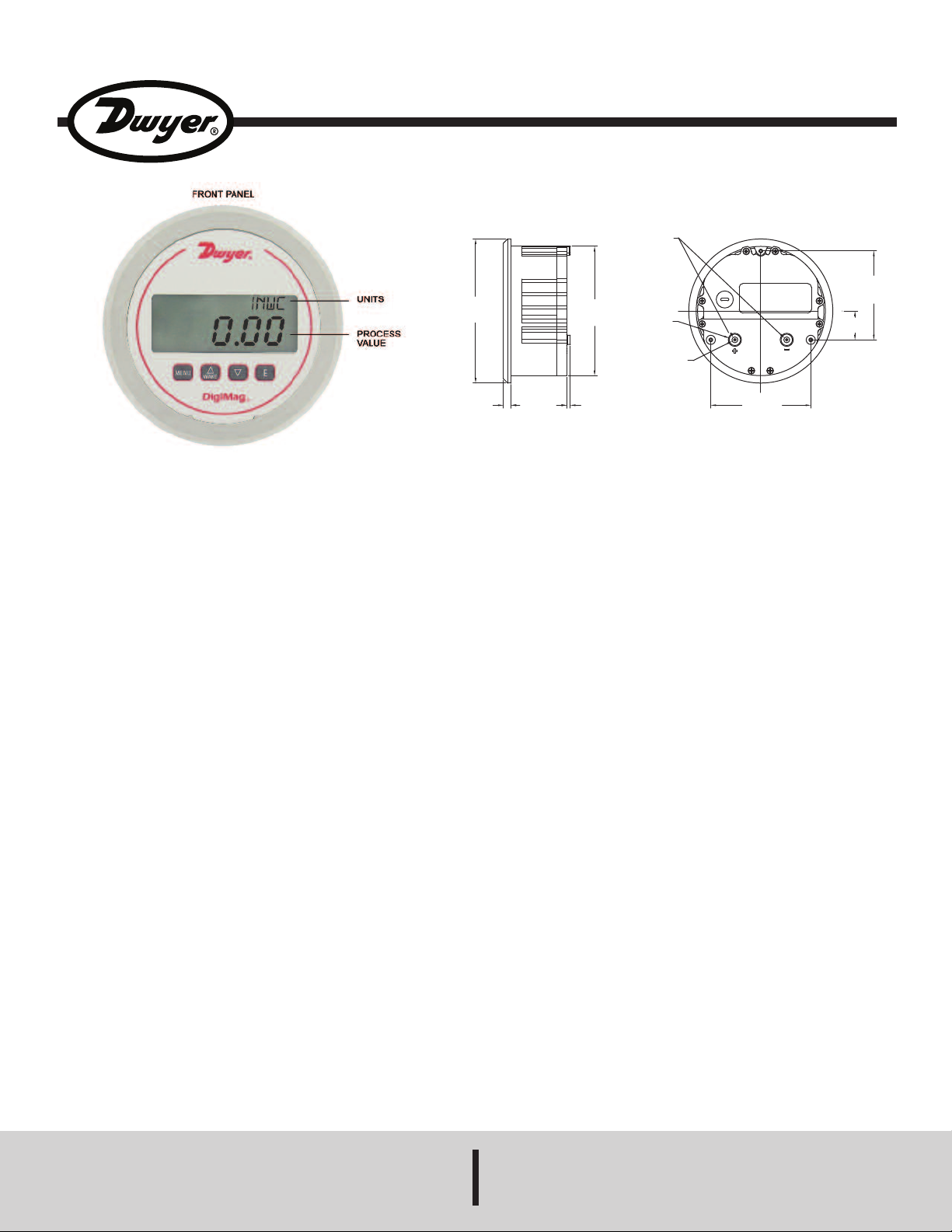
Series DM-1200 DigiMag®Digital Differential Pressure and Air Flow Gage
Specifications - Installation and Operating Instructions
he Series DM-1200 DigiMag
T
s the ideal digital instrument to take the place of analog mechanical pressure
i
ages. The DigiMag
g
ability to be field-programmed to select pressure, air velocity or flow operation. The
®
DigiMag
applications where a set point can be input where the display will blink when the
filter is dirty, alerting the user that a maintenance action needs to occur.
Programming the Series DM-1200 is easy using the menu key to access 4
simplified menus which provide access to: Security level; engineering units; Kfactor for use with various Pitot tubes and flow sensors, circular or rectangular duct
size for volumetric flow operation; filter set point; view peak and valley process
readings; digital damping for smoothing erratic process applications; display
update to conserve battery life; zero and span field calibration.
The Series DM-1200 DigiMag
possesses a full-scale accuracy of 1% on ranges down to 2˝ w.c. and 2% accuracy
down to the very low ranges of 1˝ to 0.25˝ w.c. DigiMag
Pressure Gages offer power versatility by working with 9-24 VDC line power or
simply 9V battery power. If using line power and connecting the 9V battery, the
battery will act as a back-up if line power is lost or interrupted.
Digital Differential Pressure Gages have an added feature for filter
®
®
igital Differential Pressure and Air Flow Gage
D
igital Gages are more versatile than analog gages with their
D
®
Digital Differential Pressure and Air Flow Gage
®
Digital Differential
PECIFICATIONS
S
ervice: Air and non-combustible, compatible gases.
S
etted Materials: Consult factory.
W
Housing Materials: Glass filled plastic.
Accuracy: ±1% F.S. including linearity, hysteresis and repeatability; ±2% F.S. for
ranges 1˝ w.c. and below.
Temperature Limits: 0 to 140°F (-18 to 60°C).
Compensated Temperature Limits: 32 to 122°F (0 to 50°C).
Long Term Stability: ±1% F.S. per year.
Thermal Effect: ±0.05% F.S./°F typ.; ±0.10% F.S./°F for ranges 1˝ w.c. and
below.
Display: 4-digit LCD (Digits: 0.60˝H x 0.33˝W).
Display Update: Selectable for 1 second to 10 minutes or update only from
button push.
Pressure Limits: 5˝ w.c. and lower = 2 psi (13.7 kPa) 10˝ w.c. and higher = 11
psi (75 kPa).
Power Requirements: 9V battery or external power supply 9-24 VDC. Battery
included but not connected.
Type of Battery: 9V alkaline battery (Duracell
Battery Service Life: Battery life depending on the Display Update setting: 150
hours (typical) if Display Update = 1 second; 9 months (typical) if Display Update
= 10 minutes; 1.5 years (typical) if Display Update is disabled. Battery may last
up to four times longer when using lithium-based battery ULTRALIFE U9VL-J.
Current Consumption: 5 mA maximum.
Electrical Connections: Removable terminal block for 16 to 26 AWG.
Electrical Entry: Cable gland for 0.114 to 0.250˝ (2.9 to 6.4 mm) diameter cable.
Process Connections: 3/16˝ I.D. tubing (5 mm I.D.), maximum O.D. 3/8˝ tubing.
Enclosure Rating: NEMA 4X (IP66).
Weight: 1.18 lb (535 g).
Size: 5˝ (127 mm) O.D. front face.
Agency Approvals: CE, EN 61326-1 [Immunity Test Requirement for Industrial
Environments] with the following SPEC:
IEC61000-3-2
IEC61000-3-3
IEC61000-4-2
IEC61000-4-3
IEC61000-4-4
IEC61000-4-5
IEC61000-4-6
IEC61000-4-11
®
Duracell
is a registered trademark of The Gillette Company.
®
PC 1604 or equivalent).
DWYER INSTRUMENTS, INC.
P.O. BOX 373 • MICHIGAN CITY, INDIANA 46360, U.S.A. Fax: 219/872-9057 e-mail: info@dwyer-inst.com
Phone: 219/879-8000 www.dwyer-inst.com
Page 2
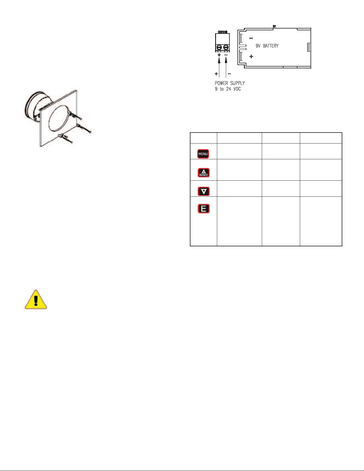
NSTALLATION
I
ounting
M
vertical position required. That is the position in which all standard models are
A
alibrated at the factory. Provide a 4-9/16˝ diameter opening in panel. Insert gage
c
and secure in place with provided screws and adapters.
Included Accessories:
ounting lugs –3
M
-20 x 2-1/2 screws –3
6
-20 x 3/8 screws – 3 (mounting hole depth is 3/8˝ [9.53])
4
able gland –1
C
PERATING INSTRUCTIONS
O
Key Functions
IGURE 1
F
Pressure Connections
Two integral tubing connections are provided on the back of the gage. They are
sized to fit 3/16˝ (4.8 mm) I.D. x 5/16˝ (7.9 mm) O.D. flexible PVC tubing. To
easure single positive pressure, connect tubing to the + port and vent the – port
m
o atmosphere. To measure single negative pressure (vacuum), connect tubing to
t
he – port and vent the + port to atmosphere. To measure differential pressure,
t
connect higher pressure to the + port and lower pressure to the – port. Be sure the
pressure rating of the tubing exceeds that of the operating ranges.
Electrical Connections
A 9V battery or an external power supply 9-24 VDC can be used to power the unit.
If both battery and external power supply are connected, the battery will work as
back up power.
Battery Installation
The unit is shipped with a separate 9V alkaline battery. Remove the unit’s top back
cover then connect the 9V battery to the battery holder as shown in Figure 1.
External Power Supply Installation
Remove the unit’s back cover then connect the external power supply to the
terminal block as shown in Figure 1.
CAUTION: POWER MUST BE OFF WHILE WIRING
CONNECTIONS ARE BEING MADE. DO NOT EXCEED
SPECIFIED SUPPLY VOLTAGE RATINGS. PERMANENT
DAMAGE NOT COVERED BY WARRANTY WILL RESULT.
enu
M
Up Arrow
own Arrow
D
Enter
Home Position
Function
llows access to the
A
enus
m
Displays pressure
readings instantly
(rAtE KEY MODE only)
Displays full scale
range of unit
Main Menu
Function
eturn to home
R
osition
p
Sequences through
menus
equences through
S
enus
m
Enter into SUB
MENU
ub Menu
S
unction
F
eturn to previous
R
menu
Increments a value
Decrements a value
hanges a value or
C
setting. Press
ENTER and display
will blink. Adjust with
UP or DOWN
arrows. Press
ENTER to store.
Display will stop
blinking.
Page 3

enu Map
M
Page 4

AIN MENU PROGRAMMING INSTRUCTIONS
M
Upper Right Display Reads MENU)
(
ecurity Menu
S
SECr-MENU
:
Lock out access to all menus or lock out access to all menus except Auto-Zero
function (Auto-ZERO).
peration Menu
O
elect the measurement type – pressure, velocity or flow and corresponding
S
ngineering units.
e
OPEr-MENU
:
Display Menu: diS-MENU
Monitor and adjust display related settings: Filter type, filter point, dampening,
display update, peak and valley.
dvanced Menu
A
erform auto-zero or full-scale calibration.
P
AdU-MENU
:
VAILABLE VELOCITY RANGES
A
nput Range
I
FPM Range
n w.c.
i
0 - 0.25
0 - 0.50
0 - 1.00
- 2.00
0
- 5.00
0
- 10.0
0
- 15.0
0
0 - 25.0
0 - 50.0
LO (Flow) SUB MENU:
F
or flow measurements, the following units are available:
F
LO – SCFM: Flow – Standard cubic feet per minute
F
FLO –M
S
0 - 2002
0 - 2832
0 - 4004
- 5663
0
- 8954
0
- 12.66 x 1K
0
- 15.51 x 1K
0
0 - 20.02 x 1K
0 - 28.32 x 1K
3
H: Flow – Cubic meters per hour
/S Range
M
0 - 10.17
0 - 14.39
0 - 20.35
- 28.77
0
- 45.48
0
- 64.33
0
- 78.76
0
0 - 101.7
0 - 143.9
SECURITY MENU
: SECr-MENU
With the gage reading pressure (home position), press and hold the MENU key
ntil the SECr-MENU is displayed. Press the E key to show the security SUB
u
ENU SECr–0001. When the security SUB MENU is selected, the present
M
ecurity level is displayed in the upper right hand display. To change the security
s
level, adjust the number displayed to the number shown in the following table for
the desired security level.
ecurity Level
S
Displayed
1
2
ccess
A
All menus access
All menus locked except
assword Value
P
o Enter
t
0
1
90
the Auto-zero function
ll menus locked
3
A
111
The password values shown in the table cannot be altered, so retain a copy of
these pages for future reference.
OPERATION MENU
: OPEr-MENU
With the gage reading a numerical value (home position), press and hold the
MENU key until the SECr-MENU is displayed. Press the q key to show the OPErMENU. Press the E key to show the Operation SUB MENUS.
The Operation SUB MENUS are:
PrES – Pressure UEL – Velocity FLO – Flow
FLOr – Flow range KFAC – K Factor ArEA – Area
DIA – Diameter XDIM – X Dimension YDIM – Y Dimension
If the instrument is set for Velocity, the OPEr MENU will have an additional KFAC
SUB MENU. If the instrument is set for Flow, the OPEr MENU will have additional
KFAC and ArEA SUB MENUS. These will be discussed under Velocity and Flow.
NOTE: When scrolling through the OPEr SUB MENUS, the measurement type
the unit is currently set for will show the units in the upper right display. The
other measurement types will have a blank upper right display (see below).
FLOr (Flow range) SUB MENU:
The following flow ranges are available:
LOr – HI: Flow range – High: 999.9 x 1K
F
LOr – MED: Flow range – Medium: 99.99 x 1K
F
LOr – LO: Flow range – Low: 9999
F
able 1: FLOr = LO
T
aximum Duct Size (English)
M
Max Duct Size
sq ft
4.994
.531
3
.497
2
1.766
1.117
0.789
0.644
0.499
0.353
Max Duct Size
sq ft
49.94
35.31
24.97
17.66
11.17
7.898
6.446
4.994
3.530
.50
.00
SCFM
Range
9999
999
9
999
9
9999
9999
9999
9999
9999
9999
SCFM
Range
99.99x1K
99.99x1K
99.99x1K
99.99x1K
99.99x1K
99.99x1K
99.99x1K
99.99x1K
99.99x1K
Range
in w.c.
0.25
0
1
2.00
5.00
10.0
15.0
25.0
50.0
Table 3: FLOr = MED
Maximum Duct Size (English)
Range
in w.c.
0.25
0.50
1.00
2.00
5.00
10.0
15.0
25.0
50.0
T
M
Table 4: FLOr = MED
Maximum Duct Size (Metric)
able 2: FLOr = LO
aximum Duct Size (Metric)
Range
in w.c.
0.25
.50
0
.00
1
2.00
5.00
10.0
15.0
25.0
50.0
Range
in w.c.
0.25
0.50
1.00
2.00
5.00
10.0
15.0
25.0
50.0
3
M
/hr
Range
9999
999
9
999
9
9999
9999
9999
9999
9999
9999
3
M
/hr
Range
99.99x1K
99.99x1K
99.99x1K
99.99x1K
99.99x1K
99.99x1K
99.99x1K
99.99x1K
99.99x1K
Max Duct Size
M
0.273
.193
0
.136
0
0.096
0.061
0.043
0.035
0.027
0.019
Max Duct Size
M
2.731
1.930
1.364
0.965
0.610
0.431
0.352
0.273
0.193
2
2
UEL (Velocity) SUB MENU:
For velocity measurement, the following units are available:
UEL-SFPM: Velocity – Standard feet per minute
UEL-M/S: Velocity – Meters per second
NOTE: Air velocity and flow readings are based upon standard dry air
conditions with an ambient temperature of 70°F and a barometric pressure of
29.92 INHG.
Table 5: FLOr = HI
Maximum Duct Size (English)
Range
in w.c.
0.25
0.50
1.00
2.00
5.00
10.0
15.0
25.0
50.0
SCFM
Range
999.9x1K
999.9x1K
999.9x1K
999.9x1K
999.9x1K
999.9x1K
999.9x1K
999.9x1K
999.9x1K
Max Duct Size
sq ft
499.4
353.1
249.7
176.6
111.7
78.98
64.46
49.94
35.30
Table 6: FLOr = HI
Maximum Duct Size (Metric)
Range
in w.c.
0.25
0.50
1.00
2.00
5.00
10.0
15.0
25.0
50.0
3
M
/hr
Range
999.9x1K
999.9x1K
999.9x1K
999.9x1K
999.9x1K
999.9x1K
999.9x1K
999.9x1K
999.9x1K
Max Duct Size
2
M
27.31
19.30
13.64
9.654
6.107
4.317
3.526
2.731
1.931
Page 5

FAC (K Factor) SUB MENU:
K
.00-KFAC: K Factor = 1.00
1
K factor becomes accessible if the instrument is set for Velocity or Flow. When the
®
DigiMag
is used with a Pitot tube, the manufacturer may specify a K factor. The
adjustment range is 0.01 to 2.00. The factory setting is 1.
rEA (Area), DIA (Diameter), XDIM (X dimension) and YDIM (Y dimension)
A
UB MENUS:
S
These SUB MENUS become accessible if the instrument is set for Flow. When
measuring flow, the area of the duct must be specified. Tables 1 to 6 show the input
range vs. maximum flow and duct size. For a rectangular duct the maximum size
s specified by the X, Y dimensions. For a circular duct the maximum size is
i
pecified by the diameter. X, Y and circular dimensions are entered in feet with
s
.001 foot resolution for FLOr = LO, 0.01 foot resolution for FLOr = MED and 0.1
0
foot resolution for FLOr = HI, or entered in millimeters with 1 millimeter resolution.
ArEA – Area, select CIR for a circular duct or RECT for a rectangular duct. If a
circular duct is selected the DIA SUB MENU will be activated. If a rectangular duct
s selected, the XDIM and YDIM SUB MENUS will be activated.
i
IA – Diameter, enter the diameter of a duct
D
XDIM – Enter the “X” dimension of a duct
YDIM – Enter the “Y” dimension of a duct
ISPLAY UPDATE SETTING
D
ith the LCD reading rAtE – NORM, press the E key; the display will blink. Press
W
he q key to change the display update rate then press the E key to save the
t
esired display update rate.
d
rAtE – NORM: Display update = Normal (1 second).
The gage reads the process pressure and updates the LCD every second.
AtE – 10: Display update = 10 minutes.
r
he gage reads the process pressure and updates the LCD every 10 minutes.
T
rAtE – KEY (On-Touch mode): Display update is disabled.
The gage reads the process pressure and updates the LCD whenever the p key
is pressed. If the p key is released, the LCD will hold and display the last pressure
eading.
r
OTES:
N
1. Depending on the Display Update setting, the battery life is shown below:
-150 hours (typical) if Display Update is set for “Normal” 1 second update. rAtE-
NORM
-1 year (typical) if Display Update is set for 10 minutes. rAtE-10
2 years (typical) if Display Update is disabled. rAtE-KEY
-
. If the Display Update is set for 10 minutes or disabled (On-Touch mode), the
2
rocess pressure value can be read instantly by pressing and holding the p key
p
on the front panel. Also the LCD will automatically show “ALAr” if the filter point has
been exceeded.
PEAK AND VALLEY SETTING
00.0 – PEAK: Peak value = 100.0
1
he peak feature stores the highest pressure reading the instrument has measured
T
ince the last reset or power up. At power up PEAK is reset to the present pressure
s
reading. To manually reset the PEAK value, press the E key while in the PEAK
SUB MENU.
DISPLAY MENU: diS – MENU
With the gage reading a numerical value (home position), press and hold the
MENU key until the SECr-MENU is displayed. Press the q key until the LCD
shows diS – MENU. Press the E key to show the Display SUB MENUS.
FILTER TYPE SETTING
With the LCD reading FILt – OFF, press the E key; the display will blink. Press the
q key to change the filter type then press the E key to save the desired filter type.
FILt – OFF: Filter type = OFF. The filter function is disabled.
FILt – HIGH: Filter type = HIGH. The display blinks when pressure is greater than
the filter point.
FILt – LOW: Filter type - LOW. The display blinks when pressure is less than the
filter point.
FILTER POINT SETTING
With the LCD reading 0.00 – SPPT, press the E key; the display will blink. Press
the p or q key to change the filter point then press the E key to save the desired
filter point.
0.00 – SPPT: Filter point = 0.00. The filter point may be set to anywhere within the
range of the instrument.
DAMPING SETTING
With the LCD reading 1 – DAMP, press the E key; the display will blink. Press the
p or q key to change the damping level then press the E key to save the desired
damping level.
1 – DAMP: Damping level = 1. The damping level can be adjusted from 1 to 15.
Damping stabilizes the display from instabilities due to things such as vibration and
excessive pressure fluctuations. The damping function adjusts the amount of
readings that are averaged for each display update.
0.0 – VALY: Valley value = 0.0
The valley feature stores the lowest pressure reading the instrument has measured
since the last reset or power up. At power up VALY is reset to the present pressure
reading. To manually reset the VALY value, press the E key while in the VALY SUB
MENU.
ADVANCED MENU: AdU – MENU
With the gage reading pressure (home position), press and hold the MENU key
until the SECr-MENU is displayed. Press the q key until the display shows the
AdU – MENU. Press the E key to show the advanced function SUB MENUS.
Auto ZERO: auto-zero
NOTE: For accurate calibration, DO NOT apply any pressure when
performing this function.
With the display reading Auto ZERO, release pressure to Zero then press the E
key; the display will blink. Press the E key again to complete the Auto-zero.
CAL – SPAN: full-scale calibration
With the display reading CAL – SPAN, apply full-scale pressure then press the E
key; the display will blink. Press the E key again to save the full-scale calibration
or press the MENU key to cancel the calibration.
MAINTENANCE
Upon final installation of the Series DM-1200 DigiMag
®
Digital Differential Pressure
Gage, no routine maintenance is required. A periodic check of the system is recommended. The Series DM-1200 is not field serviceable and should be returned if repair
is needed (field repair should not be attempted and may void warranty). Be sure to
include a brief description of the problem plus any relevant application notes. Contact
customer service to receive a return good authorization number before shipping.
Page 6

3-5/64
[78.27]
STANDARD MOUNTING HOLE
DIMENSION FOR DIGIMAG GAUGE
Ø4-9/16 [115.89]
1
[25.44]
2X30°
2xØ13/32 [10.32]
THRU HOLES FOR
PRESSURE PORTS
1-51/64 [45.72]
3-15/32 [88.12]
(3) SURFACE MOUNTING
HOLE LOCATIONS
13/32 [10.16]
Ø5/8 [15.88]
THRU HOLE FOR
CONDUIT CONNECTION
OUTSIDE DIAMETER
OF A-286 FLANGE
1-1/4 [31.75]
(3) FLANGE MOUNTING
HOLE LOCATIONS
Ø5-17/32 [140.49]
BOLT CIRCLE
MOUNTING HOLE DIMENSION
FOR A-286 FLANGE
Ø5-1/8 [130.18]
Mounting Template
©Copyright 2014 Dwyer Instruments, Inc Printed in U.S.A. 1/14 FR# 19-443779-50 Rev.2
DWYER INSTRUMENTS, INC.
P.O. BOX 373 • MICHIGAN CITY, INDIANA 46360, U.S.A. Fax: 219/872-9057 e-mail: info@dwyer-inst.com
Phone: 219/879-8000 www.dwyer-inst.com
 Loading...