

Page 1
USER’S GUIDE
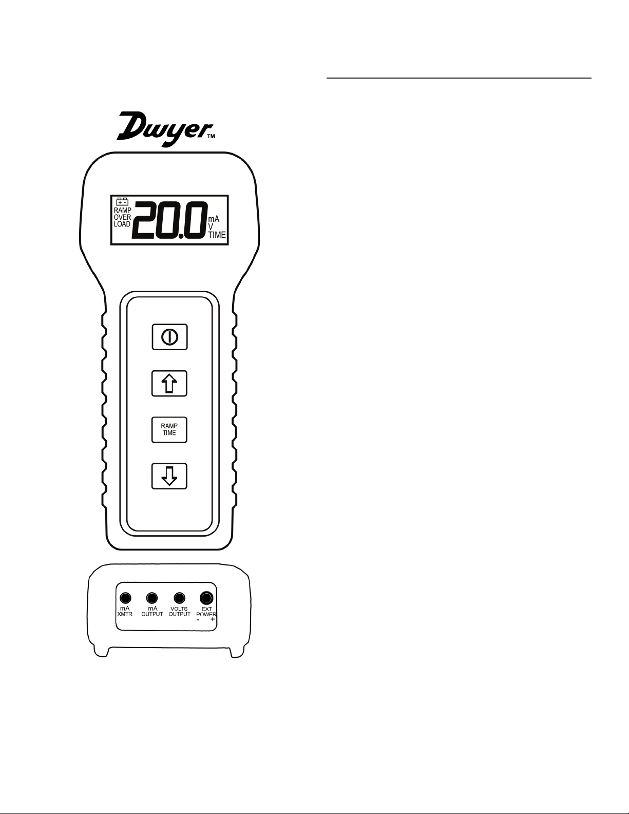
Model CSG
Current & Voltage Calibrator
Specications
OUTPUTS
Ranges
Current: 0.0 to 20.0mA DC in 1mA steps
Voltage: 0.0 to 10.0V DC in 1V steps
Accuracy at 25°C
Current: +/- 0.05mA DC
Voltage: +/- 0.05V DC
Load Impedance
Current: 300 ohms maximum
Voltage: 1000 ohms minimum
External mA Transmitter Source
Voltage: 12V minimum to 30V peak maximum
RAMPING
Manual Anywhere in range
Auto
Values: User adjustable Min. & Max. values
anywhere within range
Step Time: User adjustable from 1 to 20
seconds, in 1 second increments
DISPLAY
Numerical LCD, 00.0 to 99.9, 0.59”H (15mm)
Copyright © 2006. All rights reserved including the
right of reproduction in whole or in part in any form
Annunciators “RAMP”, “OVER LOAD”, “mA”, “V”,
“TIME”, and symbol for low battery
Blue Backlight Energized with momentary side
switch
ENVIRONMENT
Operating 32 to 122°F (0 to 50°C)
POWER
9V Battery NEDA1604, JIS006P, or IEC6F22
(Duracell MN1604 or equivalent)
Up to 30 hours continuous use
Low Battery Indicator comes on below
approximately 7 volts
120 V AC Plug-in 9V DC output supply for
bench-top use
Auto Power Off User adjustable delay time from
1 to 20 minutes after last key press
Can also be disabled
MECHANICAL
Dimensions 5.5”H x 2.5”W x 1.4”D
(140H x 63.5W x 35.6D mm)
Weight 6 oz (170 g)
Page 2

Operating Instructions
POWER ON/OFF
Make sure that the battery is installed or the AC adapter is
plugged into the EXT POWER jack. The AC adapter disconnects the
internal battery.
To turn the CVC on, press and hold the upper red ON/OFF button for at least 2 seconds. The LCD annunciators will cycle and then hold
steady when the CVC is turned on. Release the ON/OFF button within 5
seconds after cycling stops or the unit will turn off.
To turn off, press and hold the ON/OFF button for at least 5
seconds. The LCD annunciators will start to cycle when the CVC is turned
off. Release the ON/OFF button as soon as the display starts to cycle or the
unit will turn on again.
SELECTING OUTPUT MODE
Plug the test lead assembly into the appropriate output jack
as shown below. If the test leads are plugged into the mA XMTR or mA
OUTPUT jack, or no leads are plugged in, “mA” will turn on. If the load
resistance is too high or the leads are left open, “OVERLOAD” will turn on.
If the leads are plugged into the VOLTS OUTPUT jack, “V” will turn on. If
the load resistance is too low or the leads are shorted, “mA” may stay on
or turn on.
Fig 1. Voltage Output Fig. 2 mA Source Output
MANUAL SELECTION OF OUTPUT LEVEL
To increase the output, press the key. To reduce the output,
press the key. New output value will be displayed on the display.
AUTO RAMPING
The output is preprogrammed to ramp between 4 to 20 mA (or 2
to 10 V) and back in 1.0 mA (or 1.0 V) steps, with 5 seconds between each
step. See below to change the ramp end points and step time interval.
To start ramping the output, press the RAMP/TIME key for 2
seconds. “RAMP” will turn on and the output will start ramping within the
minimum and maximum values programmed into the CVC. It will start at
the output value manually set on the CVC before the key is pressed.
To stop the ramping and return to manual mode, press the
RAMP/TIME key again.
CHANGING THE AUTO RAMPING END POINTS AND STEP TIME
Press and hold the RAMP/TIME key, and immediately (within 2
seconds) press the key without releasing the RAMP/TIME key until
“RAMP” and “TIME “ turn on. “mA” will turn off. Set the time duration for
each step increment from 1.0 to 20.0 seconds, in 1.0 second increments
by using the and keys.
To store the desired time interval, press the RAMP/TIME key
again. “TIME” will turn off and the appropriate “mA” or “V” will ash.
“RAMP” will remain on.
Set the rst end point by using the and keys. To store
the rst end point, press the RAMP/TIME key again. The appropriate “mA”
or “V” and “RAMP” will ash.
Set the second end point by using the and keys. To
store the second end point and exit the programming mode, press the
RAMP/TIME key again. The second value stored will be displayed along
with the appropriate “mA” or “V”.
Fig 3. Simulate a 2-Wire mA Transmitter Loop With External 12 to
30V DC Supply. A similar connection can be used to extend output range
of CVC beyond 300 ohms. A 24V source will allow CVC to source into an
impedance of >1000 ohms.
SETTING THE AUTO POWER OFF DELAY TIME
With the unit ON, press and hold the RAMP/TIME key, and immediately (within 2 seconds) press the key without releasing the
RAMP/TIME key until “TIME” turns on. All other annunciators are off. Set
the time delay from the last key press until the unit automatically turns
OFF by using the and keys. The time delay can be set from
1.0 to 20.0 minutes in 1.0 minute increments. If the delay time is set to
00.0 minutes, the Auto Power Off Delay function is disabled. This is useful
when the unit is used on a bench with the AC adapter.
To store the desired time delay, press the RAMP/TIME key
again. “TIME” will turn off and the appropriate “mA” or “V” will turn on.
Warranty
This product is warranted to be free of defects in material and workmanship for one year from date of shipment under normal use and service.
This warranty does not apply to batteries, lamps, sensors, and other wear
items. This warranty does not apply to defects resulting from the action of
the user such as misuse, improper wiring, operation outside of specication, alteration, accident, unauthorized repair, improper maintenance, or
abnormal conditions of operation.
The manufacturer specically disclaims any implied warranties of merchantability or tness for any particular purpose and will not be liable for
any direct, indirect, incidental or consequential damages. The manufacturer’s total liability is limited to repair or replacement of the product.
If it should be necessary to return the product during or beyond the warranty period, contact customer service where purchased. The sender is
responsible for shipping charges, freight, insurance and proper packaging
to prevent damage in transit.
The warranty set forth above is inclusive and no other warranty, whether
written or oral, is expressed or implied.
 Loading...