

Page 1
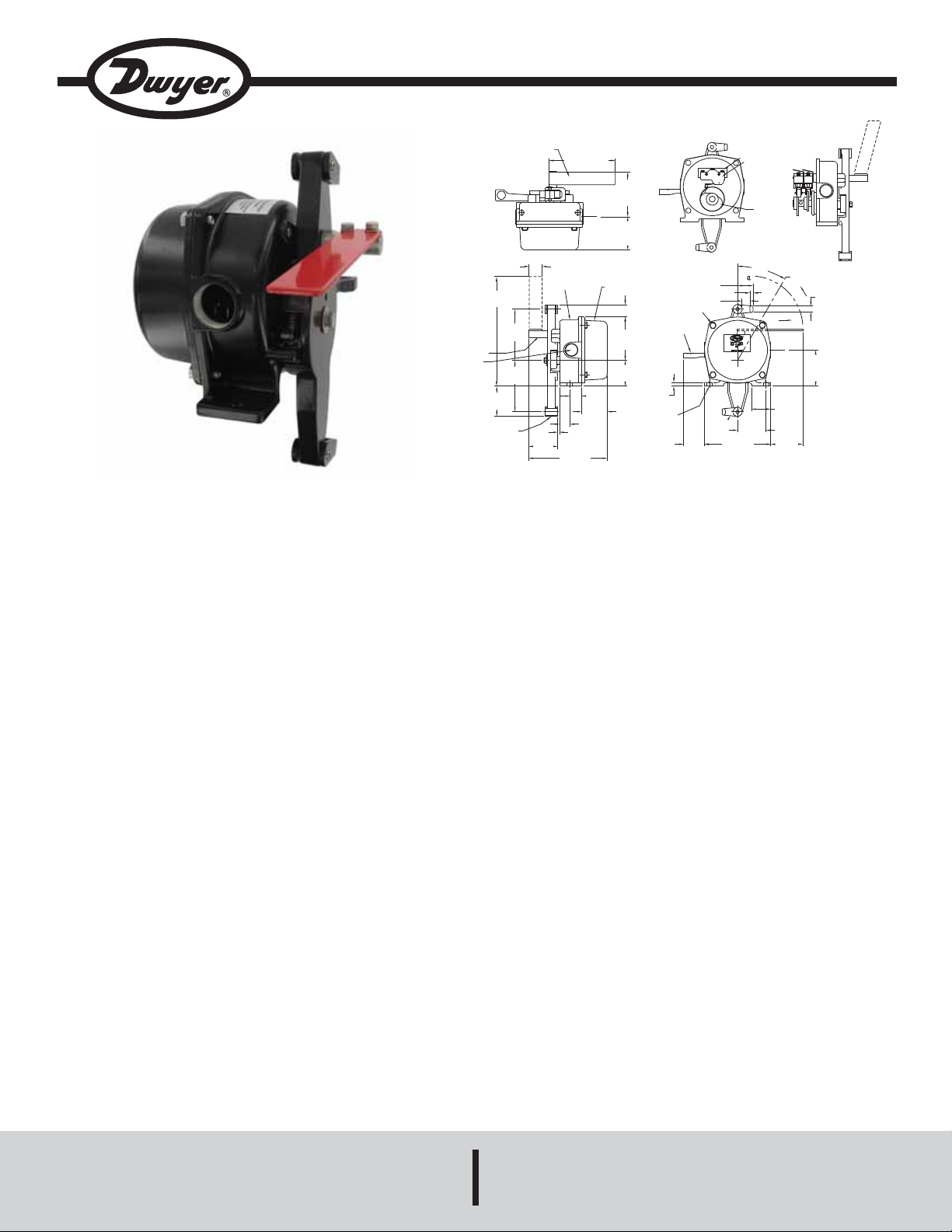
Series CPS Cable Pull Switch
OPERATION-INDICATING
PLATE
INSIDE VIEW
CAMS
INSULATORS
MICROSWITCHES
5-1/8
[130.18]
3-7/16
[87.31]
2-9/16
[65.09]
1-1/8
[28.58]
19/32
[15.03]
COVER BOLTS
4X M10
RESETTING
LEVER
63/64
[25]
CASE
COVER
61/64
[24.21]
3-23/64
[85.33]
1-31/32
[50]
29/32
[23.02]
1-31/32
[50]
51/64
[20.24]
6-1/16
[153.99]
1/8
[3.18]
LEVER
2-21/64
[59.13]
3-15/16
[100.01]
2X 3/4˝
NPT
SHAFT
3-15/16
[100.01]
8-7/16
[214.31]
2-15/64
[5.95]
PULLING DIRECTION
1/4
[6.35]
30°
LOCK POSITION
31/64
[12.3]
2-49/64
[70.25]
2X 2-11/64
[55.17]
2-9/16
[65.09]
2X 1-1/2
[38.1]
5-1/8
[130.18]
1-37/64
[40.08]
9/32
[7.14]
ø13/32 [10.32]
MOUNTING HOLES
SHACKLES
OPERATING DIRECTION
Specifications - Installation and Operating Instructions
Bulletin PC-CPS-1
The Series CPS Cable Pull Switch is designed to provide a
switching system to isolate the power to the conveyor system or
other similar process equipment in event of a shut-down condition. A steel wire is placed along the side of the conveyor and attached to the cable pull switch. When the cable is pulled at any
point along the conveyor it will trip the cable pull switch causing
the conveyor to shut down. To restart the conveyor the CPS
must be manually reset. The series CPS has a universal design
for bi-directional activation and utilizes a highly visible red flag to
indicate the switch status. The compact design makes it ideal for
easy installation.
SPECIFICATIONS
Temperature Limits: -4 to 140°F (-20 to 60°C).
Enclosure: Die cast aluminum.
Enclosure Rating: NEMA 6 (IP 67).
Switch Type: 2 SPDT.
Electrical Rating: 10 amp @ 125/250 VAC; 1/2 amp @ 125
VDC.
Electrical Connection: 3 screw type, common, normally open,
normally closed.
Electrical Conduit: Two 3/4˝ female NPT.
Activation Angles: 30 degrees.
Activation Force: 11 +/- 2.25 pounds.
APPLICATIONS
• Conventional Belt Conveyors
Control Type: Manual reset.
Weight: 6.4 pounds.
• Ship Loading/Unloading Systems
• Stacker/Reclaim Conveyors
• Apron Feeder Conveyors
• Tripper or Shuttle Conveyors
• Bucket Elevators
• Horizontal Feed Systems
Phone: 219/879-8000 www.dwyer-inst.com
DWYER INSTRUMENTS, INC.
P.O. BOX 373 • MICHIGAN CITY, INDIANA 46361, U.S.A. Fax: 219/872-9057 e-mail: info@dwyer-inst.com
Page 2
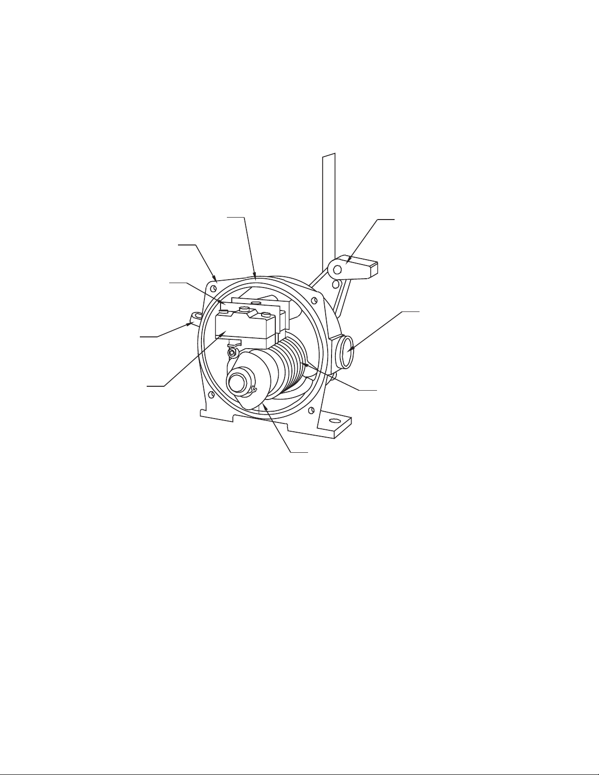
Operation Principle
The CPS is designed to provide a switching system to isolate the
power to conveyor system and other equivalent process
equipment in a shutdown condition. The cable pull switch is
actuated by a steel wire, which is placed along-side the
conveyor. By pulling on the cable at any point, the CPS will
activate when the operating lever rotates 30 degrees clockwise,
automatically locking the switches. The CPS can be reset by
pressing down on the reset lever.
INSULATING PAPER
RESETTING LEVER
MICROSWITCH
CASING
PACKING
OPERATING LEVER
3/4˝ FNPT CONDUIT CONNECTION
SPRING
CAM
Page 3

Installation
Eye bolts should be prepared before installation, and should be
spaced according to the cable length (Figure 2). A single pull
cord up to 50 feet should have an eye bolt mounted every 10
feet. When using a single pull cord up to 75 feet there should be
an eyebolt every 3 feet. The maximum length of cable between
CPS is 75 feet (Note: Variations in temperature will cause cable
to expand and contract). The ideal cord is a steel cable 0.25
inches in diameter. Figure 3 is a typical installation of a CPS.
CONVEYOR BELT FRAME
CABLE
Fig. 2 Installation of Eye Bolts
EYE BOLTS
FRAME OF BELT
CONVEYOR
CABLE
MOUNTING
BASE
6˝
WIRE CUP
4.5˝
8.25˝
Fig. 3 Typical Installation of CPS
Page 4

Wiring
The Cable Pull Switch has 2 SPDT relays that can be accessed
by removing the cover. The independent relays can be used to
control two separate circuits such as a motor starter and a signal
light.
TERMINAL SCREW
ROLLER LEVEL
COM-1, 4
NO- 3, 6
NC- 2, 5
DEACTIVATEDACTIVATED
Adjustment
The cams are set at the factory to trip the microswitches when
the operating arm is rotated 30 degrees clockwise. Cams can be
adjusted by loosening the set screw.
MAINTENANCE
Clean excessive amount of dust when it accumulates on the
operating lever. Occasionally check to see if the CPS is working
normally by pulling the cable. After the CPS is installed check the
housing cover to ensure it is tight, water and dust can enter
between the cover and casing if it not tightened correctly causing
the switch to malfunction. The CPS is not field serviceable and
should be returned if any repair is needed (field repair should not
be attempted and may void warranty). Be sure to include a brief
description of the problem plus any relevant application notes.
Contact customer service to receive a returns good authorization
number before shipping.
©Copyright 2009 Dwyer Instruments, Inc. Printed in U.S.A. 7/09 FR# R4-443727-50
DWYER INSTRUMENTS, INC.
Phone: 219/879-8000 www.dwyer-inst.com
P.O. BOX 373 • MICHIGAN CITY, INDIANA 46361, U.S.A. Fax: 219/872-9057 e-mail: info@dwyer-inst.com
 Loading...