

Page 1
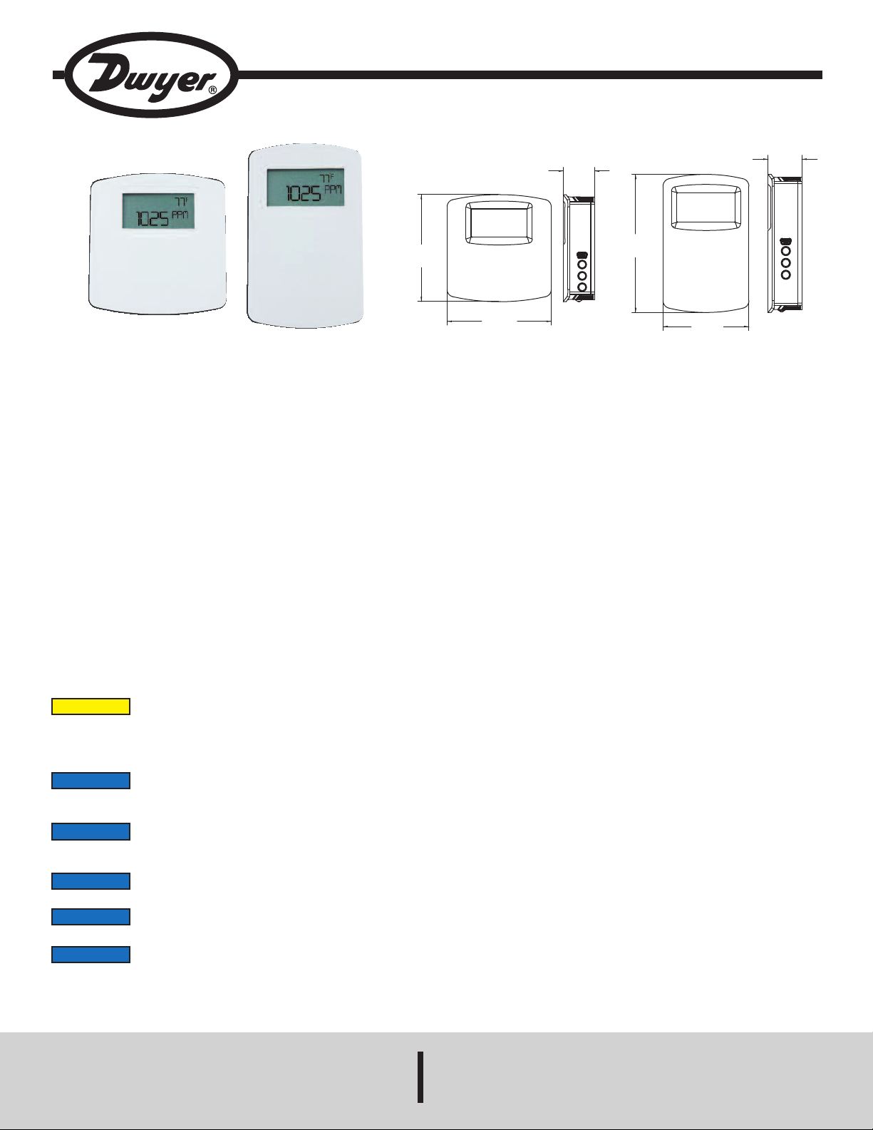
Series CDTA Communicating Carbon Dioxide Detector
3.65
[92.72]
3.56
[90.42]
1
.08
[
27.33]
4.50
[114.30]
2.80
[71.12]
1
.10
[
27.96]
Specifications - Quick Start Installation and Operating Instructions
European North American
The Series CDTA Communicating Carbon Dioxide Detector combines the
function of three room sensors into a single, compact housing. Parameters include
arbon dioxide, humidity, temperature, and temperature set point with override. By
c
aving field selectable Modbus
h
eeded for power and the communication signal. The communicating detectors
n
can be daisy-chained together to further reduce installation cost. In order to reduce
the set up time, the RS-485 MAC address is set up using on board dip switches.
A second set of dip switches are used to select whether output is Modbus
BACnet MS/TP communication protocols and to limit access to the set up menu.
Like our Series CDT Carbon Dioxide Transmitter, the Series CDTA uses a Single
Beam Dual Wavelength Non-Dispersive Infrared (NDIR) sensor to measure the
carbon dioxide level. This technology can be used in installations that will be
occupied 24 hours per day. For improved accuracy, the transmitter can be field
calibrated to the environmental conditions of the installation. Also, the barometric
pressure can be programmed to correct for altitude. The humidity uses a capacitive
polymer sensor and the temperature is measured using a 10KΩ thermistor sensor.
The humidity sensor is field replaceable without the need for additional calibration.
Optional local and remote displays are available to display any of the parameters.
For applications in which the building occupants aren’t familiar with CO
concentrations, the LCD can be programmed to display temperature, humidity, or
temperature set point instead.
Installation
CAUTION
Disconnect power supply before installation to prevent electrical
shock and equipment damage.
®
nd BACnet Communications, only four wires are
a
®
RTU or
Bulletin AQ-CDTA-QS
PECIFICATIONS
S
Sensor (CO
Humidity: Capacitive polymer;
Temperature: Solid state band gap.
Range:
C
Accuracy:
CO
RH: ±2% (10 to 90% RH);
Temperature: ±1°C @ 25°C.
Temperature Dependence (CO
Non-Linearity (CO
Pressure Dependence (CO
Response Time (CO
Temperature Limits: 32 to 122°F (0 to 50°C).
Humidity Limits: 10 to 95% RH (non-condensing).
Power Requirements: 10 to 42 VDC / 10 to 30 VAC.
Power Consumption:
2
Average: 0.5 watts;
Peak: 1.2 watts.
Output: 2-wire RS-485, Modbus
protocol.
Weight: 4.4 oz (125 g).
Agency Approvals: BTL, CE, RoHS.
): Single-beam, dual-wavelength NDIR;
2
O
0 to 2000 or 5000 PPM CO2 (depending on model);
:
2
umidity: 0 to 100% RH;
H
emperature: 32 to 122°F (0 to 50°C).
T
2
: ±40 ppm ±3% of reading;
): ±8 ppm / °C at 1100 ppm.
): 16 ppm.
2
): 2 minutes for 99% step change.
2
2
): 0.13% of reading per mm of Hg.
2
®
RTU or BACnet MS/TP communication
Make sure all connections are in accordance with the job wiring diagram and in
accordance with national and local electrical codes. Use copper conductors only.
NOTICE
Use electrostatic discharge precautions (e.g., use of wrist
straps) during installation and wiring to prevent equipment
damage.
NOTICE
For optimal performance, self calibration feature of the
transmitter requires exposure to normal outdoor equivalent
carbon dioxide level once every thirty days.
NOTICE
Avoid locations where severe shock or vibration, excessive
moisture or corrosive fumes are present.
NOTICE
Do not exceed ratings of this device, permanent damage not
covered by warranty may result.
NOTICE
Upon powering the transmitter, the firmware version will flash on
the display. A warm up period of 30 minutes is required for the
transmitter to adjust to the current CO
concentration.
2
Modbus® is a registered trademark of Schneider Automation, Inc.
DWYER INSTRUMENTS, INC.
Phone: 219/879-8000 www.dwyer-inst.com
P.O. BOX 373 • MICHIGAN CITY, INDIANA 46360, U.S.A. Fax: 219/872-9057 e-mail: info@dwyer-inst.com
Page 2
igure 1: Removal Of Cover From Back Plate
F
OUNTING
M
. Push tab on top and bottom of cover and lift cover from back plate (See Figure 1).
1
. Select the mounting location, away from diffusers, lights or any external
2
influences.
3. Mount transmitter on a vertical surface to a standard electrical box using the two
#6 M2C type screws provided.
4. Pull wires through sub base hole and make necessary connections.
. Reattach cover to base plate.
5
IRING
W
NOTICE
iring should comply with Electrical Characteristics of
W
Generators and Receivers for Use in Balanced Digital Multipoint
Systems, TIA/EIA-485-A-1998, Telecommunications Industry Association, 1998.
BACnet installations should comply with ANSI/ASHRAE Standard 135-2010
ACnet A Data Communication Protocol for Building Automation and Control
B
etworks, American Society of Heating, Refrigerating and Air-Conditioning
N
Engineers, Inc., 2010.
®
Modbus
Serial Line Specification and Implementation Guide V1.02, Modbus
installations should comply with Modbus®Communication Protocol over
®
Organization,
Inc., 2006
igure 3 shows how to connect the CDTA in a network containing individual local
F
upplies. Use a cable containing a twisted pair and a single conductor. The pair is to
s
e used for B(+) and A(-). The single conductor is to be used for common. Both AC
b
and DC supplies are suitable for this configuration.
In either configuration you must use shielded cable. Connect the shield to earth
round at one location only to prevent ground loops.
g
ll devices in the network should be daisy chained. Star connections and T
A
onnections are not permitted.
c
The B(+) and A(-) lines must be terminated at both ends with a 120 ohm resistor. If
the CDTA is an end device it has an on-board resistor that may be used. See DIP
WITCH SETTINGS to enable it.
S
ip Switch Configuration
D
igure 4: Dip Switch SW2 (Center-Left)
F
Use DIP Switch SW2 (see Figure 4) to configure the RS-485 MAC address of the
evice. A valid address depends on the protocol selected. Valid BACnet addresses
d
ange from 0 to 127. Valid Modbus
r
evice is shipped with BACnet selected and the address set to 127 (as shown in
d
®
ddresses range from 1 to 247. By default, the
a
Figure 4). A valid and unused address should be set before connecting to an existing
network. The device will not function properly if an invalid address is set. During the
power up sequence, the LCD (if present) will display the RS-485 address as the
primary value with “ADR” as the primary text and either “BAC” to indicate BACnet or
“MOD” to indicate Modbus
®
as the secondary text. If the RS-485 MAC address is
invalid, the invalid value is shown as the primary value with “ERR” as the primary text.
Communications wiring must be in a daisy-chain fashion. Star connections are not
permitted.
Cable shield must be connected to earth ground at one location only.
Figure 2
Figure 2 shows how to connect the CDTA in a network containing a common power
supply. Use a cable containing two twisted pairs. One pair is to be used for B(+) and
A(-). The other pair is to be used for power and common. This configuration is not
suitable for AC supplies. Use a DC supply only. Care should be taken that there are
not too many devices powered from the same supply as voltage drops will occur in
the wiring. If you have many devices, or have long cable runs, the local supply
configuration may be a better choice.
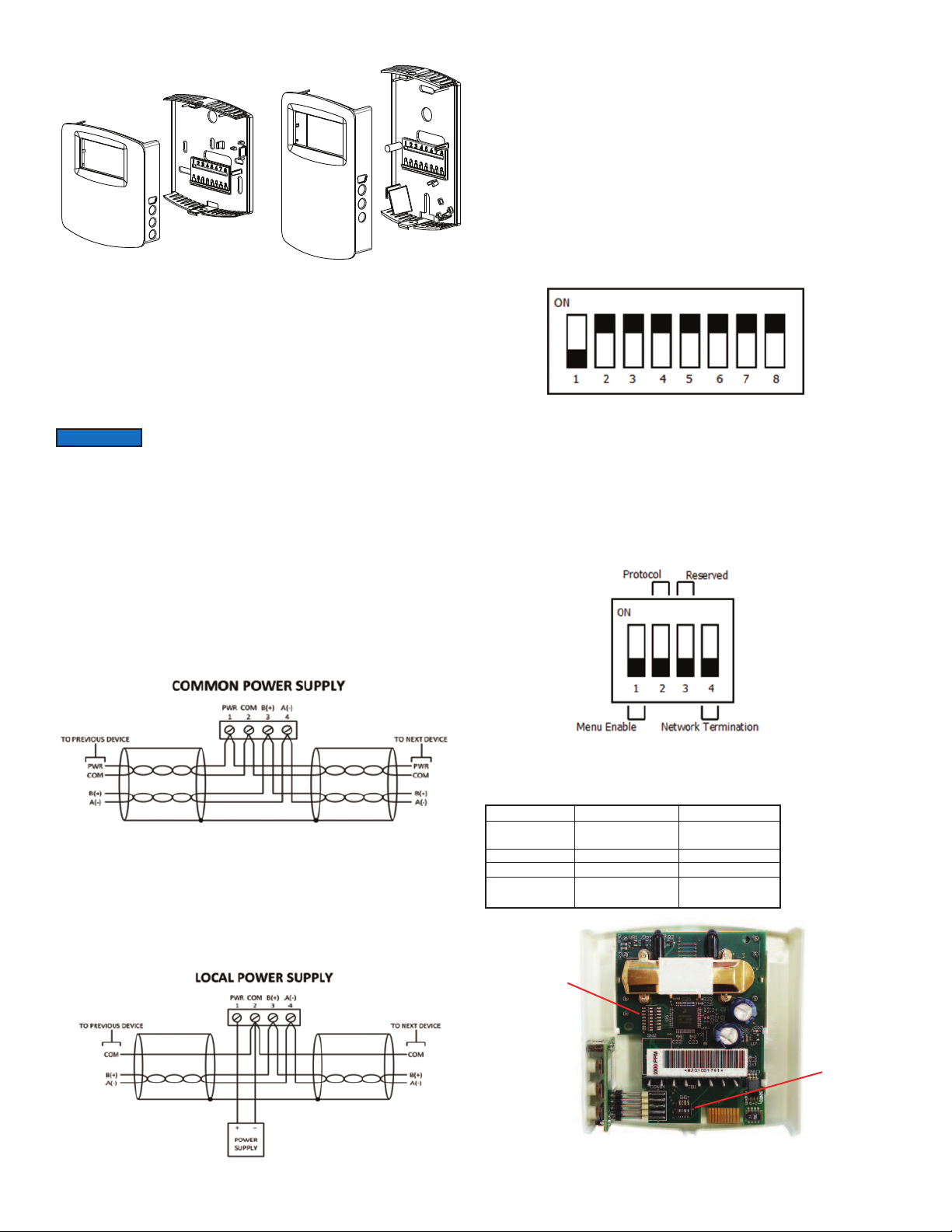
Figure 5: Dip Switch SW1 (Bottom-Center)
Use DIP Switch SW1 (see Figure 5) to configure other hardware and software
options.
Switch
1 - Menu Enable
2 - Protocol
On
Access to the setup
menu is enabled.
Modbus
Off
Access to the setup
menu is disabled.
BACnet
3 - Reserved
4 - Terminating
Resister
120Ω Between A (-)
and B (+)
Open
Dip Switch
SW2
Dip Switch
SW1
Figure 3
Internal View of Transmitter
Figure 6
Page 3

igure 7: Display Layout
F
Home Screen
The home screen displays up to two parameters during normal operation. The
parameters displayed on the home screen can be changed by the “DSP” setting in
he setup menu.
t
et Point
S
When in the home display, a single press of either the UP or DOWN button will
display the current temperature set point value. Additional presses of the UP or
DOWN buttons will increase or decrease the set point by 1 degree per button
depression. Holding the UP or DOWN button will continuously change the set point
alue until the button is released. The set point display will timeout and return to the
v
ome screen after 5 seconds of inactivity. At this point the new set point value is
h
tored in non-volatile memory. The range of the set point value can be configured
s
with “SOH” and “SOL” values in the setup menu. A display is not required to
change the set point value.
Override
When on the home screen or when changing the set point, the override button
(middle button) can be pressed. When the override button is pressed, a snow flake
symbol is displayed momentarily to indicate the button was pressed.
Remote Display Port
Override
Up
Down
ome Screen Configuration (DSP)
H
his value controls what information is displayed on the home screen. See table
T
elow for possible values.
b
Setting Value
“CH”
CT”
“
HT”
“
Primary Value
CO
2
oncentration
C
O
C
2
oncentration
C
elative
R
Primary Text
“PPM”
PPM”
“
%”
“
Secondary Value
Relative Humidity
emperature
T
emperature
T
Secondary Text
“%”
°C” or “°F”
“
°C” or “°F”
“
Humidity
“TS”
“S”
T”
“
H”
“
C”
“
Temperature
Set Point
emperature
T
elative
R
umidity
H
O
C
2
Concentration
“°C” or “°F”
“°C” or “°F”
°C” or “°F”
“
%”
“
PPM”
“
Set Point
“°C” or “°F”
Units Selection (UNI)
This value controls the units that data is displayed in.
etting Value
S
“US”
“SI”
escription
D
US Customary Units (°F, in Hg)
International System Units (°C, hPa)
Set Point Low Limit Temperature (SOL)
This value sets a lower limit on the current set point value. The set point low limit
value is numerical setting that supports continuous change (increment/decrement)
y press and holding of either UP or DOWN button. If the new set point low limit
b
emperature is higher than the current set point temperature, then the set point
t
emperature will be set to the new set point low limit temperature.
t
efault Value
D
0°C (68°F)
2
inimum Value
M
°C (32°F)
0
aximum Value
M
et Point High Limit
S
ncrement
I
°
1
Set Point High Limit Temperature (SOH)
This value sets an upper limit on the current set point value. The set point high limit
value is numerical setting that supports continuous change (increment/decrement)
by press and holding of either UP or DOWN button. If the new set point high limit
temperature is lower than the current set point temperature, then the set point
temperature will be set to the new set point high limit temperature.
Default Value
35°C (95°F)
Minimum Value
Set Point Low Limit
Maximum Value
50°C (122°F)
Increment
1°
Typical Barometric Pressure (BAR)
This value sets the typical barometric pressure for the location where the device is
mounted. The factory setting is for standard pressure at sea level. Adjusting the
barometric pressure gives a more accurate measurement, especially at higher
elevations.
Default Value
1013 hPa
(29.9 in Hg)
Minimum Value
677 hPa
(20.0 in Hg)
Maximum Value
1016 hPa
(30.0 in Hg)
Increment
1 hPa
(0.1 in Hg)
Side View of Transmitter
Figure 8
Accessing Parameter Setup Menu
In order to access the parameter menu, press and hold the UP and DOWN buttons
for 3 seconds. Once in the parameter menu, pressing the UP or DOWN buttons will
cycle through the parameters. To change any of the parameters, press both the up
and down arrow buttons simultaneously. The word SET will display in the lower
right hand corner of the display. The UP or DOWN buttons can be used to change
the value of the parameter. Press both the UP and DOWN buttons simultaneously
to store the values. In order to go back to the home screen, press and hold the
DOWN button for 3 seconds.
CO
Calibration Process (CAL)
2
This value initiates a calibration sequence of the carbon dioxide sensor to a known
gas value. Read the calibration instructions before using this feature.
Relative Humidity Offset (OFH)
This value allows the relative humidity to be adjusted by a fixed amount to match
another calibrated measurement. The display shows the current relative humidity
value plus any previous offset value.
Default Value0%Minimum Value
-30%
Maximum Value
30%
Increment
0.1%
Temperature Offset (OFT)
This value allows the temperature to be adjusted by a fixed amount to match
another calibrated measurement. The display shows the current temperature value
plus any previous offset value.
Default Value0%Minimum Value
-30°
Maximum Value
30°
Increment
0.1°
Page 4

O
ffset (OFC)
C
O
2
his value allows the CO
T
nother calibrated measurement. The display shows the current CO
a
alue plus any previous offset value.
v
Default Value
0 PPM
uto Serial Configuration (AUT)
A
his value enables or disables the automatic baud rate detection. If the device fails
T
o communicate on the MS/TP bus or the serial configuration is not 8 data bits, no
t
parity and 1 stop bit, then this value should be set to “OFF”, and the serial
configured manually.
etting Value
S
ON”
“
“OFF”
Baud Rate (BAU)
This value provides the selection of the desired serial baud rate. This value is only
isible when the value of AUT is “OFF”.
v
etting Value
S
9.6 K
19.2 K
38.4 K
57.6 K
6.8 K
7
15.2 K
1
arity Selection (PAR)
P
This value provides the selection of the desired serial parity. This value is only
visible when the value of AUT is “OFF”.
Setting Value
“NON”
“EVE”
“ODD”
Stop Bits Selection (STP)
This value provides the selection of the desired serial stop bits. This value is only
visible when he value of AUT is “OFF”
Setting Value
1
2
Minimum Value
-500 PPM
escription
D
uto baud enabled, assumes 8 data bits, no parity and 1 stop bit
A
Auto baud disabled, serial baud rate, parity, and stop bits must
be set manually
aud Rate (BPS)
B
9600
19,200
38,400
57,600
6,800
7
15,200
1
Description
No Parity
Even Parity
Odd Parity
Description
One Stop Bit
Two Stop Bits
oncentration to be adjusted by a fixed amount to match
C
2
Maximum Value
500 PPM
Increment
1 PPM
oncentration
c
2
alibrating Sensor
C
tep 1: Remove the cover as shown in Figure 1.
S
tep 2: Remove one of the gas nipple covers on the CO2 sensor and attach
S
ubing from the gas pressure regulator to the nipple (See Figure 5).
t
Step 3: Attach the terminal block accessory to the circuit board so that the power
wires line up with terminals 1 and 2. Plug in the power supply to power
up the transmitter.
tep 4: Hold housing so that the sensor is in the vertical plane as shown in
S
igure 5.
F
tep 5: Follow the steps in the accessing parameter section to access the
S
alibration parameter (CAL).
c
Step 6: Press and hold the Up and Down arrows for 3 seconds.
Step 7: Flow zero reference gas at 0.3 SLPM for 5 minutes.
Step 8: Press and hold the Down button for 0.5 seconds.
tep 9: Flow the full scale reference gas at 0.3 SLPM for 5 minutes.
S
tep 10: Press and hold the Up button for 0.5 seconds.
S
tep 11: Exit the parameter menu.
S
Step 12: Disconnect the power supply from the power source and remove the
terminal block from the circuit board.
Step 13: Remove tubing from sensor and re-attach the gas nipple cover to the
sensor.
tep 14: Re-attach the cover to the back plate.
S
European North American
Figure 9: Calibration
MAINTENANCE/REPAIR
Upon final installation of the Series CDTA, no routine maintenance is required. The
Series CDTA is not field serviceable and should be returned if repair is needed.
Field repair should not be attempted and may void warranty.
Reset To Factory Defaults (RST)
This value, when set to “YES”, will reset all user settings to their default values and
reset the device. This applies to all settings including BACnet writable settings.
©Copyright 2013 Dwyer Instruments, Inc. Printed in U.S.A. 12/13 FR# 06-444131-00
DWYER INSTRUMENTS, INC.
WARRANTY/RETURN
Refer to “Terms and Conditions of Sale” in our catalog and on our website. Contact
customer service to receive a Return Goods Authorization number before shipping
the product back for repair. Be sure to include a brief description of the problem
plus any additional application notes.
Phone: 219/879-8000 www.dwyer-inst.com
P.O. BOX 373 • MICHIGAN CITY, INDIANA 46360, U.S.A. Fax: 219/872-9057 e-mail: info@dwyer-inst.com
 Loading...