

Page 1
Series CBAS Belt Alignment Switch
Specifications - Installation and Operating Instructions
Bulletin PC-CBAS
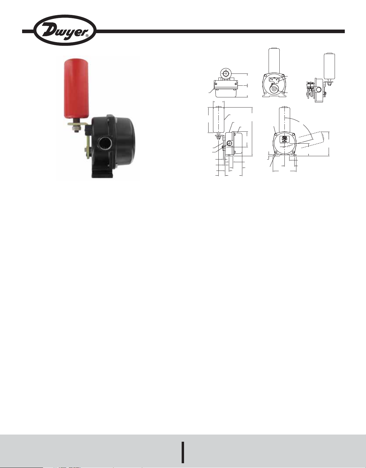
The Series CBAS is a rugged and reliable conveyor belt align-
ment switch. The compact die cast aluminum housing is designed for easy installation. The switch cover allows for simple
access to wiring terminals and CAM adjustments. Belt alignment
switches are typically used in pairs with one switch on each side
of the conveyor belt mounted near the first and/or last pulley of a
conveyor. Each series CBAS is equipped with two micro switches, allowing one actuation angle for small belt deviations and a
second actuation angle for extreme belt deviations. The actuation angles are factory set at 20 degrees and 35 degrees, each
actuation angle can be easily adjusted in the field to fit any application.
APPLICATIONS
• Conventional Belt Conveyors
• Ship Loading/Unloading Systems
• Stacker/Reclaim Conveyors
• Apron Feeder Conveyors
• Tripper or Shuttle Conveyors
• Crane, Shovel, or Drag Line Limit Switch
• Heavy Duty Limit Switch
INSULATORS
MICROSWITCHES
CAMS
INSIDE VIEW
2X 2-11/64
[55.17]
5-1/8
[130.18]
75°
2X 1-1/2
[38.1]
5-49/64
[70.25]
5-21/64
[135.33]
0-RING
5-9/16
[141.29]
LEVER
2X 3/4˝ NPT
3/16
[4.76]
1/4
[6.35]
51/64
[20.24]
ø2-3/8
[ø60.33]
1-15/32
[37.31]
TOUCH
PULLEY
1-63/64
[50.4]
3-43/64
[93.27]
CASE
2-9/16
[65.09]
2-9/16
[65.09]
10-9/16
[268.29]
COVER
3-11/32
[84.93]
29/32
[25.02]
2X 13/32 [10.32]
MOUNTING HOLES
COVER BOLTS
4X M10
9/32
[7.14]
SPECIFICATIONS
Temperature Limits: -4 to 140°F (-20 to 60°C).
Enclosure: Die cast aluminum.
Enclosure Rating: NEMA 6 (IP 67).
Switch Type: 2 SPDT.
Electrical Rating: 10 amp @ 125/250 VAC; 1/2 amp @ 125
VDC.
Electrical Connection: 3 screw type, common, normally open,
normally closed.
Electrical Conduit: Two 3/4" female NPT.
Activation Angles: 20 degrees and 35 degrees (adjustable).
Activation Force: 0.8 to 1.2 pounds.
Control Type: Automatic reset.
Weight: 6.4 pounds.
DWYER INSTRUMENTS, INC.
Phone: 219/879-8000 www.dwyer-inst.com
P.O. BOX 373 • MICHIGAN CITY, INDIANA 46361, U.S.A. Fax: 219/872-9057 e-mail: info@dwyer-inst.com
Page 2
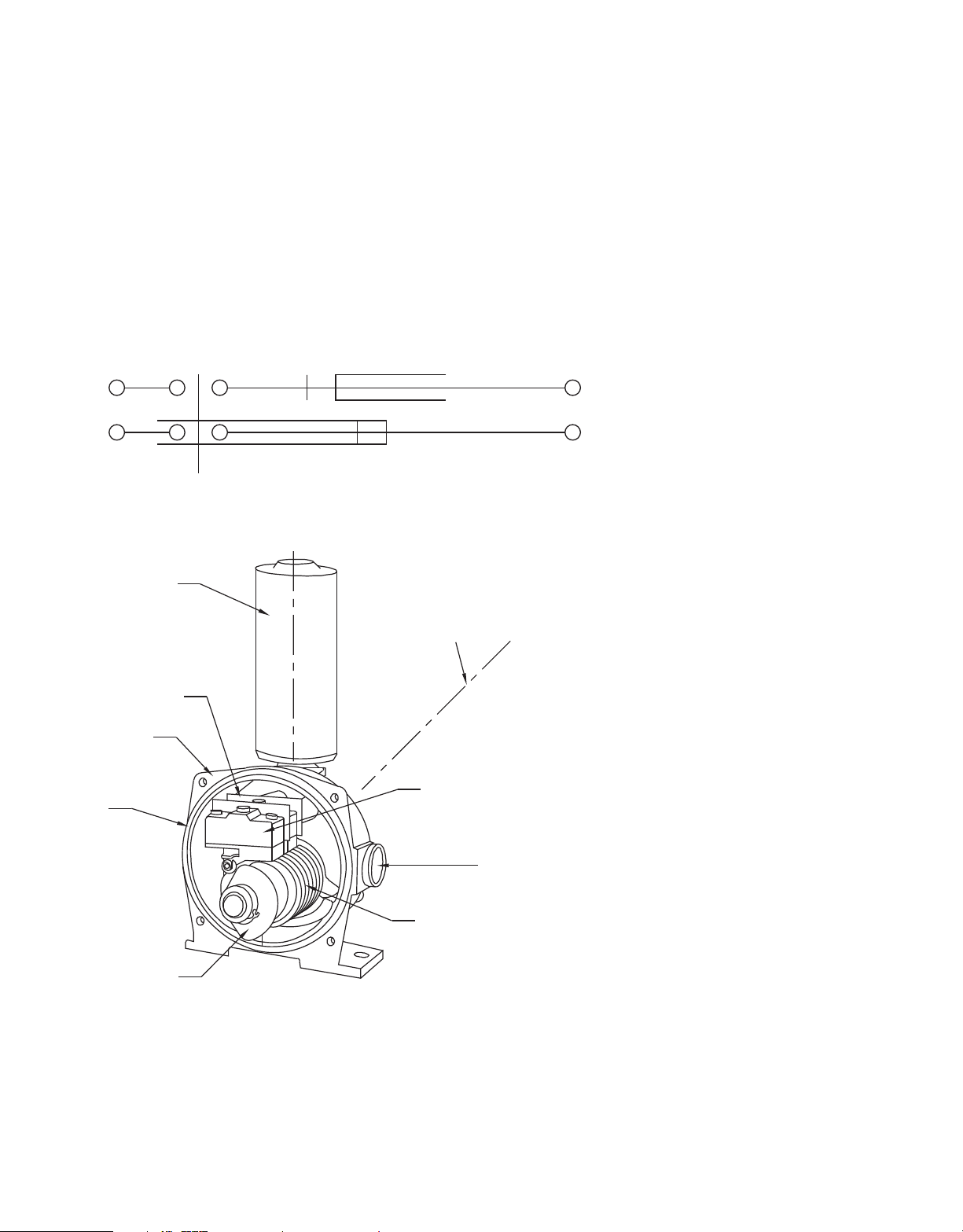
Operation Principle
The CBAS is typically installed in pairs on both sides of the belt
and positioned 1-6 feet from the head or tail pulley.
The touch roller is deflected by the deviation of the conveyor belt
from a vertical position to 75 degrees, and when the deviation is
restored, a spring will return the touch roller to the vertical
position when the belt is realigned. Cams are preset to turn on
or off the micro switches when the touch roller is deflected. When
the touch roller deviates 20 degrees the first micro switch will
change state, and when the touch roller is deviated 35 degrees
the second micro switch will change state.
Detection (Standard 1C X 2 Output)
TERMINAL NO. TERMINAL NO. TERMINAL NO.
0°
1
3
18˝ 20˝(ON)
2
5
4
* Switching frequency: 20 times/min.
• Number of contact: 1C x 2 output.
TOUCH ROLLER
INSULATING PLATES
CASING
PACKING
33°
35°(OFF)
MAX. SLANT ANGLE 75°
MICROSWITCHES
6
3/4˝ FNPT CONNECTION
CAMS
SPRING
Fig. 1 Construction of CBAS
Page 3

INSTALLATION
The mounting base should be fitted so that the CBAS touch roller
is 1-3 inches from the outside edge of the conveyor belt. The top
of the idler should be aligned 6.25” from the base of the CBAS.
A typical installations is shown in Fig. 2.
TOP OF IDLER
TOUCH ROLLER
6.25˝
MOUNTING BASE
CONVEYOR BELT
FRAME OF BELT CONVEYOR
IDLER
Fig. 2 Example of Installation of CBAS
Wiring
The Belt Alignment Switch has 2 SPDT relays that can be
accessed by removing the cover. The independent relays can be
used to control two separate circuits or allow a signal when there
is a slight belt shift and a server belt shift.
OPEN
20°
CLOSED
CLOSED
OPEN
35°
MICROSWITCH OPERATING POSITION
MICROSWITCH OPERATING POSITION
TOUCH ROLLER
MAXIMUM ANGLE
SHAFT
CAM
Fig. 3 Micro-switch Operating Positions
TOUCH ROLLER
Page 4

TERMINAL SCREW
ROLLER LEVEL
COM-1, 4
NO- 3, 6
NC- 2, 5
DEACTIVATEDACTIVATED
Fig. 4 Operation of Micro swtich
ADJUSTMENT
The Belt Sway Switch is adjusted to 20° and 35° at the factory.
If the angle of activation must be adjusted, the following steps
must be taken. Loosen the setscrew using an allen wrench as
shown in Fig 5 so that the cam can be moved. Rotate the cam to
the desired angle, and tighten the setscrew. Move the touch
roller to confirm that the micro switches activate at the desired
angle.
MAINTENANCE/REPAIR
Upon final installation of the Series CBAS, no routine
maintenance is required. The Series CBAS is not field
serviceable and should be returned if repair is needed. Field
repair should not be attempted and may void warranty.
WARRANTY/RETURN
Refer to “Terms and Conditions of Sales” in our catalog and on
our website. Contact customer service to receive a Return
Goods Authorization number before shipping the product back
for repair. Be sure to include a brief description of the problem
plus any additional application notes.
MULTISWITCH
TIGHTEN
ROTATE
Fig. 5 Adjustment of Cam
ALLEN WRENCH
LOOSEN
SET SCREW
CAM
©Copyright 2011 Dwyer Instruments, Inc. Printed in U.S.A. 3/11 FR# R4-443727-00 Rev. 1
DWYER INSTRUMENTS, INC.
Phone: 219/879-8000 www.dwyer-inst.com
P.O. BOX 373 • MICHIGAN CITY, INDIANA 46361, U.S.A. Fax: 219/872-9057 e-mail: info@dwyer-inst.com
 Loading...