

Page 1
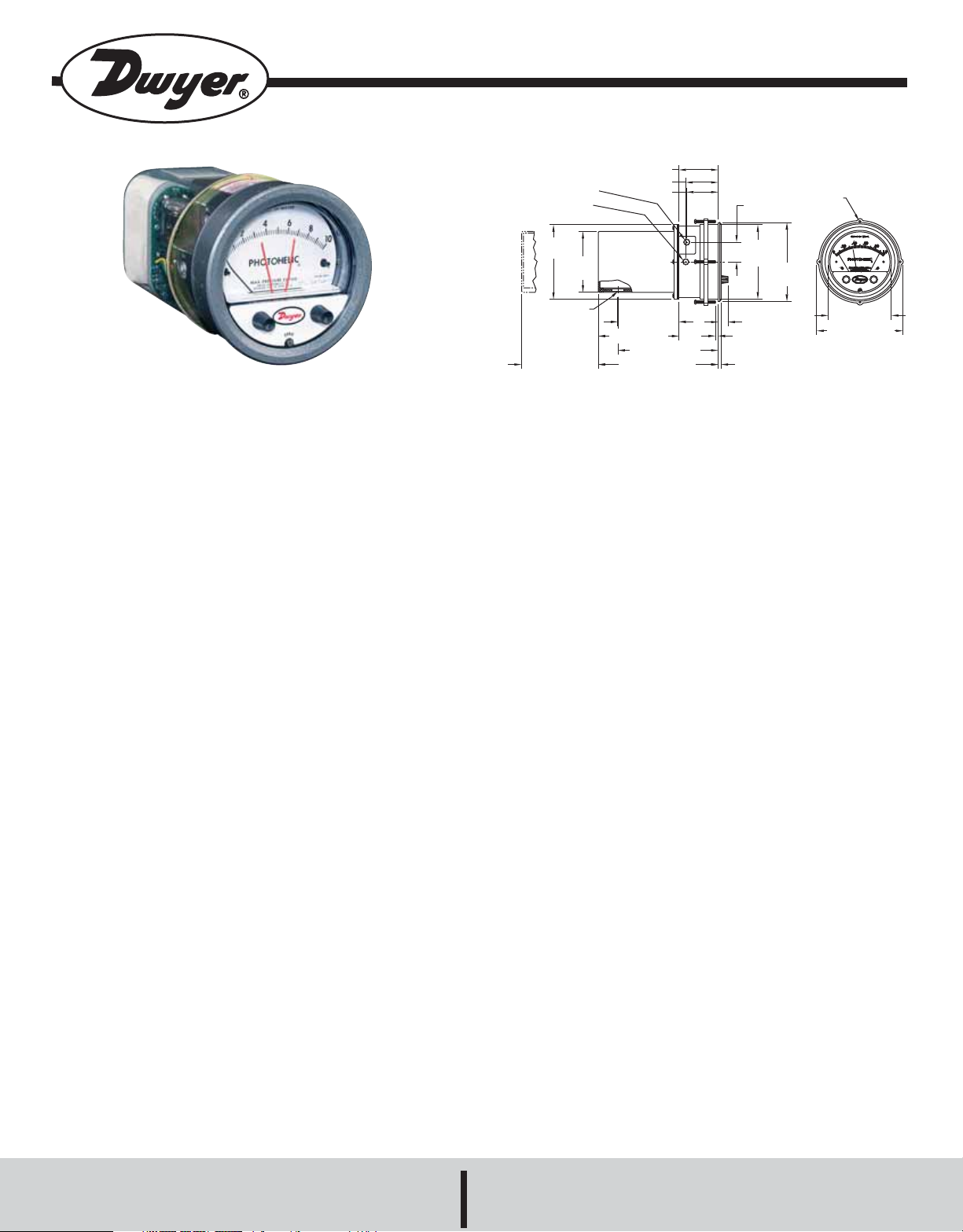
Series 3000 Photohelic®Pressure Switch/Gage
2-1/2 [63.50]
2-1/16 [52.39]
2 [50.80]
1-1/4
[31.75]
(4) 6-32 HOLES
EQUALLY SPACED ON
A 5-1/8 [130.18] B.C.
Ø4-47/64
[120.25]
Ø5
[127.00]
Ø4 [101.60]
FACE
5-1/2 [139.70]
O.D.
MOUNTING
RING
5/8 [15.88]
5/8 [15.88] PANEL
MAX
3/16 [4.76]
3-7/8 [98.43]
5-1/8 [130.18]
6-3/8 [161.93]
(7-5/8 [193.68])
4-3/8 [111.13]
HOUSING REMOVAL
3/4 CONDUIT
CONNECTION
Ø4-3/4
[120.65]
3-7/8 SQ
[98.43]
1/8 FEMALE NPT HIGH
PRESSURE CONNECTION
1/8 FEMALE NPT LOW
PRESSURE CONNECTION
Specifications - Installation and Operating Instructions
Fig. 1
Bulletin B-33
The Photohelic®Switch/Gage is a very versatile, precise pressure
switch combined with the time-proven Magnehelic®pressure gage.
Models are available with one or two phototransistor actuated relays.
Gage reading is unaffected by switch operation. Easy to adjust set points
have knob controls. Applied pressure and switch set points are fully
visible at all times. Deadband is one pointer width - less than 1% of full
scale. Double-pole double-throw relays can be easily interlocked to
provide variable deadband control. For positive, negative or differential
pressure only on 3600S models. Full scale ranges available from 0-.25
in w.c. to 0-6000 psig.
PHOTOHELIC®GAGE SENSING - HOW IT WORKS
In a typical control application, the Photohelic®switch/gage controls
between high and low pressure set points. When pressure changes,
reaching either set point pressure, the beam from an LED to the limiting
phototransistor will be cut off by the helix-driven light shield. The
resulting signal change is electronically amplified to actuate its DPDT
slave relay and switching occurs. Dead band between make and break
is 1% of full scale or less - just enough to assure positive, chatter-free
operation.
SPECIFICATIONS
GAGE SPECIFICATIONS
Service: Air and non-combustible, compatible gases.
Wetted Materials: Consult factory.
Accuracy: ±2% of full scale at 70°F (21.1°C). ±3% on -0 and ±4% on
-00 models.
Pressure Limits: -20˝ Hg. to 25 psig (-0.677 to 1.72 bar). MP option;
35 psig (2.41 bar), HP option; 80 psig (5.52 bar). 36003S – 36010S;
150 psig (10.34 bar). 36020S and higher; 1.2 x full scale pressure.
Temperature Limits: 20 to 120°F (-6.67 to 48.9°C); Low temperature
option available.
Process Connections: 1/8˝ female NPT.
Size: 4˝ (101.6 mm) dial face, 5˝ (127 mm) O.D. x 8-1/4˝ (209.55 mm).
Weight: 4 lb (1.81 kg).
SWITCH SPECIFICATIONS
Switch Type: Each setpoint has 2 Form C relays (DPDT).
Repeatability: ±1% of full scale.
Electrical Rating: 10A @ 28 VDC, 10A @ 120, 240 VAC.
Electrical Connections: Screw terminals.
Power Requirements: 120 VAC, 50/60 Hz; 240 VAC & 24 VAC;
Power optional.
Mounting Orientation: Diaphragm in vertical position. Consult factory
for other position orientations.
Set Point Adjustment: Adjustable knobs on face.
DWYER INSTRUMENTS, INC.
P.O. BOX 373 • MICHIGAN CITY, INDIANA 46361, U.S.A. Fax: 219/872-9057 e-mail: info@dwyer-inst.com
Phone: 219/879-8000 www.dwyer-inst.com
Page 2
Bulletin B-33
SNAP RING GROOVE
4-13/16˝ (122 mm)
DIA. HOLE REQUIRED
FOR PANEL MOUNTING
1/8˝ MALE NPT PRESSURE CONNECTIONS.
SINGLE HIGH PRESSURE CONNECTION
FOR SERIES 36000A MODELS.
page 2
INSTALLATION
1. Location
All parts of the Dwyer®Photohelic®pressure switch/gage are ruggedly
constructed and will stand a moderate amount of vibration, physical
shock, and handling. Normal care in handling and installation is all that
is required. In cases where instrument panel vibration is severe, the
panel should be a spring mounted or the amplifier-relay unit mounted
remotely on a more stable surface.
Select a location where the ambient temperature will not exceed 120°F.
Pneumatic pressure sensing lines may be run any necessary distance.
For example, 250 foot sensing lines will not affect accuracy but will damp
the reading slightly. Do not restrict lines. If pulsating pressure or vibration
causes excessive pointer oscillation or relay chatter, consult factory for
additional damping means.
2. Position
The Photohelic
®
Pressure Switch/Gage may be mounted as an integral
package or the amplifier-load relay assembly and housing may be
mounted remotely from the indicating gage-phototransistor unit.
Extension cords with 7 pin plugs and receptacles are available from
Dwyer for interconnection of the two units.
The unit may be mounted in any desired position, scale vertical or
horizontal, without affecting its accuracy, but must be rezeroed if position
is changed from horizontal to vertical or vice versa. The -0 and -00
models must be mounted with the scale vertical.
3. Mounting
The Photohelic
®
Switch/Gage is normally mounted before making
electrical connections, as the electrical enclosure is independent of the
mounting means and may be removed at any time.
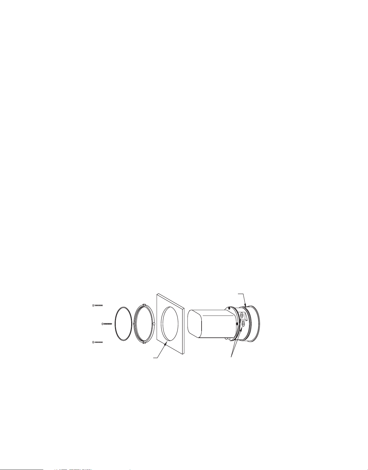
Panel Mounting
Normal mounting is flush or through panel is shown in Fig. 2. Be sure to
allow 4-3/8˝ extra space behind the unit for electrical enclosure removal.
Make a single 4-13/16˝ diameter hole in the panel. Insert the entire
Photohelic®Switch/Gage unit from the front, then slip on the mounting
ring and snap ring from the rear. Seat the snap ring in its groove, back
up the mounting ring against snap ring and tighten the four (4) 2˝ No. 632 clamp screws provided. If behind panel space is critical, the amplifierrelay unit can be mounted remotely. See the Remote-Relay Mounting
Instructions for details.
Through Panel Mounting
Fig. 2
Page 3
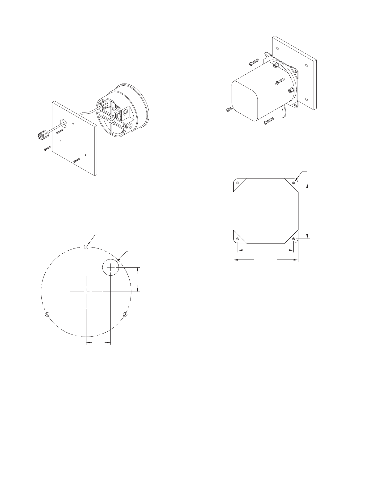
Gage Mounting with Relays Remote
4-9/32
[108.74]
5
[127.00] SQ
4-9/32
[108.74]
Ø3/16
TYP 4 PLACES
1-1/8
[28.58]
1-1/8
[28.58]
THREE 3/16 DIA.
HOLES AT 120°
SURFACE MTG.
3/4 DIA. HOLE
FOR WIRE CONN.
Where it is desirable to mount the amplifier-relay unit separate from the
gage-phototransistor unit, the gage may be mounted either as shown in
Fig. 2 (except less amplifier-relay portion) or surface mounted as shown
in Fig. 3A. Use the layout shown in Fig. 3B to locate holes. The complete
package cannot be surface mounted.
Surface Mounting
Fig. 3A
Bulletin B-33
page 3
Remote Amplifier-Relay Unit
Fig. 4A
Hole Layout
Hole Layout (Front)
Fig. 3B
Remote Relays Mounting
The amplifier - relay unit may be mounted remotely as shown in Fig. 4A.
Use the hole layout as shown in Fig. 4B for this option.
Additional mounting information for special requirements is available
from the factory.
Fig. 4B
4. Pneumatic Connections & Zeroing
After installation but before making pressure connections, set the
indicating pointer exactly on the zero mark, using the zero adjust screw
located at the bottom of the front cover. Note that this adjustment can
only be made with the high and low pressure taps both open to
atmosphere.
Connect the high and low pressure taps to positive, negative, or
differential pressure sensing points. Use 1/4˝ diameter metal or other
instrument tubing and 1/8˝ NPT adaptors at the Dwyer
®
. Photohelic
pressure/switch gage. Adaptors for rubber or soft plastic tubing are
furnished with the instrument for use where this type of connection is
preferred.
®
If the Photohelic
one of the pressure taps must be left open to atmosphere. This will allow
the reference pressure to enter. In this case, installation of a Dwyer
Switch/Gage is not used to sense differential pressure,
®
. No.
A-331 Filter Plug or similar fitting in the reference pressure tap is
recommended to reduce the possibility of dust entering the instrument.
®
®
Note: If the Photohelic
switch/gage is over pressured, pointer may
‘jump” from full scale back to zero and remain there until the excess
pressure condition is relieved. Users should be aware of possible false
zero pressure indications under this conditions.
Page 4
Bulletin B-33
4-3/8 [111.13]
COVER MOUNTING SCREWS
SUPPORT CONDUIT
FROM PANEL
COVER PULL
OUT
FLEXIBLE CONDUIT
SECTION B SECTION C
SECTION A
SECTION D
SECTION E
CIRCUIT:
POWER SUPPLY:
CONTACT RATING:
page 4
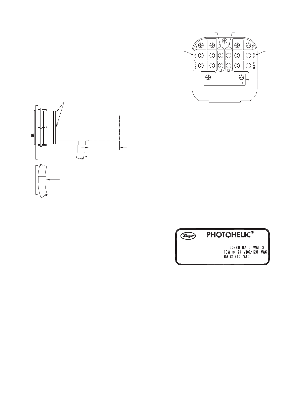
ELECTRICAL CONNECTIONS
1. Cover
The amplifier-relay unit has an easy to remove housing. Remove the
three (3) screws as shown in Fig. 5 and slide the housing off. Make all
the electrical connections before reinstalling and refastening the
housing.
2. Conduit
Electrical access to the connection box portion of the relay housing is by
bottom opening for 3/4˝ conduit. Use of flexible conduit is recommended.
It should be supported from the panel or other suitable surface to prevent
the wiring system from exerting undue strain on the instrument. See Fig.
5.
Mounting Details
Terminal Board
CAUTION: Do not apply electrical
current to terminals in sections B and C.
Fig. 6
Separate Ground Wire attachment is provided for by a No. 6-32 screw
on the mounting bracket near the conduit opening. An additional ground
wire connection is located on the side of the gage body for use when the
amplifier-relay unit is mounted remotely.
Single Set-Point instruments are furnished with the right or high setpoint components and circuitry in place. These are connected to
Sections A and B of the terminal board. The left or low set-point
components are omitted.
Fig. 5
3. Terminal or Connection Board Layout
In Fig. 6,”Terminal Board”, Section A contains the connections for the
load or slave relay actuated by the high or right set-point. This relay is a
double pole, double throw type. The two top connections are normally
closed, the two middle connections are normally open, and the bottom
connections are the common pair. The relay is in its normal or DeEnergized position when pressure is below the right hand set-point.
Section D is exactly the same as Section A except that its load or slave
relay is controlled by the low or left set-point. The De-Energized position
is below the left hand pointer set-point.
Section B contains the external connections to the holding coil circuit for
the high or right set-point relay and Section C contains similar
connections for the low or left set-point relay. The function and use of
these connections varies somewhat depending on the circuit style of the
instrument. See paragraphs 5 and 6 for details.
Section E contains the power connections for the control unit
transformer primary. The transformer in turn supplies reduced voltage
power for the LED, phototransistor, amplifier unit, and load relay pull in
and holding coils. Connections must always be made to this section in
order to put the unit in operation. Standard units are designed for 117
VAC input to the transformer. Special units are also available for other
voltages.
4. Circuit Style
The Photohelic
®
Switch/Gage is available with several factory installed
optional internal circuits. They are identified as to style by a label shown
in Fig. 7. This label is mounted prominently on the terminal board of each
instrument. The letter H denotes a circuit in which the relay can be made
to latch or remain energized after pressure increase to its set-point.
Circuit Label
Fig. 7
The letter “L” denotes a circuit in which the relay can be made to latch or
remain de-energized after pressure decrease to its set-point. Two letters
are required to fully identify a dual set-point unit. Thus, circuit style HH,
which is standard, is a dual set-point circuit which has provisions for
latching on pressure increase to either set-point. Single relay units are
identified by the letters “SR” followed by “H” for the standard unit or “L”
for the special low latch unit. Units for use with other than standard 117
VAC will be so indicated on the label.
Page 5

RESET
RESET
Bulletin B-33
117 VOLT LINE
RESET JUMPERS
1/6 HP*
117 VOLT
LOAD
page 5
5. Dual Set Point Automatic Reset
Circuit Style HH is used for simple on-off switching applications. To place
in service, connect load circuits to the appropriate terminals in Section A
(Fig. 6) for the right set-point and Section D for the left set-point. Note the
the N.O. contacts are open when the gage pressure pointer is to the left
of the set-point pointers. No connections are necessary in Section B and
C. Make external ground connections as required and connect power to
Section E for the control unit. To use circuit style LL for automatic reset,
a jumper wire must be installed between the upper and lower terminals
in sections B and/or C.
6. Dual Set Point Manual Reset
Circuit Style HH may also be used for manual reset applications where it
is desired to have maintained contact on either relay following pressure
increase above its set-point. Load or signal connections are made to the
appropriate terminals in Sections A and D (as in paragraph above).
Connect terminals in Sections B and C through normally closed switches
or push buttons as shown in Fig. 8. Use of “dry-circuit” type switches
such as Dwyer Part No. A-601 with palladium, gold, etc. or rotary wiping
action type contacts is recommended. Make external ground
connections as required and connect power to Section E for the control
unit.
Circuit style LL is used for manual reset applications which require that
contact be maintained following pressure decrease below the set-point.
Load connections are made to the appropriate terminals in Sections A
and D. A normally open type manual reset switch such as Dwyer Part No.
A-601 is connected to the terminals in sections B and C. The circuit must
be “armed” by momentarily closing the switch while the black pointer is
to the right of the set-point. From that point on, the circuit will latch on
pressure decrease below the set-point and remain latched on pressure
increase until manually reset with the optional switch.
9. Dual Set-Point Special Purpose Circuits
Circuit Style LL may be used where manual reset following maintained
contact on pressure decrease to either set-point is desired. Circuit Styles
HL and LH are combination units. For special combinations of features,
special units, and detailed instructions regarding their use, consult
factory.
®
10. Single Set-Point Photohelic
Switch/Gage
The single set-point Photohelic®Switch/Gage is furnished with the right
set-point only. Terminals in Section A and B (Fig. 6) are connected to this
relay. Circuit Style SRH is wired or automatic reset as in paragraph 5.
Manual reset is accomplished by adding a normally closed reset switch
or push button to the circuit as described in paragraph 6.
11. Single Set-Point Special
Manual reset after actuation on falling pressure can be obtained by using
Circuit Style SRL. Consult the factory for special units and detailed
instructions regarding their use.
12. Placing in Service
In normal operation each relay is de-energized when the pressure
applied to the instrument is below its set-point. Special low-latching units
will ordinarily have to be reset before placing on the line in normal
operation.
High-Low Limit Control (Circuit HH)
Manual Reset with Circuit HH
CAUTION: Do not apply electrical
current to terminals in sections B and C.
Fig. 8
7. Dual Set Point Automatic and Manual Reset Combinations
Circuit style HH may be used with either set-point wired and operating as
in paragraph 5 and other set-point wired and operating as in paragraph
6.
8. High Low Limit Control - Dual Set-Point
Circuit style HH may be used to control fans, dampers, pumps, etc.
between the set-points of a Photohelic
®
Switch/Gage. To accomplish this,
use one set-point relay to reset the other as shown in the wiring diagram
Fig. 9. In this typical application, the load (for instance a fan) would be
connected to the N.C. contacts of the right set-point relay, Section A (Fig.
6)/ On pressure rise to the right set-point, its relay would pull in and hold
even though pressure might then fall below that set-point, its relay would
automatically be De-Energized, return to its normal position and in so
doing, open the holding coil circuit from Section B (Fig. 6). The right setpoint relay would thus be reset and the cycle could repeat.
*Note: For larger motors, use the Photohelic® in a maintained contact,
117 Volt Control or Push Button Circuit of the motor starter.
Fig. 9
13. Failure Mode
The Photohelic®Switch/Gage circuit design provides certain protection in
the event of a loss of pressure or electrical power. In either case, both
relays will de-energize, returning to their normal “zero pressure” state.
The exceptions to this are models with center zero ranges. Because the
relays on all standard models are always energized when the indicating
(black) pointer is to the right of their respective set points, the relay action
on loss of pressure will depend on set-point position, since either of them
could be located to the left of zero. As an example; if the left pointer were
set at -2 in. w.c. and negative pressure was -3 in. w.c., a loss of that
pressure would allow the black pointer to return to the center and thus
cause the low set-point relay to energize.
MAINTENANCE
Photohelic
®
Switch/Gages are precision instruments, expertly assembled
and calibrated at the factory. They require no lubrication or periodic
servicing. If the interior is protected from dust, dirt corrosive gases and
fluids, years of trouble-free service may be expected. Zero adjustment
should be checked and reset occasionally to maintain accuracy. Any
repairs necessary to either the Magnehelic® pressure gage or the
electronic components should be performed by a trained instrument
mechanic. In most cases, this is best accomplished by returning the
complete Photohelic
®
Switch/Gage to the Dwyer Instruments, Inc.
factory.
Page 6

Bulletin B-33
page 6
PHOTOHELIC®PRESSURE SWITCH/GAGE
MODEL AND RANGES
Range,
Inches
of
Model
3000-00
3000-0
3001
3002
3003
3004
3005
3006
3008
3010
3015
3020
3025
3030
3040
3050
3060
3080
3100
3150
*Note: The Photohelic
specifications for the acceptance of unlisted components.
Water
0-.25
0-.50
0-1.0
0-2.0
0-3.0
0-4.0
0-5.0
0-6.0
0-8.0
0-10
0-15
0-20
0-25
0-30
0-40
0-50
0-60
0-80
0-100
0-150
Minor
Div.
.005
.01
.02
.05
.10
.10
.10
.20
.20
.20
.50
.50
.50
1.0
1.0
1.0
2.0
2.0
2.0
5.0
Model
3300-0
3301
3302
3304
3310
3320
3330
Model
3201
3202
3203
3204
3205
3210
3215
3220
3230
36003S
36006S
36010S
36020S
36030S
36060S
36100S
36300S
36600S
®
pressure switch/gage may be used in an Under Writers Laboratories approved industrial control panel if the usage conforms to UL
Range,
Zero
Center
Inches
of Water
.25-0-.25
.5-0-.5
1-0-1
2-0-2
5-0-5
10-0-10
15-0-15
Range
PSIG
0-1
0-2
0-3
0-4
0-5
0-10
0-15
0-20
0-30
0-30
0-60
0-100
0-200
0-300
0-600
0-1000
0-3000
0-6000
Minor
Div.
.01
.02
.05
.10
.20
.50
1.0
Minor
Div.
PSIG
.02
.05
.10
.10
.10
.20
.50
.50
1.0
1.0
2.0
2.0
5.0
10
20
20
100
200
Dual Scale Air Velocity Units
(for use with pitot tube)
Range, Air
Velocity
FPM
300-2000
500-2800
500-4000
1000-5600
2000-12500
Minor Div.
MM
.20
.50
.50
1.0
2.0
2.0
Minor
Div.
MM
.50
Model
3000-00AV
3000-0AV
3001-AV
3002-AV
3010-AV
Model
3000-6MM
3000-10MM
3000-25MM
3000-50MM
3000-80MM
3000-100MM
Model
3300-20MM
Ranges,
Inches of
Water
0-.25
0-50
0-1.0
0-2.0
0-10
Range,
MM of
Water
0-6
0-10
0-25
0-50
0-80
0-100
Range,
Zero
Center
MM of
Water
10-0-10
Model
3000-15CM
3000-20CM
3000-25CM
3000-50CM
3000-80CM
3000-100CM
3000-150CM
3000-200CM
3000-250CM
3000-300CM
Model
3300-4CM
3300-10CM
3300-30CM
Model
3000-60Pa
3000-125Pa
3000-250Pa
3000-500Pa
3000-750Pa
Range
CM of
Water
0-15
0-20
0-25
0-50
0-80
0-100
0-150
0-200
0-250
0-300
Range,
Zero
Center
Cm of
Water
2-0-2
5-0-5
15-0-15
Range,
Pascals
0-60
0-125
0-250
0-500
0-750
Minor
Div.
CM
.50
.50
.50
1.0
2.0
2.0
5.0
5.0
5.0
10.0
Minor
Div.
CM
.10
.20
1.0
Minor
Div.
Pascals
2.0
5.0
5.0
10.0
25.0
Model
3300-250Pa
3300-500Pa
Model
3000-1kPa
3000-1.5kPa
3000-2kPa
3000-3kPa
3000-4kPa
3000-5kPa
3000-8kPa
3000-10kPa
3000-15kPa
3000-20kPa
3000-25kPa
3000-30kPa
Model
3300-1kPa
3300-3kPa
Range,
Zero
Center
Pascals
125-0-125
250-0-250
Range
KiloPascals
0-1.0
0-1.5
0-2.0
0-3.0
0-4.0
0-5.0
0-8.0
0-10
0-15
0-20
0-25
0-30
Range,
Zero
Center
Kilopascals
.5-0-.5
1.5-0-1.5
Minor Div.
Pascals
125-0-125
250-0-250
Minor Div.
KiloPascals
.02
.05
.05
.10
.10
.10
.20
.20
.50
.50
.50
1.0
Minor
Div.
Kilopascals
.02
.10
DWYER INSTRUMENTS, INC.
Phone: 219/879-8000 www.dwyer-inst.com
P.O. BOX 373 • MICHIGAN CITY, INDIANA 46361, U.S.A. Fax: 219/872-9057 e-mail: info@dwyer-inst.com
Page 7

Boletín B-33
2-1/2 [63.50]
2-1/16 [52.39]
2 [50.80]
1-1/4
[31.75]
(4) 6-32 HOLES
EQUALLY SPACED ON
A 5-1/8 [130.18] B.C.
Ø4-47/64
[120.25]
Ø5
[127.00]
Ø4 [101.60]
FAC E
5-1/2 [139.70]
O.D.
MOUNTING
RING
5/8 [15.88]
5/8 [15.88] PANEL
MAX
3/16 [4.76]
3-7/8 [98.43]
5-1/8 [130.18]
6-3/8 [161.93]
(7-5/8 [193.68])
4-3/8 [111.13]
HOUSING REMOVAL
3/4 CONDUIT
CONNECTION
Ø4-3/4
[120.65]
3-7/8 SQ
[98.43]
1/8 FEMALE NPT HIGH
PRESSURE CONNECTION
1/8 FEMALE NPT LOW
PRESSURE CONNECTION
El Interruptor/Indicador de Presión Photohelic®Serie 3000
INSTRUCCIONES Y OPERACION
El Interruptor/Indicador de Presión Photohelic®es un an interruptor
de presión muy versátile y preciso, combinado con el indicador de
presión de respuesta rápida Magnehelic®. Los modelos están
disponibles con uno o dos fototransistores que actúan sobre relés. A la
lectura del indicador no le afecta la operación del interruptor. Facilidad
de ajuste del punto de trabajo mediante botones de control. Las presión
aplicada y los puntos do interrupción (disparos) son claramente visibles
en todo momento. La banda muerta tiene una anchura de menos del
1% del fondo de escala. Los relés de doble circuito, doble disparo
pueden ser facilmente entrelazados para proporcionar un control
variable de la banda muerta. Para presión positiva, negativa y
diferencial; para models de un sólo relé, presión positiva sólo en modelo
36000S. Rangos de fondo escala disponibles de 0 - 0.25” c.a. a 0 - 6000
psig.
SENTIDO DEL PHOTOHELIC®SU FUNCIONAMIENTO
En una applicación de control tipica, el interruptor/indicador Photohelic
controla entre los puntos de trabajo de alta y baja presión. Cuando la
presión cambia, alcanzando cualquier presión del punto de trabajo, el
haz de lud de un LED dirigido hacia el fototransistor limitador será
interrumpido por el escudo de luz del eje helicoidal. El cambio de la
señal resultante es electronicamente amplificada para actuar sobre su
relé esclavo DPDT y ocasiona el disparo del interruptor. La banda
muerta entre lo marcado y el corte es del 1% del fondo de escala o
menor. Suficiente para asegurar una operación positiva y libre de
errores.
*
Figura 1
ESPECIFICACIONES
GAGE SPECIFICATIONS
Service: Air and non-combustible, compatible gases.
Wetted Materials: Consult factory.
Accuracy: ±2% of full scale at 70°F (21.1°C). ±3% on -0 and ±4% on -
00 models.
Pressure Limits: -20" Hg. to 25 psig (-0.677 to 1.72 bar). MP option;
35 psig (2.41 bar), HP option; 80 psig (5.52 bar). 36003S – 36010S;
150 psig (10.34 bar). 36020S and higher; 1.2 x full scale pressure.
Temperature Limits: 20 to 120°F.
(-6.67 to 48.9°C) Low temperature option available.
Process Connections: 1/8˝ female NPT.
Size: 4˝ (101.6 mm) dial face, 5˝ (127 mm) O.D. x 8-1/4˝ (209.55 mm).
Weight: 4 lb (1.81 kg).
SWITCH SPECIFICATIONS
®
Switch Type: Each setpoint has 2 Form C relays (DPDT).
Repeatability: ±1% of full scale.
Electrical Rating: 10A @ 28 VDC, 10A @ 120, 240 VAC.
Electrical Connections: Screw terminals.
Power Requirements: 120 VAC, 50/60 Hz; 240 VAC & 24 VAC Power
optional.
Mounting Orientation: Diaphragm in vertical position. Consult factory
for other position orientations.
Set Point Adjustment: Adjustable knobs on face.
Page 8

Ranura Del Anillo De Suceccion
Tapones De Presion
Neumatica
Ø4-13/16 [122.24]
Dianetroaguiero
Boletín B-33
P. 2
INSTALACION
Localización: Todas las partes del interruptor/indicador Photohelic®de
Dwyer®están robustamente construidas para soportar una moderada
cantidad de vibración, impacto físico y manejo del mismo. Un cuidado
normal en su manejo e instalación es todo lo que se precisa. En los
casos en los que la vibración del panel de instrumentos sea intensa, éste
deberá estar montado sobre algún resorte, o bien, la unidad del reléamplificador estar montada en una superficie más estable.
Elegir un lugar donde la temperatura ambiente no exceda de 120°F
(49°C).
Las lineas sensoras de presión neumática deben alargarse a la distancia
que sea necesaria. Por ejemplo, 250 pies (75 m) de lineas sensoras no
afectarán a la precisión, pero amortiguarán la lectura ligeramente. Si la
presión pulsante o la vibración dan lugar a un punto de excesiva
oscilación o el relé castañea, consultar con la fábrica para medios
adicionales de amortiguamiento. Ver accesorios adecuados con el
Boletín S-101.
Pocisión: El Photohelic®debe ser montado como un conjunto
compacto, o bien el modulo rele carga-amplificador ensamblado y su
carcasa se monta en un lugar remoto de la unidad indicadorfototransistor. Los cables de extgension con conexion de 7 pies y los
conectores están disponibles en Dwyer para interconectar las dos
unidades.
Montaje: El Photohelic®se monta normalmente antes de hacer las
conexiones eléctricas, por lo tanto la carcasa eléctrica es independiente
de la forma me montaje y puede ser quitada en cualquier momento.
Montaje en Panel: El montaje normal es embutir o atravesar el panel
como muestra la Fig. 2. Asegúrase de que deja un espacio extra de 43/8” (111 mm) detrás de la unidad; quitar la carcasa eléctrica. Hacer un
simple agujero de 4 13/16˝ (122 mm) de diametro en el panel. Inserter
todo el Photohelic®por el frontal del panel, luego deslizar el anillo de
sujección y encajar el anillo por la parte de atrás. Coloque el anillo de
sujección en su ranura, mueva hacia atrás el anillo de sujección y una
vez más encaje el anillo y apriete los cuatro (4) tornillos de abrazadera
de 2˝ (50 mm) No. 6-32 que se suministran. Si el espacio detrás del
panel es crítico, la unidad relé-amplificador se puede montar de forma
remota. Ver Instrucciones de Mantaje de Relé Remoto para más
detalles.
La unidad puede estar montada en la posición que se
desee, la escala vertical u horizontal, sin que ello afecta a la precisión,
pero debe ser recalibrado el cero si la posición cambia de horizontal a
vertical o viceversa. Los models - 0 y - 00 deben estar montados con la
escala vertical.
Atraves del Panel de Montaje
Figura 2
Page 9

Montaje del Indicador con los Relés Remotos: Donde se desee
1-1/8
[28.58]
1-1/8
[28.58]
Tiesogujeros De Ø3/16 [4.76] Diam.
Separados 120° en la
superjiciede montaje
Agujerode 3/4" [19.05] de diam.
para conexion del cableado
4-9/32
[108.74]
5
[127.00] SQ
4-9/32
[108.74]
Ø3/16
TYP 4 PLACES
montar la unidad relé-amplificador separada de la unidad
indicador/fototransistor, el indicador puede montarse de cualquiera de
las maneras mostra-das en la Fig. 2 (excepto la parte del reléamplificador) o montarse sobre superficie como se muestra en la Fig 3A.
Utilice el trazado monstrado en la Fig. 3B para localizer los agujeros. El
conjunto completo no se puede montar sobre superficie.
Boletín B-33
P. 3
Figura 3A
Montaje Sobresuperficie
Figura 3B
Esquema del Agujero (de frente)
Unidad Relé-Amplificador Remota
Figura 4A
Figura 4B
Esquema de los Agujeros
Conecte las espitas de alta y baja presión a los puntos de presión
positiva, negativa o diferencial. Utilice tubo metálico de 4” NPT (3.175
mm) del interruptor/indicador de presión Photohelic®de Dwyer®. Los
adaptores para tubos de caucho o de plástico blando son
proporcionados con el instrumento para utilizarlos cuando se prefiera
este tipo de conexión.
Montaje Remoto de los Relés: La unidad relé-amplificador puede
montarse remotamente como se muestra en la Fig. 4A. Ulice el trazado
de agujeros que se muestra en la Fig. 4B para esta opcion. Para mas
información sobre el montaje para requerimientos especiales, consulte
con la fabrica.
Conexiones Neumaticas y Ajuste del Cero: Después de la
instalación, pero antes de hacer las conexiones de presión, coloque el
puntero de indicación (la aguja) exactamente sobre la marca del cero,
usando el tornillo de ajuste del cero situado en la parte de abajo de la
cubierta frontal. Tenga en cuenta que este ajuste sólo se pueda hacer
con las espitas de alta y baja presión abiertas a la atmósfera.
Si el Photohelic®no se usa para detectar presión diferencial, una de las
espitas de presión debe abierta a la atmósfera. Esto permitirá la entrada
de la presión de referencia. En este caso, se recomienda la instalación
de un filtro de Dwyer®No. A-331 u otro similar apropiado en la espita de
la presión de referencia para reducir la posibilidad de entrada de polvo
en el instrumento.
Nota: Si el interruptor/indicador Photohelic®está sobre-presionado, el
puntero (aguja) “salta” desde el final de la escala hasta el cero y se
mantiene ahí hasta que la condición de exceso de presión se alivia. Los
usuarios deberían ser consecuentes de las posible indicaciones de falso
cero bajo esta condición.
Page 10

Boletín B-33
4-3/8 [111.13]
Tornillos De Montaje De La Cubierta
Soporte Del Conducto
Del Panel
Espacio Para
Sacar La Cubierta
Conducto Flexible
Seccion B Seccion C
Seccion A
Seccion D
Seccion E
TIPO DE CIRCUITO:
TENSION DE ALLMENTACION:
RANGO DE CONTACTO:
P. 4
CONEXIONES ELECTRICAS
1. Cubierta: La unidad relé-amplificador tiene una carcasa fácil de
quitar. Quite los tres (3) tornillos como se muestra en la Fig. 5 y deslice
hacia afuera la carcasa. Haga todas las conexiones eléctircas antes de
reinstaler y reasegurar la carcasa.
2. Conducto: El acceso eléctrico a la parte de la carcasa del relé de la
caja de conexión se hace abriendo un tapón para conductos de (19 mm).
Se recomienda el uso de conductos flexibles. Este se sujetaría al panel
u otra superficie apta para prevenir el sistema de cableado de un
esfuerso de tensión indebido en el instrumento. Ver Fig. 5.
3. Esquema del Terminal o Placa de Conexión: En la Fig. 6, “Placa
de Terminales,” la Seccion A contiene las conexiones para al relé de
carga o esclavo actuado por el punto de trabajo derecho o de alta. Este
relé es de tipo doble polo, de doble circuito. Las dos conexiones
superiores son normalmente carradas, las dos del medio son
normalmente abiertas y las dos de abajo son el común. El relé está en
su posición normal o des-energizado cuando la presión está por debajo
del punto de trabejo del lado derecho (del alta).
La Seccion D es exactamente igual que la Seccion A, excepto que su
relé de carga o esclavo está controlado por el punto de trabajo izquierdo
o de baja. La posición
des-energizada está pro debajo del punto de trabajo del lado izquierdo
(de baja).
La Seccion B contiene las conexiones externas para el mantenimiento
del circuito bobinado para relé del punto de trabajo derecho o de alta y
la Seccion C, contiene conexiones similares para el relé del punto de
trabajo izquierdo o de baja. La función y uso de estas conexiones varía
algo dependiendo del tipo de circuito del instrumento. Ver párrafos 5 y
6 para más detalles.
La Seccion E contiene las conexiones de alimentación para el
transformador primario de la unidad de control. El transformador a
cambio suministra un reducido voltaje de alimentación para el LED, el
fototransistor, la unidad amplificadora y tirar del relé descarga y
mantener el bobinado. Las unidades estánder están diseñadas para 117
VCA de entrada al transformador. También están disponibles unidades
especiales para otros voltajes.
Está provisto de una atadura para Cable Separado a Tierra mediante
un tornillo No. 6-32 en la repisa montada carca de la abertura del
conducto. Está localizado un cable adicional a tierra en el lateral del
cuerpo de indicación para usa lo cuando la unidad relé-amplificador está
montada remotamente.
Los instrumentos de un Punto de Trabajo se suministran con los
componentes del punto de trabajo de alta o derecho y la circuitería
correspondiente. Esta está conectada a las Secciones A y B de la placa
de terminales. Los componentes del punto de trabajo izquierdo o de
baja están omitidos.
4. Tipo de Circuito: El Photohelic®está disponible con varios circuitos
internos opcionales instalados en fábrica. Están identificados como tipo
por una etiqueta mostrada en la Fig. 7. Esta ertiqueta se monta de forma
prominente en la placa de terminal de cada instrumento. La letra H
indica un circuito cuyo relé puede pasar a almacenar un estado eléctrico
o retenerse energizado (activado) después de que la presión sobrepase
or un incremento su punto de trabajo.
La letra L indica un circuito en el cual el relé pueda pasar a almancer un
estado eléctrico o retenerse des-energizado después de que la presión
sobrepase por decremento su punto de trabajo. Se necesitan dos letras
para indentificar completamente una unidad de doble punto de trabajo.
Así, el ecicuito de tipo HH, el cual es el estándar, es un circuito de doble
punto de trabajo, el cual está provisto para el almacenamiento do
estados de corriente (latching) cuando ambos puntos de trabajo son
sobrepasados por un incremento de la presión. Las unidadas de un sólo
relé están identificadas por las retras SR seguidas de una H para la
unidad estánder o por una L para unidades especiales de
almacenamiento de estado de corriente (lach) en decremento. Las
unidades para usar con otros estándares distinos de 117 VCA serán así
indicados en la etiqueta.
5. Reset Automatico de Doble Punto de Trabajo: El circuito tipo HH
se usa para aplicaciones simples de interruptor on-off. Para ponerlo en
sevicio conecte los circuitos de carga a los terminales apropiados en la
Sección A (Fig. 8) para el punto de trabajo derecho y en la Sección D
para el punto de trabajo izquierdo. No son necesarias las conexiones en
las Secciones B y C. Tenga en cuente que los contactos N.A. están
abiertos cuando la aguja del indicador de presión está a la izquierdo de
los punteros de los puntos de trabajo. No es necesaria ninguna
conexión en las Secciones B y C. Haga las conexiones externas a tierra
como se requieren y conecte la alimentación a la Sección E para el
control de la unidad.
Para usar el circuito tipo LL para reset automatico, se debe instalar un
puente de hilo entre los terminales superior e inferior de las secciones b
y/o C.
Figura 5
Detalles del Montaje
Figura 6
Placa de Terminales
Figura 7 Etiqueta del Circuito
Page 11

6. Reset Manual de Doble Punto de Trabajo: El circuito tipo HH
RESET
RESET
Carga
1/6 HP
117 V
Linea De 117 V
Puentes De Reset
también se puede utilizar para aplicaciones con reset manual donda se
desee hacer un contacto mantenido sobra cualquier relé después de
que la presión haya aumentado por encima de su punto de trabajo. Las
conexiones de carga o señal se hacen a los terminales apropiados en
las Secciones A y D (como en el párrafo 5 anterior). Connectar los
terminales en las secciones B y C mediante interruptores Nomalmente
Cerrado (N.C.) o pulsadores como se muestra en la Fig. 8. Se
recomienda el uso de interruptores tip “dry-circuit” (circuito seco), tales
como el Dwyer P/N A-601 con contactos de paladio, oro, etc, o de tipo
rotativo protegidos del exterior. Haga las conexiones externas a tierra
como se requiere y conecte la alimentación a la Sección E para el
control de la unidad.
PRECAUCION: No applicar corriente eléctricas
a los terminales de las secciones B y C.
Figura 8 Reset Manual con Circuito HH
Boletín B-33
P. 5
8. Controlo del Límite Alta Baja-Doble Punto de Trabajo: El circuito
tipo HH puede usarse para controlar ventiladores, tiros, bombas, etc.,
entre los puntos de tr bajo de un Photohelic®. Para efectuar esto, use el
relé de un punto de trabajo para hacer reset del otro como se muestra
en el diagrama eléctrico de la Fig. 9. En esta típica aplicación la carga
(por ejemplo, un ventilador) se conectaría a los contactos N.C. del relé
del punto de trabajo, Sección A (Fig. 6). Al aumentar la presión en el
punto de trabajo derecho, su relé se cargaría y se manendría aunqué la
presión pudiera caer por debajo de ese punto de trabajo. Si la presión
continúa cayendo hasta el punto de trabajo izquierdo, su relé se desenergizaria automáticamente, volviendo a su posición normal y, en tal
situación, se abre el circuito del bobinado mantenido de la Sección B
(Fig. 6). El relé del punto de trabajo derecho se haría así un reset y el
icilo se repetiría.
9. Circuitos de Doble Punto de Trabajo de Propósito Especial: El
circuito tipo LL se puede usar donde se desee de forma que al hacer un
reset manual se mantenga el contacto al decrecer la presión en
cualquiera de los puntos de trabajo. Los circuitos tip LH y HL son
unidades hechas con combinaciones. Para características especiales
de combinaciones, unidades especiales e instrucciones detalladas en
cuanto a su uso, consulte con la fábrica.
10. Photohelic®de un Punto de Trabajo: El Photohelic®de un punto
de trabajo derecho solamente. Los terminales de las Secciones A y B
(Fig. 6) están conectados a este relé. El circuito tipo SRH está cableado
para rese automático, come se explica en el párrafo 5 anterior. El reset
manual está efectuado para añadir un interruptor de reset tipo N.C. o un
pulsador al circuito descrito en el párrafo 6 anterior.
El circuito LL se usa para aplicaciones de reset manual el las cuales se
requiere que el contacto se mantenga despues de que la presión haya
disminuido por debajo del punto de trabajo.
Las conexiones de carga se hacen a los terminales apropiados en las
Secciones A y D. Se conecta un interruptor de tipo N.A, para el reset
manual, tal como el Dwyer P/N A-601, a los terminales de las Secciones
B y C. El circuito puede quedar “arruinado” por un cierre momentáneo
del interruptor mientras la aguja negra está a la derecha del punto de
trabajo. Desde ese punto, el circuito almacena el estado de corriente
cuando la presión decrece por debajo del punto de trabajo y retiene este
estado de corriente cuando la presión veulve a crecer, hasta que se
hace un reset manualmente con el interruptor opcional.
7. Combanaciones de Reset Manual y Automático de Doble Punto
de Trabajo: El circuito tipo HH puede usarse con cualquiera de los
puntos de trabajo, cableado y operando como en el párrafo 5 anterior y
el otro punto de trabajo cableado y operando como en el párrafo 8.
11. Punto de Trabajo Unico Especial: Se puede obtener un reset
manual después de la actuación en caida de presión al usar un circuito
tipo SRL. Consulte con la fábrica para unidades especiales e
instrucciones detalladas en cuanto a su uso.
12. Situación en Servicio: En operación normal cada rel se desenergiza cuando la presión aplicada al instrumento está por debajo de
su punto de trabajo. Las uni-dades especiales de almacenamiento de
estado eléctrico en bajada, generalmente se les tendrá que hacer un
reset antes de situarías en la línea en operación normal.
13. Modo de Fallo: El diseño del circuito del Photohelic®está provisto
de cierta protección en caso de una pérdida de presión o de
alimentación eléctrica. En cualquier caso, ambos relés se desenergizaran, volviendo a su estado normal de “Presión Cero.” Las
excepciones a esto son modelos con rangos de cero centrado.
Debido a que los relés en todos los models estánder están siempre
energizados cuando la aguja inidcadora está a la derecha de sus
respectivos puntos de trabajo, la acción del relé en la pérdida de presión
dependerá de la posición del punto de trabajo, desde cualquiera de ellos
se podria localizar a la izquierda del cero. Como ejemplo: Si el puntero
izquierda estuviera ajustado a -2” c.a. y la presión negativa fuera de -3”
c.a., una pérdida de esa presión permitiría que la aguja indicadora
(negra) volviera al centro y así causa que el relé del punto de trabajo en
baja se energiza.
Nota: Para motores mayores, utilice el Photohelic en un contacto
mantenido, controle los 117 V ó pulse el boton del circuito del
estarter del motor.
Figura 9 Control de Limite Alta-Baja (Circuito HH)
Page 12

Boletín B-33
P. 6
MANTENIMIENTO Y SERVICIO
Los Interruptores/Indicadores Photohelic®de Dwyer®son instrumentos de precisión, expertamente ensamblados y calibrados en la fábrica.
No necesitan lubricación o revisiones periódicas. Si el interior está protegido del polvo, suciedad, gases corrosivos y fluídos, se pueden
esperar años de servicio sin ningún problema.
El ajuste del cero debería ser revisado y reajustado de vez en cuando para mantener la precision.
Cualquier reparación necessaria para cualquiera de los indicadores de presión Magnehelic®de Dwyer®o para los componentes electrónicos
debería ser realizada por un mecánico entranado de instrumentos. En muchos casos, la major elección es mandar al interruptor/indicador
completo Photohelic a la fábrica de Dwyer.
Model
3000-00
3000-0
3001
3002
3003
3004
3005
3006
3008
3010
3015
3020
3025
3030
3040
3050
3060
3080
3100
3150
Range,
Inches
of
Water
0-.25
0-.50
0-1.0
0-2.0
0-3.0
0-4.0
0-5.0
0-6.0
0-8.0
0-10
0-15
0-20
0-25
0-30
0-40
0-50
0-60
0-80
0-100
0-150
Minor
Div.
.005
.01
.02
.05
.10
.10
.10
.20
.20
.20
.50
.50
.50
1.0
1.0
1.0
2.0
2.0
2.0
5.0
Model
3300-0
3301
3302
3304
3310
3320
3330
Model
3201
3202
3203
3204
3205
3210
3215
3220
3230
36003S
36006S
36010S
36020S
36030S
36060S
36100S
36300S
36600S
Range,
Zero
Center
Inches
of Water
.25-0-.25
.5-0-.5
1-0-1
2-0-2
5-0-5
10-0-10
15-0-15
Range
PSIG
0-1
0-2
0-3
0-4
0-5
0-10
0-15
0-20
0-30
0-30
0-60
0-100
0-200
0-300
0-600
0-1000
0-3000
0-6000
El Interrutor/Indicador de Presión Photohelic
Los Modelos y Rangos
Dual Scale Air Velocity Units
(for use with pitot tube)
Minor
Model
Div.
3000-00AV
.01
3000-0AV
.02
3001-AV
.05
3002-AV
.10
3010-AV
.20
.50
1.0
Model
Minor
3000-6MM
Div.
3000-10MM
PSIG
3000-25MM
.02
3000-50MM
.05
3000-80MM
.10
3000-100MM
.10
.10
.20
.50
.50
Model
1.0
3300-20MM
1.0
2.0
2.0
5.0
10
20
20
100
200
Ranges,
Inches of
Water
0-.25
0-50
0-1.0
0-2.0
0-10
Range,
MM of
Water
0-6
0-10
0-25
0-50
0-80
0-100
Range,
Zero
Center
MM of
Water
10-0-10
Range, Air
Velocity
FPM
300-2000
500-2800
500-4000
1000-5600
2000-12500
Minor Div.
MM
.20
.50
.50
1.0
2.0
2.0
Minor
Div.
MM
.50
Model
3000-15CM
3000-20CM
3000-25CM
3000-50CM
3000-80CM
3000-100CM
3000-150CM
3000-200CM
3000-250CM
3000-300CM
Model
3300-4CM
3300-10CM
3300-30CM
Model
3000-60Pa
3000-125Pa
3000-250Pa
3000-500Pa
3000-750Pa
®
Range
CM of
Water
0-15
0-20
0-25
0-50
0-80
0-100
0-150
0-200
0-250
0-300
Range,
Zero
Center
Cm of
Water
2-0-2
5-0-5
15-0-15
Range,
Pascals
0-60
0-125
0-250
0-500
0-750
Minor
Div.
CM
.50
.50
.50
1.0
2.0
2.0
5.0
5.0
5.0
10.0
Minor
Div.
CM
.10
.20
1.0
Minor
Div.
Pascals
2.0
5.0
5.0
10.0
25.0
Model
3300-250Pa
3300-500Pa
Model
3000-1kPa
3000-1.5kPa
3000-2kPa
3000-3kPa
3000-4kPa
3000-5kPa
3000-8kPa
3000-10kPa
3000-15kPa
3000-20kPa
3000-25kPa
3000-30kPa
Model
3300-1kPa
3300-3kPa
Range,
Zero
Center
Pascals
125-0-125
250-0-250
Range
KiloPascals
0-1.0
0-1.5
0-2.0
0-3.0
0-4.0
0-5.0
0-8.0
0-10
0-15
0-20
0-25
0-30
Range,
Zero
Center
Kilopascals
.5-0-.5
1.5-0-1.5
Minor Div.
Pascals
125-0-125
250-0-250
Minor Div.
KiloPascals
.02
.05
.05
.10
.10
.10
.20
.20
.50
.50
.50
1.0
Minor
Div.
Kilopascals
.02
.10
©Copyright 2010 Dwyer Instruments, Inc. Printed in U.S.A. 7/10 FR# 13-440202-02 Rev.5
DWYER INSTRUMENTS, INC.
Phone: 219/879-8000 www.dwyer-inst.com
P.O. BOX 373 • MICHIGAN CITY, INDIANA 46361, U.S.A. Fax: 219/872-9057 e-mail: info@dwyer-inst.com
 Loading...