

Page 1
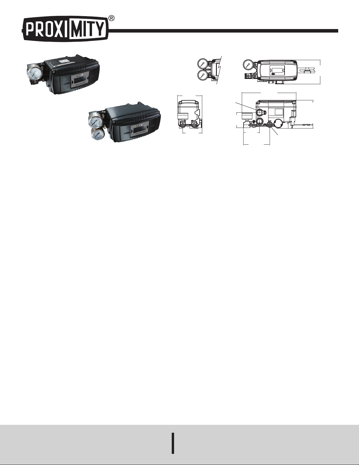
Series 185/285 Smart Positioners
LCD SCREEN
SMART POSITIONER
3
-27/32
[97.50]
3-1/64
[76.50]
4-7/64
[104.20]
SUPPLY
1
/4 NPT
2
-33/64
[64.00]
2-11/32
[
59.60]
4-13/32
[
111.90]
STAINLESS STEEL
4
-31/64
[113.8]
STANDARD
CONDUIT ENTRY
1
/2 NPT
8
-31/64
[215.70]
DOUBLE
A
CTION
S
INGLE
A
CTION
3
-47/64
[95.00]
Specifications - Installation and Operating Instructions
eries 185
S
eries 285
S
he Series 185 and 285 Smart Positioners control valve movements accurately
T
using an input signal of 4 to 20 mA from the controller. In addition, a highly efficient
microprocessing operator built into the product performs various functions such as
auto calibration, PID control, alarm and Hart
eatures
F
LCD allows the user to directly check the positioner condition in the field.
•
Endures severe vibration.
•
• Operates normally regardless of changes in supply pressure during operation.
• Simple to use auto calibration.
• Easily equipped on small actuators because of its small size.
• Low air consumption reduces operating cost.
• Can be used in low voltage (8.5 V), leaving no limitation in controller.
®
• HART
communication available for configurating parameters or monitoring the
valve position.
• Analog feedback signal (4 to 20 mA).
• The adjustment of valve characteristics (linear, quick open, equal percentage)
available.
• Tight shut-close and shut-open can be set in the programming menu.
• PID parameters can easily be adjusted in the field without additional
communicator.
• Split ranges such as 4 to 12 mA, with 12 to 20 mA available.
• The positioner can manually actuate the valve or damper.
• An air filter regulator can be mounted directly to the positioner.
®
protocol.
Bulletin V-185/285
SPECIFICATIONS
Input Signal: 4 to 20 mA DC.
Input Impedance: 460 Ω max @ 20 mA DC.
Enclosure: Aluminum, SS.
Air Supply: 35 to 116 psi (2.4 to 9 bar).
Air Connection: 1/4˝ NPT.
age Connection: 1/8˝ NPT.
G
onduit Connection: 1/2˝ NPT.
C
inearity: ±0.5% FS.
L
Hysteresis: ±0.5% FS.
Sensitivity: ±0.2% FS.
Repeatability: ±0.3% FS.
Air Consumption: .0004 scfm (.01 LPM) at 20 psig (1.4 bar) supply.
Flow Capacity: 2.1 scfm (60 LPM) at 20 psig (1.4 bar) supply.
Stroke: 185: 0.5 to 6 in (10 to 150 mm); 285: 0 to 90°.
Enclosure Rating: NEMA 4X (IP66).
Temperature: Operating: -22 to 185°F (-30 to 85°C).
Weight: 185: 3.3 lb (1.5 kg); 285: 6.4lb (2.9 kg).
Lever: 185: .39 to 1.57 in (10 to 40 mm); 285: NAMUR.
DWYER INSTRUMENTS, INC.
P.O. BOX 373 • MICHIGAN CITY, INDIANA 46360, U.S.A. Fax: 219/872-9057 e-mail: info@dwyer-inst.com
®
HART
is a registered trademark of Hart Communication Foundation
Phone: 219/879-8000 www.dwyer-inst.com
Page 2
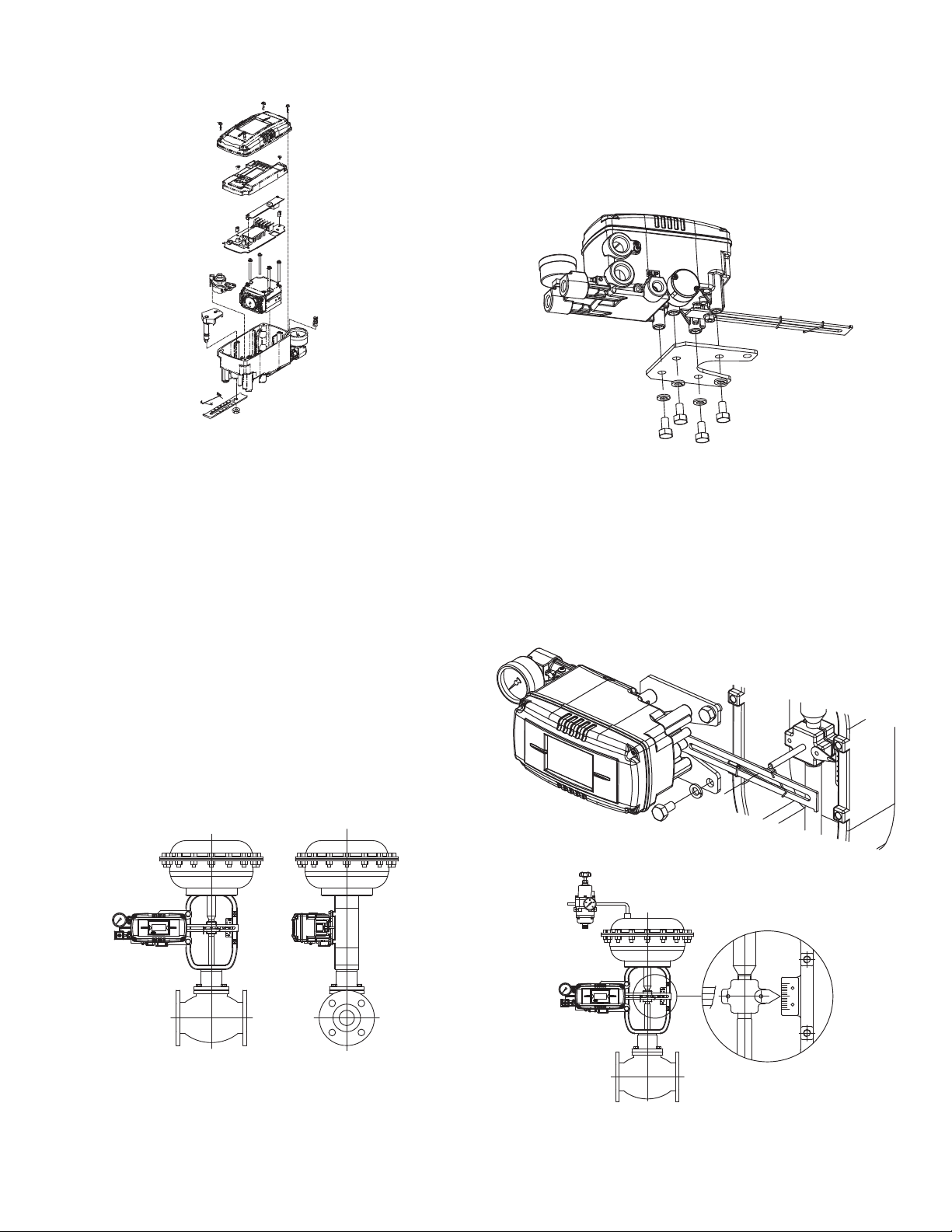
tructure
LCD SCREEN
SMART POSITIONER
0
100
50
L
CD SCREEN
SMART POSITIONER
S
he structure of the 185 is shown below. The Series 285 structure is the same as
T
he linear model without the feedback lever.
t
nstallation
I
ote: When the positioner is replaced or installed with the actuator, make sure of
N
the following:
-All inputs and supply pressure to the valve, actuator and other instruments must
be shut down.
-The control valve must be separated from the system with a bypass valve or other
equipment so that the entire system does not shut down.
-No pressure remains in the actuator.
nstalling Series 185 with Bracket
I
t is necessary to make a proper bracket to attach on the actuator yoke.
I
he most important considerations in the design of the bracket are as follows:
T
Series 185 feedback lever should be at 50% of valve stroke.
-
- Feedback level connection bar of actuator clamp should be connected in the
position so that the valve stroke and the numbers carved on feedback lever are
fitted. If the bracket meets the above conditions, Series 185 can be installed very
asily.
e
. Assemble Series 185 and bracket with bolts. Use standard bolts in bolt holes on
2
he backside of the unit.
t
nstalling Series 185 with Bracket
I
3. After assembling Series 185 and bracket with bolts, attach it using bolt holes of
actuator yoke. Do not tighten completely, there must be some space.
4. Install bar connected with Series 185’s feedback lever on the actuator clamp.
The slot length between Series 185’s feedback lever is .26˝ (6.5 mm), so the
diameter of the connection bar should be less than .25˝ (6.3 mm).
Tools For Installation
• Hexagonal wrenches
• (+) Screw driver
• (-) Screw driver
• Spanners for hexagon head bolts
Series 185 Installation
Series 185 is used for linear motion valves such as Dwyer Instruments’ globe
valves using a spring return type diaphragm actuator or piston actuator. The Series
185 consists of the following components. Be sure that all the components are
included.
1. Series 185 main body
2. Feedback lever and lever spring
3. Flange nut (attached on the bottom of main shaft of Series 185 body)
4. Four hexagon head bolts M8x1.25P
5. Four M8 plate washers
5. Connect the air filter regulator with the actuator temporarily. Set supply pressure
of air filter so that the actuator clamp is positioned at 50% of valve stroke.
Page 3
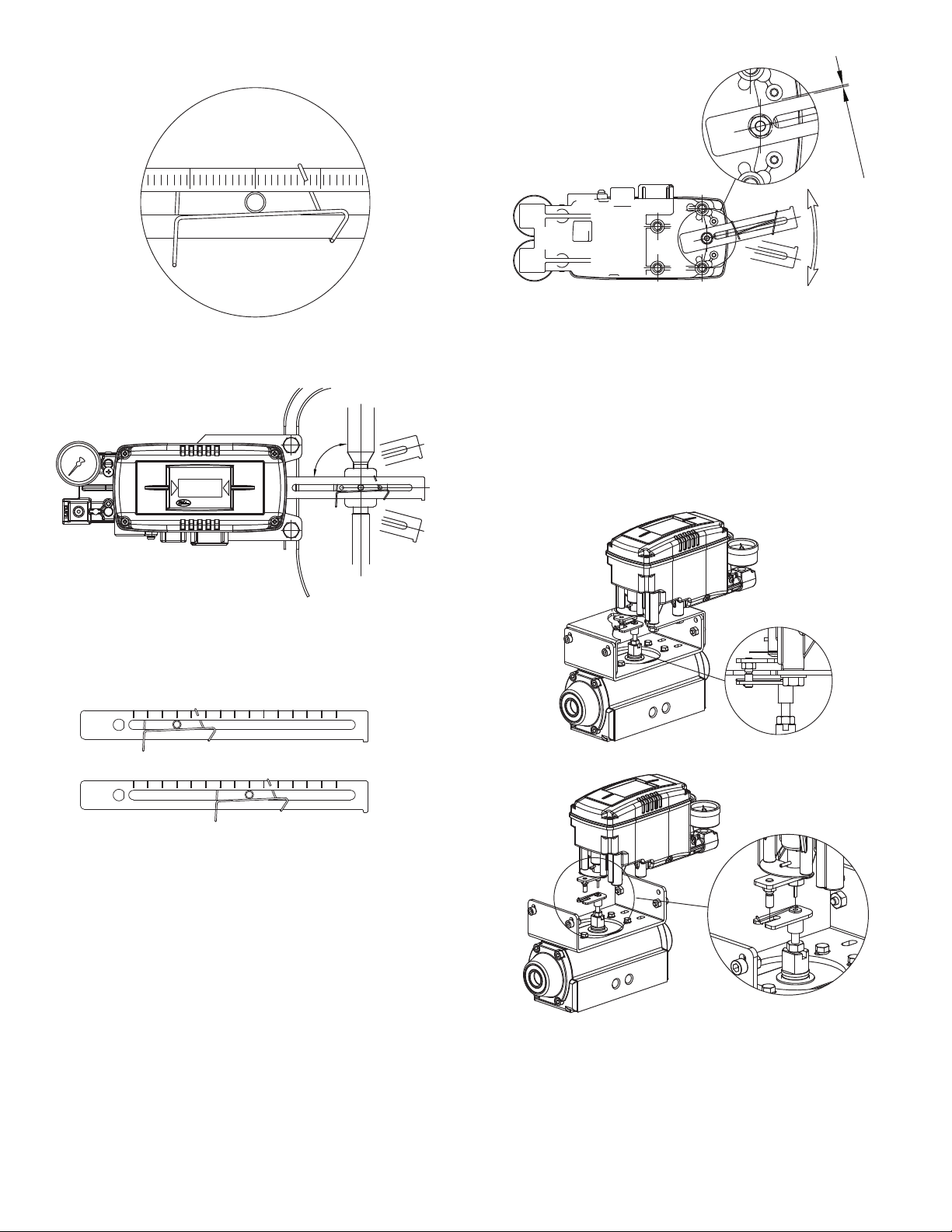
. Insert the connection bar attached on the actuator clamp into the slot of Series
605040
9
0
°
50%
L
CD SCREEN
S
MART POSITIONER
3010 20 40 50 60 70 1501401301201101009080
402010 30 80 90 100 110 120 130 140 150706050
N
o
T
o
u
c
h
!
6
85’s feedback lever. In order to reduce hysteresis, it should appear as shown:
1
7. Check that the Series 185’s feedback lever is level at 50% of valve stroke. If not,
ove bracket or feedback link until it is level. Product linearity becomes work if
m
eries 185 is installed without being level at 50% of valve stroke.
S
9. Once the Series 185 is installed according to the above procedures, tighten the
bolts and nuts of the bracket and feedback lever connection bar completely.
eries 285 Installation
S
eries 285 is designed for rotary motion valves such as Dwyer Instruments’ ball
S
nd butterfly valves using rack and pinion, scotch yoke or complex type actuators
a
whose stem is rotated 90°. Series 285 positioners consist of the following
components:
Series 285 main body
Fork lever and lever spring to attach on actuator
bracket
1
our hex bolts M8x1.25P
F
our M8 plate washers
F
Series 285 Installation Example of Fork Lever
8. Check valve stroke. The numbers indicating stroke are carved in the Series 185’s
feedback lever. Set the connection bar attached on the actuator clamp to the
number on the feedback lever applicable to valve stroke as shown in the following
picture. To set the connection bar and the number, move the bracket attached on
Series 185 or connection bar from side to side.
Stroke 40 mm
Stroke 90 mm
NOTE: After installation, operate the valve from 0 to 100% stroke using an air filter
regulator on the actuator. When the stroke is both 0 and 100%, the feedback lever
should not reach to the lever stopper on the backside of the Series 185 unit. If the
feedback lever reaches the lever stopper, move attachment of Series 185 away
from the yoke center.
Page 4

nstalling Series 285 with Bracket
20
450
6
~11mm
450
I
eries 285 is supplied with a standard bracket. The bracket consists of two parts
S
nd is used with a NAMUR shaft. The bracket is assembled in the factory based on
a
79˝ (20 mm) of actuator stem height. If the actuator stem height is higher, such as
.
1.18˝ (30 mm), or 1.97˝ (50 mm), reassemble the bracket adjusting to the actuator
stem height. Refer to the table below to check hole positions.
ctuator Stem
A
Height (H)
0 mm
2
0 mm
3
0 mm
5
Ex) If H is 30 mm, A-L should be locked in H:30 hole, B-L in H:20, 30, A-R in H:30,
nd H:20, 30 with bolts.
a
1. Typically, actuator stem heights (H) are .79˝, 1.18˝, and 1.97˝ (20, 30, and 50
mm). After checking H, assemble brackets following previous guidelines. The
bracket is set at .79˝ (20 mm) in the factory.
. Attach bracket to the actuator using hex bolts. The diameter of the bracket bolt
2
oles are .24˝ (6 mm). Use spring washers or thread lock compound so the bolts
h
will not be loosened by vibration or impact. The direction of the bracket varies by
operating conditions, but normal direction is depicted in the following picture. That
is, when the piping of actuator and Series 285 is as shown in direction A, the
bracket hole and indicator attached on the bottom of the Series 285 main shaft
should be mounted in the same direction.
Markings of Bolt Holes
A-L
H: 20
H: 30
: 50
H
B-L
H
H
H
: 20, 30
: 20, 30
: 50
A-R
H
H
H
Actuator Stem (H)
Actuator
: 20
: 30
: 50
B-R
: 20, 30
H
: 20, 30
H
: 50
H
.Once the fork lever position is set, lock the check nuts on the bottom of the fork
5
ever by turning clockwise. Set the upper height of the fork lever to .24˝ to .43˝ (6
l
o 11 mm) lower than the upper height of the bracket.
t
racket
B
Fork Lever
Actuator
6. Attach Series 285 unit to the bracket. Fix the clamping pin on the main shaft
center of the Series 285 into the hole of the fork lever. Insert the connection bar
attached on the main shaft lever into the fork lever slot to be locked by the fork lever
pring. This is to fit the main shaft of the Series 285 to the center of the actuator
s
tem. If they are not fitted correctly, too much force on the main shaft will greatly
s
educe product durability.
r
7. Attach Series 285 base and the bracket with hex bolts and plate washers. It is
best to lock the bracket and Series 285 together by inserting four bolts after
checking the position.
Fitting the Pin on the Series 285 Main Shaft Into Fork Lever Hole
Direction A
Attachment Direction of Bracket and Actuator
3. Set the rotation position of the actuator stem as the initial zero point, which is 0%
stroke. For a spring return type actuator, the actuator stem is always rotated to the
zero point without supply pressure, making it easy to check the zero point. If the
actuator is double-acting, check whether the rotation direction of the actuator is
clockwise or counter-clockwise, or the rotation direction of the actuator is using
supply pressure.
4. Set the actuator stem as the initial zero point and install a fork lever as showing
in the following picture. Confirm the position of initial zero point when actuator stem
is turned clockwise and counter-clockwise. Installation angle of fork lever should be
about 45 degrees based on the linear shaft. But the angle is not related to NAMUR
shaft.
PIPING CONNECTION
NOTICE
and piping.
2. It is recommended to attach filter or air filter regulator in front of the supply port
of the Series 285 unit.
Conditions of Supply Pressure
1. Dry air with a dew point that is at least 50°F (10°C) lower than that of the ambient
temperature.
2. Free from solid particles. Result of being passed through 5 micron or finer filter.
3. Does not contain oil or lubricating oil.
4. Comply with ANSI/ISA-57.3 1975(R1982) or ISA S7.3-1975(R1981).
5. Not used beyond the range of 20 to 100 psi (140 to 700 kPa).
6. Set supply pressure of air filter regulator to 10% higher than operating pressure
of actuator.
Conditions of Pipe
Remove foreign objects from inside of pipe.
Do not use squeezed or broken pipe.
To maintain flow rate of Series 285, use a pipe with inner diameter of greater than
.24˝ (6mm) (outer diameter .39˝ (10 mm)).
1. To prevent ingress of moisture, oil and dust, give careful
consideration to the choice of supply pressure compressor
Counter-Clockwise
Clockwise
Page 5

Piping Connection With Actuator
LCD SCREEN
SMART POSITIONER
L
CD SCREEN
SMART POSITIONER
Series 185 and Series 285 can operate either single or double acting actuators.
ingle Acting Actuator
S
o operate a single acting actuator, connect OUT1 port to actuator supply pressure
T
ort. Close off the OUT2 port with the supplied 1/4˝ NPT plug.
p
ouble Acting Actuator
D
or the Series 185 and 285 double acting types, OUT1 and OUT2 ports are used.
F
erminal Plate of Series 185 and 285
T
erminal Connection of Current Input Signal
T
1. Open cover by loosening the four M4 bolts on positioner cover.
2. Loosen locking bolts of terminal plate.
3. Insert a cable through the cable connector in the positioner.
. Use a ring type cable terminal so that it does not come out.
4
. Insert terminal bolts in terminal holes of cable and lock them with (+) terminal and
5
-) terminals on the terminal plate. Tighten terminal bolts with 1.1 lb-ft (15 kfgcm) of
(
torque.
6. Be sure not to change the polarity of the terminals.
Terminal Connection of Feedback Signal
. Open cover by loosening the four screws on positioner cover.
1
2. Loosen locking bolts of terminal plate.
3. Insert a cable through the cable connector in the positioner.
. Use a ring type cable terminal so that it does not come out.
4
. Insert terminal bolts in terminal holes of cable and lock them with (+) terminal and
5
-) terminals on the terminal plate. Tighten terminal bolts with 1.1 lb-ft (15 kfgcm) of
(
torque.
6. Be sure not to change the polarity of the terminals.
Piping Connection Example of Series 185 with Double Acting Actuator
Piping Connection Example of Series 285 with Double Acting Actuator
Power Connection
CAUTION
1. Before connecting terminal, power must be shut off.
2. Use ring type terminal against oscillation, impact, etc.
3. Series 185 and 285 positioners use 4 to 20 mA DC for power. Minimum supply
current is 3.8 mA for all models. Maximum supply current must not exceed 24 mA.
4. In order to protect the Smart Positioner, the ground terminals should be
grounded.
5. Use twisted cable with conductor sectional area at least 0.0019 in
2
(1.25 mm2),
and suitable for 600 V as on conductor table of NEC Article 310. Outer diameter
of cable should be .25˝ to .39˝ (6.35 to 10 mm). Use shielded wire against
electromagnetic waves and noise.
6. Do not install the cable near equipment such as a high-capacity transformer or
motor.
Inner Terminal Connection to Ground
1. The ground is necessary for the safety of the positioner and system.
2. The ground terminals are inside the terminal in the center of the terminal plate and
outside terminal beside outer cable entry. Use any ground terminal that is available.
Resistance must be less than 100 Ω.
Ground Terminal Connection
3. For use with inside ground, open cover by loosening the four screws of positioner
cover.
4. In order to maintain the ground connection, use a ring type ground cable terminal
to prevent it from coming out.
Variable Orifice
Hunting can occur if the actuator volume is too small. In this case, adjust the variable
orifice using a (-) flathead screwdriver. Hunting is prevented by reducing the flow rate
of supply pressure transmitted to the actuator.
Maximum Open
Minimum Open
Page 6

uto Calibration and Basic Operations
A
ystem.
s
CAUTION
Since this makes the valve or actuator move, before auto
alibration, the valve must be separated from the entire
c
Buttons Operations
eries 185 and 285 positioners perform various functions using four buttons. The
S
osition of the buttons is shown below:
p
unctions
utton
B
ENTER>
<
F
Enter to Main Menu and Sub-Menus, Save Adjusted
Parameter Values, etc.
<ESC>
<UP> & <DOWN>
UN mode
R
Return to Previous Menu
ove to Next Menu, Change Parameter Values, etc.
M
After connecting the power to the positioner, the following is displayed on the LCD
in 6 seconds.
RUN on the bottom line means that the Smart Positioner adjusts valve stroke based
on an outside signal (4 to 20 mA) and PV refers to the number on the LCD. In RUN
ode, valve stroke is changed according to input signal.
m
Run PV
1
Run SV %
2
Run SV mA
3
un MV
R
4
Run Vel
5
Run Err
6
Process Value
Set Value
Set Value
anipulate Value
M
Velocity
Error
alve Stroke (%)
V
Input Signal (0 - 100%)
Input Signal (4 - 20 mA)
Motor/Piezo Valve Manipulate Valve (Digit)
Current Valve Stem’s Velocity (Digit)
Difference between SV and PV (%)
uto Calibration Types
A
uto 1 Calibration (AUTO1)
A
n this mode, all parameters necessary for valve operation are set except KP, KI,
I
D and RA/DA. It is used to re-execute calibration by users in the field after being
K
supplied the positioner unit, whose parameters were set by the valve company.
1. Press and hold <ENTER> for 6 seconds in RUN mode and AUTO CAL
message should appear.
. Push <ENTER> and AUTO CAL menu is displayed.
2
. Push <ENTER> at AUTO1 mode and Auto 1 calibration is started.
3
. When Auto 1 calibration is done, ‘COMPLETE’ message will appear on the
4
CD. After 4 seconds the procedure returns to RUN mode.
L
ENTER>
<
seconds
6
COMPLETED
ENTER> <ENTER>
<
Auto 2 Calibration (AUTO2)
ll parameters necessary to operate valve are set. This calibration is used when
A
he positioner is first installed with valve. Refer back to First Auto Calibration.
t
. Press and hold <ENTER> for 6 seconds in RUN mode and AUTO CAL
1
message should appear.
2. Push <ENTER> and AUTO CAL menu is displayed.
3. Push <DOWN> at AUTO CAL and select AUTO 2.
4. Push <ENTER> at AUTO2 mode. Auto 2 calibration is started and the next
odes are displayed in order on the LCD. Normally it will take 3 to 5 minutes
m
or auto calibration in AUTO2 mode. Duration may vary based on actuators
f
olume.
v
5. When Auto calibration is done, ‘COMPLETE’ message appears on the LCD.
After 4 seconds the procedure is returned to RUN mode. Zero, Span, PID
parameters and RA/DA are automatically set when Auto 2 calibration is
completed. Below: Entire Modes and Functions
First Auto Calibration
First auto calibration is usually used when the positioner has not been set, such as
the initial setting with valve at the valve company, or replacement with other product
in the field. In this case, all parameters are set by using AUTO2 calibration.
Notice: When the positioner is installed on the valve in the field after setting, we
recommend using AUTO1 calibration rather than AUTO2 calibration. This is
because the AUTO 2 calibration parameters have been factory set to the optimum
settings.
AUTO1
AUTO2
AUTO3
Zero Point
°
°
x
End Point
°
°
x
KP, KI, KD
x
°
°
RA/DA
x
°
°
KP
This is a proportion constant value that is correction by error %. If this value is too
big, there can be hunting, even though it finds position by the input signal. If the
value is too small, accuracy gets worse.
KI
This is an integral constant value adding or subtracting the correction that is
corrected error % on the previous correction signal. If this value is too big, there
can be oscillation. If it is too small, the time to find the exact position increases.
KD
This is a differential constant value adding the previous correction signal with the
changing correction signal by the error % change rate.
RA/DA
Direct acting (DA) or Reverse acting (RA).
ENTER>
<
seconds
6
<ENTER>
ENTER> <DOWN>
<
COMPLETED
Auto 3 Calibration (AUTO3)
All parameters necessary to operate valve are set except zero and end point. This
function is used to re-execute auto calibration without changing the zero and end
point after adjusting them manually.
1. Press and hold <ENTER> for 6 seconds in RUN mode and AUTO CAL
message should appear.
2. Push <ENTER> and AUTO CAL menu is displayed.
3. Push <DOWN> at AUTO CAL and select AUTO 3.
4. Push <ENTER> and AUTO3 calibration is started.
5. When Auto calibration is done, ‘COMPLETE’ message appears on the LCD.
After 4 seconds the procedure is returned to RUN mode.
Manual Mode
Manual mode is used to raise or lower the valve stem manually. In this mode, valve
stroke is adjusted only by operating buttons, not by the current input signal. This
mode does not affect controlling data registered in the positioner. It only is used to
move the valve stem up and down.
1. Press and hold <ENTER> for 6 seconds in RUN mode until AUTO CAL
message is displayed.
2. Scroll with <DOWN> button until MANUAL mode is displayed.
3. Push <ENTER> to enter MANUAL mode. Two lines appear on the LCD. The
upper line indicates valve stroke by percentage and the lower line indicates
absolute value of inner resistance of the positioner. “MA” means that Manual
mode is in operation.
4. Push <UP> or <DOWN> and valve stem moves up or down. Regardless of
RA/DA, if <UP> is pushed, valve stem moves up (in case of linear valve). If
<DOWN> is pushed, valve stem moves down. To make the valve stem move
fast, push <ENTER> with <UP>, or <DOWN>.
<UP> only
<UP> + <ENTER>
<DOWN> only
<DOWN> + <ENTER>
Increase stem value slowly
Increase stem value quickly
Decrease stem value slowly
Decrease stem value quickly
5. Push <ESC> to exit MANUAL mode.
Page 7

arameter Mode (PARAM)
P
arameter Types
P
here are four parameter modes: Dead Zone, KP, KI, and KD.
T
hese values are reflected as soon as they are changed, therefore the appropriate
T
values are found by checking the valve’s motion in real time.
Adjustment of Dead Zone (dEAdZONE)
his is the range of error % that the positioner is not adjusted. Hunting or oscillation
T
ue to friction between the stem and packing is prevented by this parameter.
d
. Press and hold <ENTER> at RUN mode for 6 seconds and AUTO CAL
1
essage appears.
m
2. Scroll with <DOWN> until PARAM mode is displayed.
3. Push <ENTER> and dEAdZONE mode is displayed.
4. Push <ENTER> again and *EAdZONE message appears.
. Adjust dEAdZONE value by pushing <UP> or <DOWN>. Adjusted valued is
5
pplied immediately without additional operation. Users can easily check its
a
djustment by changing the current input signal to the positioner. Optimum
a
control value is found by adjusting values during the valve operation.
6. Push <ENTER> to save the value. +EAdZONE message appears on LCD.
7. Push <ESC> to exit dEAdZONE mode.
<ENTER>
6 seconds
<ENTER> <UP>/<DOWN>
COMPLETED
<ENTER>
6 seconds
then <ENTER>
<ENTER>
<ESC>
3 times
KP
1. Press and hold <ENTER> at RUN mode for 6 seconds and AUTO CAL
message appears.
2. Scroll with <DOWN> until PARAM mode is displayed.
3. Push <ENTER> and dEAdZONE mode is displayed.
4. Scroll with <DOWN> until KP mode is displayed.
5. Push <ENTER> at KP mode and *KP message appears on LCD.
6. Adjust KP value with <UP> or <DOWN>. Adjusted value is applied immediately
without additional operation. Users can easily check its adjustment by changing
the current input signal to the positioner. Optimum control value is found by
adjusting the values during valve operation.
7. Push <ENTER> to save the value and +KP message appears on LCD.
8. Push <ESC> to exit KP mode.
AND CAL
H
hen auto calibration is started, Series 185 and 285 positioners set zero points
W
nd end points based on full stroke. HAND CAL allows for user defined zero and
a
nd points.
e
Hand Calibration Types
PV_ZERO: Edit mode to change the zero point of valve.
V_END: Edit mode to change the end point of a valve.
P
R_ZERO: Edit mode to change the zero point of transmitter.
T
R_END: Edit mode to change the end point of transmitter.
T
Adjustment of valve zero point (1 to 5) and end point (6 to 10).
PV_ZERO
. Press and hold <ENTER> at RUN mode for 6 seconds and AUTO CAL
1
essage appears.
m
. Scroll with <DOWN> until HAND CAL mode is displayed.
2
3. Push <ENTER> and PV_ZERO mode is displayed.
4. Push <ENTER> at PV_ZERO mode and *PZ mode is started. The valve stem
will move automatically to the current zero point. On the LCD, the valve stroke
is displayed as 0%. *PZ indicates the zero point is ready to be set.
. Adjust valve stem by pushing <UP> or <DOWN>. When valve stem is at the
5
esired zero point, save it by pushing <ENTER>.
d
. Push <ESC> to exit PV_ZERO mode.
6
PV_END
1. To change valve end point, scroll with <DOWN> at HAND CAL menu and select
PV_END.
. Push <ENTER> at PV_END mode and *PE mode is displayed. The valve stem
2
ill move automatically to the current end point. On the LCD, the valve stroke
w
s displayed as 100%. *PE indicates the end point is ready to be set.
i
3. Adjust valve stem by pushing <UP> or <DOWN>. When the valve stem is at
the desired end point, save it by pushing <ENTER>.
4. Push <ESC> to exit PV_END mode.
ENTER>
<
seconds
6
<ENTER> <UP>/<DOWN>
<DOWN> <ENTER> <UP>/<DOWN>
DOWN>
<
times
3
then <ENTER>
ENTER>
<
<ESC>
then <ENTER>
PT
<ENTER> <DOWN>
<UP>/<DOWN>
then <ENTER>
3 times
<ESC>
3 times
<ENTER>
COMPLETED
1. Press and hold <ENTER> at RUN mode for 6 seconds and AUTO CAL
message appears.
2. Scroll with <DOWN> until PARAM mode is displayed.
3. Push <ENTER> and dEAdZONE mode is displayed.
4. Scroll with <DOWN> until PT mode is displayed.
5. Push <ENTER> at PT mode and *PT message appears on LCD.
6. Adjust PT value with <UP> or <DOWN>. Adjusted value is applied immediately
without additional operation. Users can easily check its adjustment by changing
the current input signal to the positioner. Optimum control value is found by
adjusting the values during valve operation.
7. Push <ENTER> to save the value and +PT message appears on LCD.
8. Push <ESC> to exit KP mode.
<ENTER> <DOWN>
<UP>/<DOWN>
then <ENTER>
<ESC>
3 times
7 times
<ENTER>
COMPLETED
COMPLETED
<ESC>
Page 8

alve Mode
100%
Strok
0
4
20
mA
Quick Open
Linear
E
Q%
V
his mode adjusts the various characteristics.
T
ction Type (ACT)
A
It can be set to Direct Action (DA) or Reverse Action (RA).
Adjustment of Acting Type (ACT)
. Press and hold <ENTER> at RUN mode for 6 seconds and AUTO CAL
1
essage appears.
m
. Scroll with <DOWN> until VALVE mode is displayed.
2
. Push <ENTER> and ACT RA (in case of Reverse Acting) is displayed.
3
4. Push <ENTER> and *ACT RA is displayed.
5. Adjust to *ACT DA by pushing <UP> or <DOWN> and save it with <ENTER>.
+ACT DA message appears.
. Push <ESC> to exit ACT RA mode.
6
djustment of User Characteristics (USER SET)
A
. Push <ENTER> at VALVE mode and scroll with <DOWN> to select USER SET.
1
. Push <ENTER>. *PO SET mode is displayed. In this mode, users can adjust the
2
irst point of characteristic in 16 points. the number on the LCD is the valve stroke
f
percentage set to P0.
3. Adjust the valve stroke percentage using <UP> or <DOWN>.
4. Save with <ENTER>. While P0 value is being saved, *P1 SET mode is
isplayed.
d
. *P1 SET mode is used to adjust the second point characteristic in 16 points.
5
djustment method is the same as P0* SET mode.
A
. Continue steps from P2 to P15.
6
7. After adjusting valve stroke percentage at *P15 SET mode, save with <ENTER>.
8. +SER SET is displayed. All sixteen points of valve stroke percentage are set.
9. Push <ESC> to exit USER SET mode.
haracteristics (CHAR)
C
<ENTER>
6 seconds
<ENTER> <UP>/<DOWN>
COMPLETED
<DOWN>
3 times
then <ENTER>
<ENTER>
<ESC>
3 times
Set Characteristics. There are three types of valve characteristics: Linear (LIN),
EQ% (EQ), and Quick Open (QO). The following is the example of the three
characteristic curves.
<ENTER>
6 seconds
UP>/<DOWN>
<
hen <ENTER>
t
ENTER> <ENTER>
<
<DOWN>
3 times
ENTER> <UP>/<DOWN>
<
seconds
6
<ENTER>
hen <ENTER>
t
Adjustment of Characteristics (CHAR)
1. To change linear characteristics, scroll with <DOWN> at VALVE menu and select
CHAR LIN (in case of linear characteristics).
2. Push <ENTER>. *HAR LIN mode is displayed and charactertistics can be set to
LIN, EQ, QO or USR.
3. Adjust characteristics (ex: EQ) by pushing <UP> or <DOWN> and save it with
<ENTER>. + HAR EQ is displayed.
4. Push <ESC> to exit CHAR LIN mode.
User Characteristics (USER SET)
When a specific characteristic is needed but not included in the above
characteristics, the user can make a specific characteristic curve by choosing 16
points voluntarily.
Page 9

ight Shut Open (TSHUT OP)
T
his allows the user to fully open valve at input values around 20 mA.
T
djustment of Tight Shut Open (TSHUT OP)
A
1. To adjust Tight Shut Open, scroll with <DOWN> at VALVE menu and select
TSHUT OP.
2. Push <ENTER> and *SHUT OP mode is displayed. In this mode users can set
troke at the time of Tight Open. Initial setting is done as 100% which means
s
he TSHUT option is disabled. Adjust the value (ex: 95.0%) by pushing <UP>
t
r <DOWN> and save with <ENTER>. +SHUT OP is displayed.
o
. Push <ESC> to exit TSHUT OP mode.
3
IEW Mode
V
his mode provides users with various information about the Series 185 and 285
T
ositioners. In this mode, users can change the valve stroke types displayed on
p
CD to % or numbers. Refer to the next table for information and description
L
displayed on VIEW mode.
1. Press and hold <ENTER> at RUN mode for 6 seconds and AUTO CAL message
appears.
. Scroll with <DOWN> and select VIEW menu.
2
. Push <ENTER> and check information using <UP> or <DOWN>.
3
. Push <ESC> to exit VIEW mode.
4
<ENTER>
6 seconds
<ENTER>
ight Shut Close (TSHUT CL)
T
his allows the user to completely close valve at input values around 4 mA.
T
6 seconds
<DOWN>
3 times
<DOWN>
3 times
<ENTER>
<ENTER>
Adjustment of Tight Shut Close (TSHUT CL)
1. To adjust Tight Shut Close, scroll with <DOWN> at VALVE menu and select
TSHUT CL.
. Push <ENTER> and *SHUT CL mode is displayed. In this mode users can set
2
troke at the time of Tight Close. Initial setting is done as 0.3%. 0% means
s
he TSHUT option is disabled. Adjust the value (ex: 0.5%) by pushing <UP>
t
or <DOWN> and save with <ENTER>. +SHUT CL is displayed.
3. Push <ESC> to exit TSHUT CL mode.
ENTER>
<
seconds
6
<UP>/<DOWN>
then <ENTER>
DOWN>
<
times
4
<ESC>
3 times
ENTER>
<
<ESC> 3 times
then <ENTER>
Split Range Control (SPLIT)
This allows the user to control entire stroke with input signals of 4 to 20 mA, 4 to
12 mA or 12 to 20 mA.
Adjustment of Split Range (SPLIT)
1. To change Split Range, scroll with <DOWN> at VALVE menu and select
SPLIT.
2. Push <ENTER>. *SPLIT mode is displayed. The numbers on the LCD are the
range of current signal input to the positioner. 4.20 indicates 4-20 mA, 4.12
indicates 4-12 mA, and 12.20 indicates 12-20 mA setting.
3. Select desired Split Range and save with <ENTER>.
4. Push <ESC> to exit SPLIT mode.
<ENTER>
6 seconds
<UP>/<DOWN>
then <ENTER>
<DOWN>
5 times
<ESC>
3 times
<ENTER>
<ESC> 3 times
then <ENTER>
YT-2500L
ERSION
V
ART V
H
OL AddR
P
bIAS VI
Y 0d
0
FULL_OP
FULL_CL
VM NOR
rro
E
ALUE I
V
ABS
ENTER>
<
times
4
<ESC>
escription
D
ositioner model
P
Main software version
HART Protocol version
Channel address that is used in HART Protocol
bIAS value for motor/piezo valve control. Can be adjusted only by
anufacturer.
m
otal used time duration. If a unit was used less than 1 minute, the
T
ime does not accumulate.
t
Time elapsed for valve to fully open.
Time elapsed for valve to fully close.
Display type of valve stroke on LCD (either in percentage or value).
Display error code or warning message <Figure XX>.
urrent I-Value. Can be adjusted only by manufacturer.
C
Display absolute resistance value.
ENTER> <UP>, <DOWN>
<
OMPLETED
C
onfirm the changes,
c
hen <ESC>
t
Information Checked on VIEW Mode
Error and Warning Code
If there are any problems during Series 185 and 285 positioner operation, you can
check the error and warning code at VIEW mode as follows:
Error Code
This code is displayed when the Series 185 and 285 positioner control becomes
impossible. Code C, D applies.
Error Code
MT ERR L
Code Description and Cause
Positioner is improperly installed.
Positioner lever is not parallel to
the ground at 50% point. Lever is
at lower position than actual 50%
Action
Re-install/mount the positioner.
Make sure the feedback lever
does not touch the stopper at both
0 and 100%.
point.
MT ERR H
Positioner is improperly installed.
Positioner lever is not parallel to
the ground at 50% point. Lever is
at lower position than actual 50%
Re-install/mount the positioner.
Make sure the feedback lever
does not touch the stopper at both
0 and 100%.
point.
CHK AIR
Valve does not operate when
positioner receives “Full Open”
Check if supply pressure is stable
and appropriate.
signal during auto calibration.
RNG ERR
Operating angle is too small due
to improper mounting of
Adjust bracket so the positioner
can be mounted closer to actuator.
positioner.
C
Error 10% or above persists more
than 1 minute.
No valve movement.
Friction of valve is too large.
Perform BAS calibration.
Check setting pressure of actuator
and set the pressure as
recommended.
Setting pressure of actuator
changes.
D
I-Value reaches at maximum or
minimum limit point.
Friction of valve changes.
Setting pressure of actuator
Perform AUTO calibration.
Check setting pressure of actuator
and set the pressure as
recommended.
changes.
Page 10

arning Code
Used timeUser Set
ENT
: Enter button
Manual Mode
Auto 2
Auto cal
RUN Mode
E
NT
(5 sec)
E
SC
ESC
Auto 1
E
NT
BIAS
Auto 3
E
SC
ESC
V_O
E
SC
E
SC
Hart ver.CharacterK P
End point
ViewValveHand calParameter
ESCESC ESC ESCESC
ESC
Start point
Dead Zone
ESC ESC
E
NT
E
NT
ESC
Sof ver.
RA / DA
E
NT
E
NT
BIAS
Tight shut onTR end point
K D
Tight shut oTR start point
K I
E
SC
E
SC
E
SC
ESC ESCESC
Polling Add
E
SC
ESC
E
SC
E
SC
E
SC
E
SC
I value
Split control
E
SC
E
SC
: Up button
ESC
: Down button
: Esc button
Error code
Full close time
ESC
Full open time
ESC
ESC
View method
ESC
ESC
ESC
ESC
E
SC
K I_
K P_
ESC
K D_
W
his code is displayed when the positioner control is available but there is a
T
ossibility of malfunction or low accuracy. Code B, F, G, H applies.
p
arning Code
W
B
Code Description and Cause
PV end-PV zero range is below
00. The angle of feedback
5
ever is too small.
l
Action
e-install/mount the positioner.
R
ake sure the feedback lever
M
oes not touch the stopper at
d
oth 0 and 100%.
b
After re-installation, perform
AUTO1 calibration.
F
Time elapsed for either full-open
or full-close is less than 1
econd.
s
he size of the actuator is
T
oo small.
t
v zero is below 100.
G
P
The angle of feedback lever
is too large.
H
Pv end is over 4000.
he angle of feedback lever
T
s too large.
i
Use variable orifice.
eplace actuator with larger
R
apacity.
c
Re-install/mount the positioner.
After re-installation, perform
AUTO1 calibration.
e-install/mount the positioner.
R
fter re-installation, perform
A
UTO1 calibration.
A
irmware MAP
F
AINTENANCE/REPAIR
M
pon final installation of the Series 185/285, no routine maintenance is required.
U
he Series 185/285 is not field serviceable and should be returned if repair is
T
eeded. Field repair should not be attempted and may void warranty.
n
WARRANTY/RETURN
Refer to “Terms and Conditions of Sales” in our catalog and on our website. Contact
ustomer service to receive a Return Goods Authorization number before shipping
c
he product back for repair. Be sure to include a brief description of the problem
t
lus any additional application notes.
p
©Copyright 2013 Dwyer Instruments, Inc. Printed in U.S.A. 6/13 FR# RB-443952-00 Rev. 2
DWYER INSTRUMENTS, INC.
P.O. BOX 373 • MICHIGAN CITY, INDIANA 46360, U.S.A. Fax: 219/872-9057 e-mail: info@dwyer-inst.com
Phone: 219/879-8000 www.dwyer-inst.com
 Loading...