

Page 1
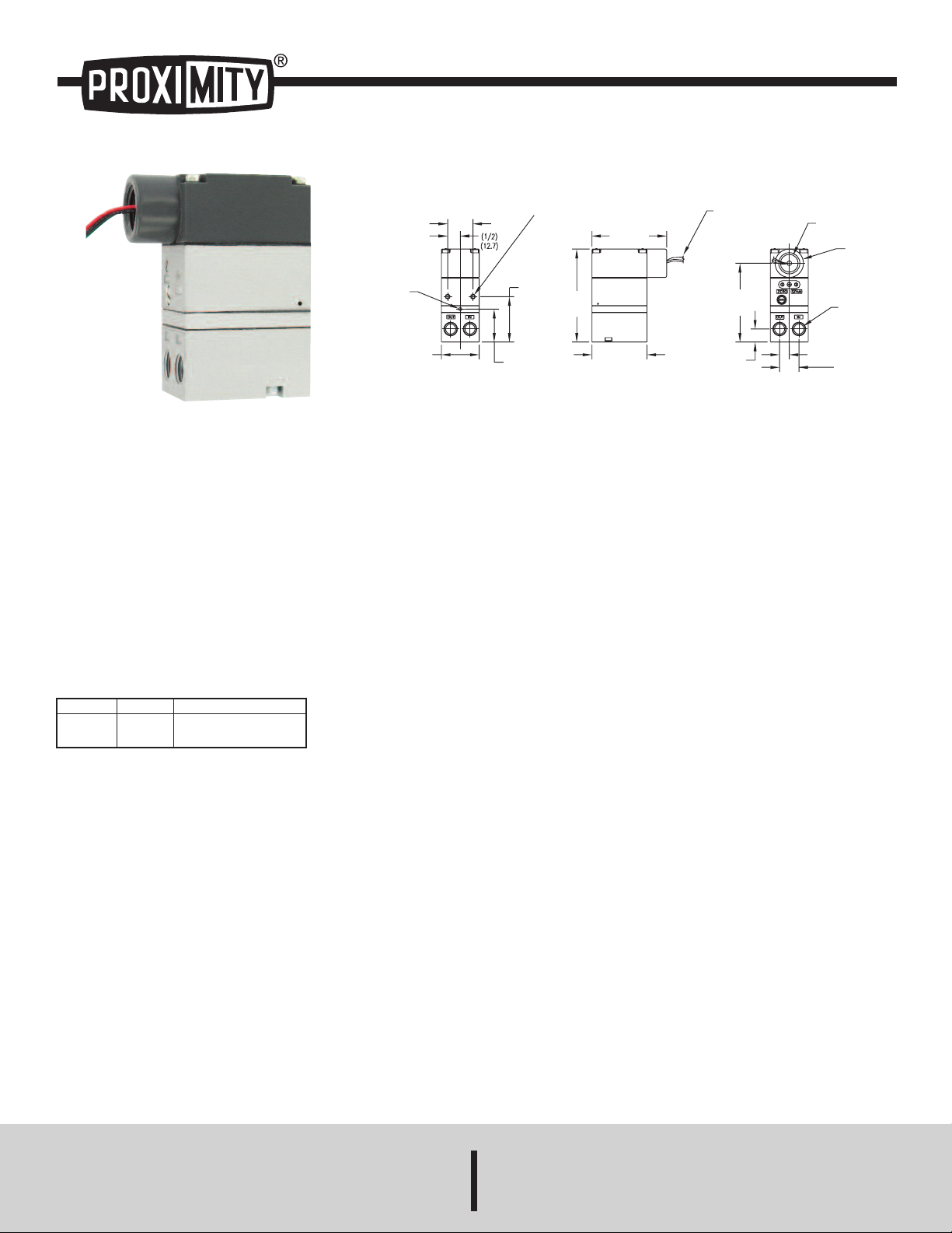
Series 2800 Current to Pressure Transducer
1
[25.4]
Ø1/8
[
Ø3.17]
1-1/2
[38.1]
1-19/64
[33.0]
1-51/64
[45.7]
3-11/16
[
93.7]
MOUNTING HOLES
#10-32 UNF-2B X 3/8 DP
2 PLCS
2-3/16
[
55.4]
2
-15/16
[74.7]
22 GA. WIRE LEADS
APPROX. 18˝ LONG
POS, NEG, GRD
3-1/8
[
79.2]
3
3/64
[13.1]
25/64
[9.72]
4
9/64
[19.4]
1
/2 NPT
Ø1-1/8
[Ø28.7]
IN & OUT PORTS
1/4-18 NPT
4 PLCS
Specifications - Installation and Operating Instructions
Bulletin V-4
The Series 2800 Current to Pressure Transducer converts a current
input to a linearly proportional pneumatic output pressure. This unit
utilizes a closed loop pressure feedback system that closely controls
output and compensates for vibration, mounting angle, temperature, and
supply pressure variations. These characteristics make this unit ideal for
field mounting on a valve. The control mechanism is a piezoceramic
actuator encapsulated in a protective skin, which provides a constant
defense against humidity and contaminants. These features make this
unit ideal for use in demanding applications. The 2800 also comes in a
NEMA 4X enclosure and is field reversible. It is FM and CSA approved
intrinsically safe, as well. For ease of installation, this model has input
and output ports on both the front and back and can be easily panel
mounted.
Model
2813-WP
2816-WP
Input
4-20 mA
4-20 mA
Output
3-15 psig (0.2-1.0 bar)
6-30 psig (0.4-2.1 bar)
SPECIFICATIONS
Service: Oil free, clean dry air filtered to 40 microns.
Input Signal: 4-20 mA.
Air Supply: Minimum: 5 psig (0.3 bar) above maximum output;
Maximum: 100 psig (6.9 bar).
Output: 3 to 15 psig (0.2 to 1.0 bar), 6 to 30 psig (0.4 to 2.1 bar).
Accuracy: ±0.1% of span.
Hysteresis: ±0.1% of span.
Repeatability: ±0.1% of span.
Deadband: 0.02% of span.
Power Requirement: Loop powered.
Temperature Limits: Operating: -40 to 160°F (-40 to 71°C); Storage: -
40 to 200°F (-40 to 93°C).
Pressure Connections: 1/4˝ female NPT.
Electrical Connection: 1/2˝ female NPT.
Air Consumption: 0.025 scfm (0.01 l/s) at midrange typical.
Output Capacity: 4.5 scfm (2.1 l/s) at 25 psig (1.7 bar) supply; 12.0
scfm (5.7 l/s) at 100 psig (6.9 bar) supply.
Enclosure: Chromate-treated aluminum with epoxy paint.
Enclosure Rating: NEMA 4X (IP65) and Intrinsically safe.
Weight: 0.8 lb (0.37 kg).
Agency Approvals: CSA, CE, FM.
PROXIMITY CONTROLS
A DIVISION OF DWYER INSTRUMENTS, INC.
P.O. BOX 373 • MICHIGAN CITY, INDIANA 46360, U.S.A.
Phone: 219/879-8000 www.dwyer-inst.com
Fax: 219/872-9057 e-mail: info@dwyer-inst.com
Page 2
INSTALLATION
GREEN LEAD (GND)
RED LEAD (+)
BLACK LEAD (-)
ZERO
ADJUSTMENT
SPAN
ADJUSTMENT
The Series 2800 transducer is a force balance device in which the piezo
actuator is positioned in relation to a nozzle as the input signal is varied.
The application of an electrical signal causes axial movement of the
actuator. The actuator moves toward the nozzle and creates back
pressure which acts as a pilot pressure to an integral booster relay.
Mounting
Each Series 2800 comes with a mounting kit which enables, panel or
wall mounting of the unit. Optional mounting kits are available for DINrail, pipe, or valve mounting. The 2800 may be mounted at any angle.
Panel: With access to rear of panel, attach transducer to panel using two
10-32 screws and the two threaded mounting holes on the back of the
unit. With no access to the rear of a panel, attach bracket to transducer
using two 10-32 holes on the back of the unit and mount bracket to panel
using four 10-32 screws.
Inline: The Series 2800 has been designed to mount inline to a standard
valve yoke with the A-180 valve mounting kit.
The A-182 pipe mounting kit includes the bracket, U-bolt, and nuts
needed to mount the transducer to a 1-1/2˝ pipe. Just attach the bracket
to the transducer using the two 10-32 holes on the back of the unit. Then,
place the U-bolt around the pipe and through the bracket. Finally, place
the nuts on the U-bolt and tighten.
Pneumatic Connections
Clean all pipe lines to remove dirt and scale before installation. Supply
air must be filtered to 40 microns and free of moisture and lubricants.
Two 1/4˝ NPT ports are provided for supply air connections. Either port
may be used. The unused port must be plugged with the pipe plug
included with the unit.
Two 1/4˝ NPT ports are provided for pneumatic output connections.
Either port may be used and one may be used for the mounting of an
output gage. If no gage is installed, the unused port must be plugged
with the pipe plug included with the unit. Avoid getting pipe sealant inside
the piping or transducer.
Equipment Ratings:
Intrinsically safe for Class I, II, and III, Division 1, Groups C, D, E, F, and
G hazardous (classified) locations and intrinsically safe for Class I, Zone
0, Group IIB hazardous (classified) locations and suitable for Class I, II,
and III, Division 2, Groups A, B, C, D, F, and G.
CSA Intrinsically Safe Ratings:
Class I, Division 2, Groups A, B, C and D; Class II, Division 2, Groups F,
and G; Class III. Rated 7 to 30 VDC, 4 to 20 mA; Temperature Code T4;
Maximum Ambient 70°C.
Ex ia IIB (Class I, Zone 0, Group IIB); Temperature Code T4; Intrinsically
safe with the following entity Parameters when installed as per drawing
531-990-044; Ui = 30 V, li = 125 mA, Pi = 0.70 W, Ci = 0 µF, Li = 0 mH.
OPERATION
Calibration
All units are shipped from the factory calibrated, direct acting. If the user
requires a different mode of operation (i.e. reverse acting, split range) it
is necessary to reposition internal electrical switches as indicated in the
following sections. Though the units are factory calibrated for direct
acting it is suggested that the user check the calibration. It is not
necessary to remove the cover of the unit for calibration if the direct
acting mode is desired.
Direct Acting Calibration
In direct acting operation the unit is calibrated so that minimum input
signal corresponds to minimum output pressure and increasing input
signal results in increasing output pressure. Apply the minimum input
signal of the range being used (e.g. 4mA) (see figure 2). Observe the
output pressure. If necessary, adjust the zero screw until reaching
minimum output pressure setting. Turn zero screw clockwise to
decrease and counter-clockwise to increase.
Apply the maximum input signal of the range being used (e.g. 20 mA).
Observe the output pressure. If necessary, adjust the span screw until
reaching maximum output pressure setting. Turn span screw clockwise
to decrease and counter-clockwise to increase. After setting the span it
will be necessary to recheck the zero. Repeat steps 1-4 until both end
points are at required values.
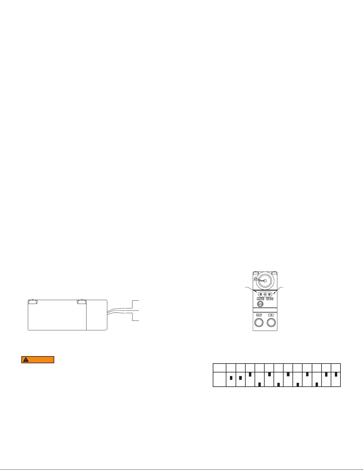
Electrical Connections
Electrical connections are made to the red (+) and black (-) leads. The
green lead is furnished for case ground (see figure 1).
Figure 1
I/P Conduit Connection
WARNING
friction and must be taken into account during installation.
The I/P transducer enclosure contains aluminum and is
considered to constitute a potential risk of ignition by impact or
Factory Mutual Research Corporation (FM) Intrinsically Safe
Ratings: IS / I, II, III / 1 / CDEFG / T4 Ta = 70°C - 431-990-023; Entity;
Type 4X NI/1/2/ABCD; S/II, III/2/FG/T4 Ta = 70°C; Type 4X. Entity
Parameters: Ui (Vmax)=30V, Li (lmax) = 125 mA, Pi = 0.70 W, Ci = 0
µF, Li= 0 mH
Zero Adjustment and Span Adjustment
Signal
4-20 mA
Direct Acting - Position of switches for forward acting operation. Standard
Switch 1 2 3 4 5 6 7 8 9 10 11 12
ON
OFF
setting as supplied by factory.
Figure 2
Figure 3
Page 3

Reverse Acting Calibration
When calibrated to operate in the reverse acting mode the minimum
input signal produces the maximum output pressure and increasing the
input signal results in decreasing the output pressure. Setting the unit to
operate in the reverse acting mode is accomplished by positioning
internal electrical switches.
Disconnect input signal and supply pressure. Take off the top cover by
removing the four screws.
CAUTION
o not reverse the input leads. Avoid touching circuit board.
D
horting possible.
S
Position switches as illustrated in figure 4. Replace cover. Set the input
signal to the minimum value being used. Turn the zero screw to set the
maximum output pressure. Set the span by applying the maximum input
signal. Turn the span screw to set the minimum output pressure. It may
be necessary to repeat steps above until both end points are at desired
values.
Switch 3 4 5 6 7 10
ON
FF
O
Position of Switches for Reverse Acting Operation
Note: Switches not shown match Direct Acting Setting
Figure 4
(see Figure 3)
Split Range
When calibrated to operate in the split range mode, a full input signal (i.e.
4-20 mA) will operate the unit at one half the normal output span (i.e. 39 psig, 9-15 psig). Setting the unit to operate in the split range mode is
accomplished by positioning internal electrical switches. Disconnect
input signal and supply pressure. Take off the top cover of the unit by
removing the four screws.
MAINTENANCE
OTICE
N
nder normal circumstances, no maintenance should be
U
equired.
r
Cleaning
If clean, dry air is not used the orifice can become blocked. To clean, first
turn off supply air, then remove the screw located under the zero
adjustment. Unplug the orifice by using a wire that has a smaller
diameter than 0.012˝ (0.30mm). Use compressed air to blow out any
loose particles inside the orifice screw assembly.
Precautions
The bonnet should be removed only if a different operation mode is
desired which requires a change in circuit board switch settings. In this
case, precautions are necessary.
Never handle circuit board unless properly grounded to prevent ESD
(Electro-static Discharge).
If ESD grounding equipment is not available, hold the 2800 by its
castings and adjust switches using a non-conductive device such as a
pencil or a small rubber handled screwdriver.
Never remove circuit board for any reason. This will shift other
components and possibly damage the pressure sensor, both cases
resulting in malfunction.
Use caution when replacing bonnet. If any resistance is felt, remove
bonnet and determine the interference. Typically it will be the strain relief
grommet on the wires. The grommet should be oriented so it sits beside
the switches.
Clean and dry air should be used with the 2800. Foreign matter in the
supply line can clog the orifice openings. (.013˝ for a 3-15 psig unit,
smaller for higher range unit.) Foreign matter can also collect on the
actuator causing erratic operation. Moisture in the supply line can
damage circuit board components.
CAUTION
Avoid touching circuit board. Shorting possible.
Position switches as illustrated in figure 5. Replace cover. After setting
switches, refer to the appropriate calibration procedure (Direct Acting or
Reverse Acting) to get to desired output range (i.e. 3-9 psig, 9-15 psig).
Switch 1 2
Signal
4-20 mA
Position of Switches for Split Range Operation
Note: Switches not shown match Direct Acting Settings
ON
OFF
Figure 5
(see Figure 3)
The electrical specifications as outlined in these instructions must be
complied to. If more than one 2800 unit is driven by the same PLC, there
must be a minimum of 9.5 VDC available to each unit.
If difficulty is experienced during calibration or if turning the zero or span
screw has no effect on the unit, a resetting technique can be taken. Turn
both the zero and span screw a minimum of 30 revolutions in one
direction. Then turn both screws exactly 15 revolutions in the opposite
direction. This procedure will put the potentiometers at their midpoint of
effective adjustability. Next, calibrate to desired settings starting with the
zero screw.
Reverse Acting Mode: For reverse acting units, the zero adjustment
refers to the minimum electrical signal and maximum output pressure.
The span refers to the maximum signal and the minimum output
pressure. For calibration in reverse mode the resetting technique can be
taken if necessary and calibration should always begin with the zero
screw.
Page 4

TROUBLESHOOTING
Problem
Sluggish performance
or reduced range
Leakage
Low or improper span
Erratic Operation
Check
Blocked orifice
Supply pressure
Connections
Supply pressure connections
Moisture in air supply
Loose wires or connections
NOTICE
ARNING
W
effect of pressure present at the supply port. If devices connected to the output port
have a pressure rating less than the pressure present at the supply port, then
ressure relieving or pressure limiting devices must be employed to protect the
p
evices from over pressurization, possibly causing physical damage, personal
d
njury and/or property damage.
i
The Series 2800 Current to Pressure Transducers are not field repairable and
should be returned if repair is needed (field repair should not be attempted and may
void warranty). Be sure to include a brief description of the problem plus any
elevant application notes. Contact customer service to receive a return goods
r
uthorization number before shipping.
a
f problems are not solved by troubleshooting procedures,
I
contact an applications engineer for further assistance.
ailure Modes: This device must not be used for protecting
F
final control elements connected to the output port from the
©Copyright 2013 Dwyer Instruments, Inc. Printed in U.S.A. 8/13 FR# R2-443362-00 Rev. 3
PROXIMITY CONTROLS
A DIVISION OF DWYER INSTRUMENTS, INC.
Phone: 219/879-8000 www.dwyer-inst.com
Fax: 219/872-9057 e-mail: info@dwyer-inst.com
P.O. BOX 373 • MICHIGAN CITY, INDIANA 46360, U.S.A.
 Loading...