

Page 1
6-13/64
[157.56]
3-17/32
[89.69]
21/64
[8.33]
5-11/32
[135.73]
C
ONDUIT 1/2˝
N
PT 1/4˝
S
UPPLY
6-7/64
[155.18]
31/64
[12/30]
3/8
[9.53]
13/64
[5.16]
1
-25/32
[
45.24]
2-11/32
[59.53]
1-25/32
[45.24]
1-21/32
[42.07]
1
-25/32
[
45.24]
2
-49/64
[
70.25]
NPT 1/4˝
OUT 2
NPT 1/4˝
OUT 1
2
-3/8
[
60.33]
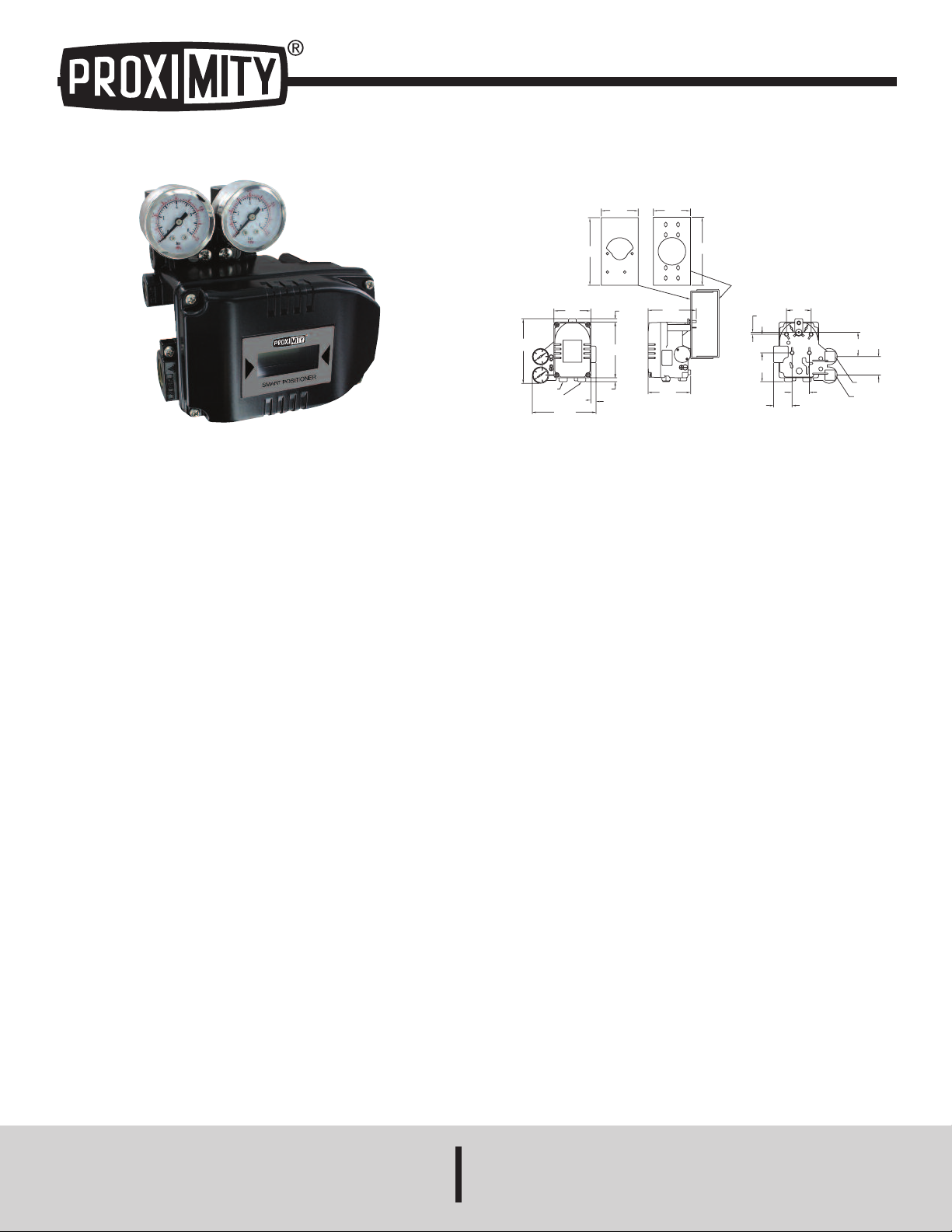
MOUNTING BRACKETS
6-31/64
[164.70]
3-35/64
[90.09]
6-17/32
[165.89]
3-35/64
[90.09]
4-5/64
[103.58]
4-5/8
[117.48]
Bulletin F-98
Series 275 PRECISOR®III Electro-Pneumatic Positioner
Specifications - Installation and Operating Instructions
Series 275 PRECISOR
®
III Electro-Pneumatic Positioner controls
valve stroke accurately using an input signal of 4 to 20 mA from the
controller. In addition, a highly efficient microprocessing operator built
into the product. Performs various powerful functions such as Auto
calibration, PID control, Alarm and Hart®protocol.
FEATURES
• LCD allows user to directly check the positioner condition in the field.
• Endures severe vibration.
• Operates normally regardless of changes in supply pressure during
operation.
• Simple to use auto calibration.
• Easily equipped on small actuators because of its small size.
• Low air consumption reduces operating cost.
• Can be used in low voltage (8.5V), leaving no limitation in controller.
• Variable orifice is applied in case of a small actuator, the hunting is
controlled to the optimum condition during operation.
• HART®communication available for configurating parameters or
monitoring the valve position.
• Analog feedback signal (4 to 20 mA).
• The adjustment of valve characteristics available.
• Specific flow control is available with setting 16 points at users’
command.
• Tight Shut-Close and Shut-Open can be set in the programming
menu.
• PID parameters can easily be adjusted in the field without additional
communicator.
• Split ranges such as 4-12 mA, 12-20 mA are available.
• The positioner can manually actuate the valve or damper.
SPECIFICATIONS
Input Signal: 4-20 mA DC.
Input Impedance: 460 Ohm max @ 20 mA DC.
Material: Aluminum diecasting.
Air Supply: 20 to 100 psi (1.4 to 6.9 bar).
Air Connection: 1/4˝ NPT.
Gage Connection: 1/8˝ NPT.
Conduit Connection: 1/2˝ NPT.
Linearity: ±0.5% of full scale.
Hysteresis: ±0.5% of full scale.
Sensitivity: ±0.2% of full scale.
Repeatability: ±0.3% of full scale.
Air Consumption: below 0.07 scfm (2 LPM) at 20 psig (1.4 bar)
supply.
Flow Capacity: 2.5 scfm (70 LPM) at 20 psig (1.4 bar) supply.
Stroke: 0 to 90°.
Enclosure Rating: NEMA 4X (IP66).
Ambient Temperature: Operating: -40 to 185°F (-40 to 85°C).
Weight: 3.3 lb (1.5 kg).
Lever: 175: 0.39 to 1.57˝ (10 to 40 mm); 275: NAMUR.
DWYER INSTRUMENTS, INC.
P.O. BOX 373 • MICHIGAN CITY, INDIANA 46360, U.S.A. Fax: 219/872-9057 e-mail: info@dwyer-inst.com
Phone: 219/879-8000 www.dwyer-inst.com
HART® is a registered trademark of Hart Communication Foundation
Page 2
page 2
20
450
450
Series 275 Installation
Series 275 is designed for rotary motion valves such as Dwyer
Instruments ball and butterfly valves using rack and pinion, scotch yoke
or complex type actuators whose stem is rotated 90°. Series 275 p ositioners consist of the following components:
1. Series 275 main body
2. Fork lever and lever spring to attach on actuator
3. 1 bracket
4. Four hex bolts M8x1.25P
5. Four M8 plate washers
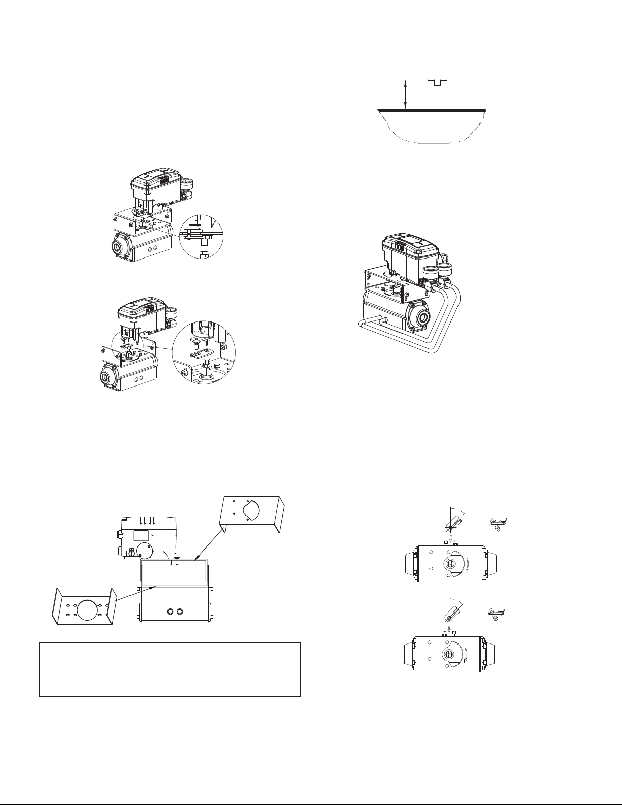
eries 275 installation example
S
eries 275 installation example of fork lever
S
1. Typical actuator stem heights (H) are 0.79, 1.18 and 1.97 inches (20,
30, and 50 mm). After checking H, assemble brackets following
previous guidelines. The bracket is set at 0.79˝ (20 mm) in the
factory.
ctuator Stem (H)
A
Actuator
2. Attach bracket to the actuator using hex bolts. The diameter of the
bracket bolt holes are 0.24˝ (6 mm). Use spring washers or thread
lock compound so the bolts will not be loosened by vibration or
impact. The direction of the bracket varies by operating conditions,
but the normal direction is depicted in the following picture. That is,
when the piping of actuator and Series 275 is as shown in direction
A, the bracket hole and indicator attached on the bottom of the Series
275 main shaft should be mounted in the same direction.
Direction A
Series 275 installation example of Namur shaft
Installing Series 275 with bracket
Series 275 is supplied with a standard bracket. The bracket consists of
two parts and is used with a NAMUR shaft. The bracket is assembled in
the factory based on 0.79˝ (20 mm) of actuator stem height. If the
actuator stem height is higher, such as 1.18˝ (30 mm), or 1.97˝ (50 mm),
reassemble the bracket adjusting to the actuator stem height. Refer to
the table below to check hole positions.
Bracket assembly method by actuator stem height H
Actuator stem
height (H)
20 mm
30 mm
50 mm
A-L
H: 20
H: 30
H: 50
Markings of bolt holes
B-L
H: 20, 30
H: 20, 30
H: 50
A-R
H: 20
H: 30
H: 50
B-R
H: 20, 30
H: 20, 30
H: 50
Attachment direction of bracket and actuator
3. Set the rotation position of actuator stem as the initial zero point,
which is 0% stroke. For a spring return type actuator, the actuator
stem is always rotated to the zero point without supply pressure,
making it easy to check the zero point. If the actuator is doubleacting, check whether the rotation direction of the actuator is
clockwise or counter-clockwise or check the rotation direction of the
actuator using supply pressure.
4. Set the actuator stem as the initial zero point and install a fork lever
as shown in the following picture. Confirm the position of initial zero
point when actuator stem is turned clockwise and counter-clockwise.
Installation angle of fork lever should be about 45 degrees based on
the linear shaft. But the angle is not related to NAMUR shaft.
Counter-Clockwise
Clockwise
Ex) If H is 30 mm, A-L should be locked in H:30 hole, B-L in H:20,30, A-
R in H:30, and B-R in H:20,30 with bolts.
Page 3
page 3
6~11mm
LCD SCREEN
SMART POSITIONER
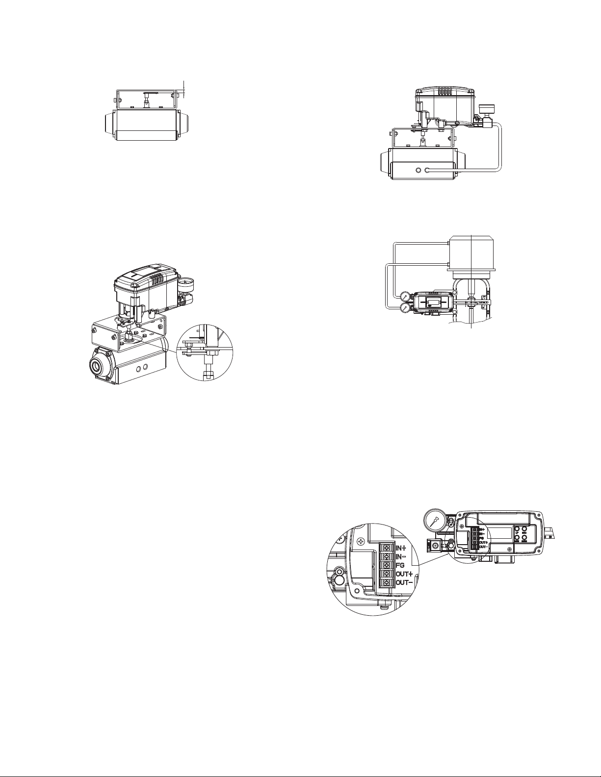
5. Once the fork lever position is set, lock the check nuts on the bottom
of the fork lever by turning clockwise. Set the upper height of the fork
lever to 0.24 to 0.43”(6 to 11 mm) lower than the upper height of the
bracket.
Bracket
ork Lever
F
ctuator
A
Installation position of fork lever
6. Attach Series 275 unit to the bracket. Fix the clamping pin on the
main shaft center of the Series 275 into the hole of the fork lever.
Insert the connection bar attached on the main shaft lever into the
fork lever slot to be locked by the fork lever spring. This is to fit the
main shaft of the Series 275 to the center of the actuator stem. If they
are not fitted correctly, too much force on the main shaft will greatly
reduce product durability.
7. Attach Series 275 base and the bracket with hex bolts and plate
washers. It is best to lock the bracket and Series 275 together by
inserting four bolts after checking the position.
Single Acting Actuator
To operate a single acting actuator, connect OUT1 port to actuator
supply pressure port. Close off the OUT2 port with the supplied 1/4˝
NPT plug.
Piping connection example of Series 275 with single acting actuator
Double Acting Actuator
For the Series 275 double acting type, OUT1 and OUT2 ports are used.
Fitting the pin on the Series 275 main shaft into fork lever hole
PIPING CONNECTION
Note:
1. To prevent ingress of moisture, oil and dust, give careful
consideration to the choice of supply pressure compressor and
piping.
2. It is recommended to attach filter or air filter regulator in front of the
supply port of the Series 275 unit.
Conditions of Supply Pressure
1. Dry air with a dew point that is at least 50°F (10°C) lower than that of
the ambient temperature.
2. Free from solid particles. Result of being passed through 5 micron or
finer filter.
3. Does not contain oil or lubricating oil.
4. Comply with ANSI/ISA-57.3 1975(R1981) or ISA S7.3-1975(R1981).
5. Not used beyond the range of 20 to 100 psi (140 to 689 kPa).
6. Set supply pressure of air filter regulator to 10% higher than
operating pressure of actuator.
Conditions of Pipe
1. Remove foreign objects from inside of pipe.
2. Do not use squeezed or broken pipe.
3. To maintain flow rate of Series 275, use a pipe with inner diameter
greater than 0.24˝ (6 mm) (outer diameter 0.39˝ (10 mm)).
iping connection example of Series 275 with double acting actuator
P
Power Connection
Note:
1. Before connecting terminal, power must be shut off.
2. Use ring type terminal against oscillation, impact, etc.
3. Series 275 positioners use 4 to 20 mA DC for power. Minimum
supply current is 3.2 mA (standard type) and 3.8 mA (HART®type).
Maximum supply current must not exceed 24 mA.
4. In order to protect the Smart Positioner, the ground terminals should
be grounded.
5. Use twisted cable with conductor sectional area at least 0.0019 in
(1.25 mm2), and suitable for 600V as on conductor table of NEC
Article 310. Outer diameter of cable should be 0.25 to 0.39˝ (6.35 to
10 mm). Use shielded wire against electromagnetic waves and
noise.
6. Do not install the cable near equipment such as a high-capacity
transformer or motor.
Terminal plate
2
Piping Connection With Actuator
Series 275 can operate as either single or double acting actuators.
Page 4

page 4
CABLE
CABLE
A
M
A
M
AUTO
MANUAL
Terminal Connection of Current Input Signal
1. Open cover by loosening the four screws on positioner cover.
Terminal connection of input current signal
2. Loosen locking bolts of terminal plate.
3. Insert a cable through the cable connector in the positioner.
4. Use a ring type cable terminal so that it does not come out.
5. Insert terminal bolts in terminal holes of cable and lock them with (+)
terminal and (–) terminals on the terminal plate. Tighten terminal bolts
with 1.1 lbs-ft (15 kfgcm) torque.
6. Be sure not to change the polarity of terminals.
Terminal Connection of Feedback Signal
1. Open cover by loosening the four screws on the positioner cover.
2. Loosen terminal locking bolts of feedback signal terminals.
A/M Switch (Auto/Manual switch)
The A/M switch is located on the bottom of the Series 275 positioners.
When set to auto, supply pressure is transmitted to actuator by the
operation of the positioner. When set to manual, supply pressure of
air filter regulator is transmitted to actuator regardless of positioner.
* When A/M switch is set to manual, make sure that supply pressure
range is not exceeded.
1. Make sure supply pressure is within range.
2. Turn switch clockwise and supply pressure of air filter regulator is
transmitted to actuator.
3. Turn switch counter-clockwise to operate positioner manually.
Variable Orifice
Hunting can occur if the actuator volume is too small. In this case, adjust
the variable orifice using a (-) flathead screwdriver. Hunting is prevented
by reducing the flow rate of supply pressure transmitted to actuator.
aximum Open
M
Terminal connection of transmitter
3. Insert a cable through the cable connector in the positioner.
4. Use a ring type cable terminal so it does not come out.
5. Insert terminal bolts in terminal holes of cable and lock them with (+)
terminal and (–) terminals on the terminal plate. Tighten terminal
bolts with 1.1 lbs-ft (15 kfgcm) torque.
6. Be sure not to change polarity of terminals.
Inner Terminal Connection for Ground
1. The ground is necessary for the safety of the positioner and system.
2. The ground terminals are inside the terminal in the center of the
terminal plate and outside terminal beside outer cable entry. Use any
ground terminal that is available. Resistance must be less than 100
Ohm.
Ground terminal connection
3. For use with inside ground, open cover by loosening the four screws
of positioner cover.
4. In order to maintain the ground connection, use a ring type ground
cable terminal to prevent it from coming out.
Minimum Open
Auto Calibration and Basic Operations
Warning: Since this makes the valve or actuator move, before auto
calibration, the valve must be separated from entire system.
Buttons Operations
Series 275 positioners perform various functions using four buttons. The
position of the buttons is shown below:
Button
<ENTER>
Function
Enter to main menu and sub-menus, save adjusted
parameter values, etc.
<ESC>
<UP> &
Return to previous menu
Move to next menu, change parameter values, etc.
<DOWN>
Page 5
page 5
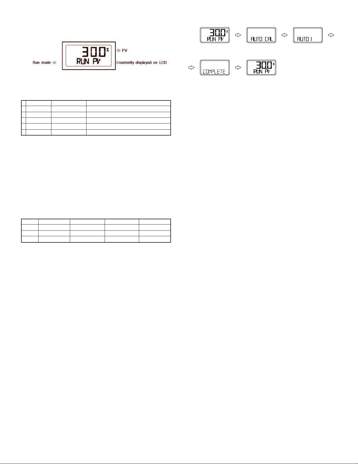
RUN Mode
After connecting power to the positioner, the following is displayed on the
LCD in 6 seconds.
RUN on the bottom line means that the Smart Positioner adjusts valve
stroke based on an outside signal (4-20 mA) and PV refers to the
number on the LCD. In RUN mode, valve stroke is changed according
to input signal.
Run PV
1
Run SV %
2
Run SV mA
3
Run MV
4
Run Vel
5
R
un Err
6
Process Value
Set Value
Set Value
Manipulate Value
Velocity
E
rror
V
alve Stroke (%)
I
nput Signal (0 - 100%)
Input Signal (4 - 20 mA)
Motor/Piezo Valve Manipulate Valve (Digit)
Current Valve Stem’s Velocity (Digit)
Difference between SV and PV (%)
There are six options in RUN mode. In order to change RUN display
modes, hold <ESC> and press <UP> or <DOWN> to scroll through
display options.
First Auto Calibration
First auto calibration is usually used when the positioner has not been
set, such as the initial setting with valve at the valve company or
replacement with other product in the field.
Notice: When the positioner is installed on the valve in the field after
setting, we recommend using AUTO1 calibration rather than AUTO2
calibration. This is because the AUTO 2 calibration parameters have
been factory set to the optimum settings.
RA/DA
x
°
°
AUTO1
AUTO2
AUTO3
Zero Point
°
°
x
End Point
°
°
x
KP, KI, KD
x
°
°
KP
This is a proportion constant value that is correction by error %. If this
value is too big, there can be hunting, even though it finds position by the
input signal. If the value is too small, accuracy gets worse.
KI
This is an integral constant value adding or subtracting the correction
that is corrected error % on the previous correction signal. If this value
is too big, there can be oscillation. If it is too small, the time to find the
exact position increases.
KD
This is a differential constant value adding the previous correction signal
with the changing correction signal by the error % change rate.
RA/DA
Direct acting (DA) or Reverse acting (RA).
Auto Calibration Types
Auto 1 Calibration (AUTO1)
In this mode, all parameters necessary for valve operation are set except
KP, KI, KD. It is used to re-execute calibration by users in the field after
being supplied the postitioner unit whose parameters were set by the
valve company.
1. Push <ENTER> for 6 seconds in RUN mode and AUTO CAL
message should appear.
2. Push <ENTER> and then AUTO1 mode is displayed.
3. Push <ENTER> again at AUTO1 mode and Auto 1 calibration is started.
4. When Auto 1 calibration is done, ‘COMPLETE’ message appears on
the LCD. After 4 seconds the procedure returns to RUN mode and
the valve stroke by current input signal is displayed as a percentage.
(1) Keep pushing
<ENTER> for 6 seconds.
(5) Completed.
(2) Push <ENTER>. (3) Push <DOWN>.
RUN MODE.
Auto 2 Calibration (AUTO2)
All parameters necessary to operate valve are set. This calibration is
used when the positioner is first installed with valve. Refer back to First
Auto Calibration.
Auto 3 Calibration (AUTO3)
All parameters necessary to operate valve are set except zero and end
point. This function is used to re-execute auto calibration without
changing the zero and end point after adjusting them manually.
1. Push <DOWN> at AUTO2 and AUTO3 is displayed.
2. Push <ENTER> and AUTO3 calibration is started. The remaining
procedures of this calibration are the same as other calibrations.
BIAS Calibration
BIAS is the standard value of motor control in the positioner. It is affected
by supply pressure, KP and other values. BIAS should be re-adjusted if
supply pressure or KP is changed, otherwise accuracy will decrease.
1. Press and hold <ENTER> for 6 seconds in RUN mode and AUTO
CAL message should appear.
2. Scroll with <DOWN> button until BIAS mode is displayed.
3. Push <ENTER> and BIAS calibration is started.
4. When BIAS calibration is done, ‘COMPLETE” message appears on
the LCD. After 4 seconds the procedure is returned to RUN mode.
Velocity Calibration (V_0)
This function is used to find the standard value to recognize accurate
valve speed. This value must be correct for KI control to work properly.
To check if velocity value is correct:
1. Push <ESC> button at RUN mode and RUN Vel is displayed.
2. Check the number on the bottom of the screen. Normally, the value
will be between -2 and 2.
3. If value is greater than 5, V_0 calibration is required.
To calibrate V_0:
1. Press and hold <ENTER> for 6 seconds in RUN mode until AUTO
CAL message is displayed.
2. Scroll with <DOWN> button until V_0 mode is displayed.
3. Push <ENTER> and calibration is started.
4. When V_0 calibration is done, ‘COMPLETE’ message appears on the
LCD. After 4 seconds the procedure is returned to RUN mode.
Manual Mode
Manual mode is used to raise or lower the valve stem manually. In this
mode, the valve stroke is adjusted only by operating buttons, not by the
current input signal. This mode does not affect controlling data
registered in the positioner. It only is used to move the valve stem up
and down.
1. Push <ENTER> at RUN mode until AUTO CAL message is
displayed.
2. Push <DOWN> and MANUAL mode is displayed.
3. Push <ENTER> again. Two lines appear on LCD. The upper line
indicates valve stroke by percentage and the lower line indicates
absolute value of inner resistance of the positioner. *MA means that
Manual mode is in operation.
4. Push <UP> or <DOWN> and valve stem moves up or down.
Regardless of RA/DA, if <UP> is pushed, valve stem moves up (in
case of linear valve). If <DOWN> is pushed, valve stem moves down.
Page 6

page 6
In order to make the valve stem move fast, push <ENTER> with
<UP>, or <DOWN>.
Push <UP>.
ush <UP> + <ENTER> at the same time.
P
ush <DOWN>.
P
Push <DOWN> + <ENTER> at the same time.
utton operation for valve stem movement
B
1) Push <ENTER> for 6
(
seconds.
(4) Push <UP>, <DOWN>. (5) Push <ESC>.
2) Push <ENTER>. (3) Push <ENTER>.
(
Valve stem moves up slowly.
alve stem moves up quickly.
V
alve stem moves down slowly.
V
Valve stem moves down quickly.
(6) MANUAL MODE.
5. Push <ESC> and MANUAL mode is displayed.
Parameter Mode (PARAM)
Parameter types
There are four types in Parameter mode: Dead Zone, KP, KI, and KD.
These values are reflected as soon as they are changed, therefore the
appropriate values are found by checking the valve’s motion in real time.
Dead Zone (dEAdZONE)
This is the range of error % that the positioner is not adjusted. Hunting
or oscillation due to friction between the stem and packing is prevented
by this parameter.
KP
This is a proportion constant value that is correcting by error %. If this
value is too big, there can be hunting, even though it finds position by the
input signal. If the value is too small, accuracy gets worse.
KI
This is an integral constant value adding or subtracting the correction
that is corrected error % on the previous correction signal. If this value
is too big, there can be oscillation. If it is too small, the time to find the
exact position increases.
Adjustment of Parameter
Dead Zone (dEAdZONE)
1. Push <ENTER> at RUN mode for 6 seconds and AUTO CAL message
appears.
2. Push <DOWN> twice and PARAM mode is displayed.
3. Push <ENTER> and dEAdZONE mode is displayed.
4. Push<ENTER> again and *EAdZONE message appears.
5. Adjust dEAdZONE value by pushing <UP> or <DOWN>. Adjusted
value is applied immediately without additional operation. Users can
easily check its adjustment by changing the current input signal to the
positioner. Optimum control value is found by adjusting values during
valve operation.
6. Push <ENTER> to save the value. +EAdZONE message appears on
LCD.
(1) Push <ENTER> for 6
seconds.
(4) Push <ENTER>. (5) Push <ENTER>
7) Push <ESC> twice. RUN MODE.
(
(2) Push <DOWN> twice. (3) Push <ENTER>.
fter adjustment by
a
<UP>, <DOWN>.
(6) Push <ESC>.
7. Push <ESC> three times to return to RUN mode.
KP
1-3. Adjustment method and procedure same as dEAdZONE.
4. Push <DOWN> at dEAdZONE mode and KP mode is displayed.
5. Push <ENTER> and *KP message appears on LCD.
6. Adjust KP values with <UP> or <DOWN>. Adjusted value is applied
immediately without additional operation. Users can easily check its
adjustment by changing the current input signal to the positioner.
Optimum control value is found by adjusting values during valve
operation.
7. Push <ENTER> to save the value. +KP message appears on LCD.
8. Push <ESC>.
KD
This is a differential constant value adding the previous correction signal
with the changing correction signal by the error % change rate.
(1) Push <ENTER> for 6
seconds.
(4) Push <DOWN>. (5) Push <ENTER>.
(7) Push <ESC>. (8) Push <ESC> twice. RUN MODE.
(2) Push <DOWN> twice. (3) Push <ENTER>.
9. Push <ESC> twice to return to RUN mode.
(6) Push <ENTER>
after adjustment with
<UP>, <DOWN>.
Page 7

page 7
Feed back signal
(12 ~ 30V)
4 ~ 20 mA
INPUT
KI
1-3. Adjustment method and procedure same as dEAdZONE.
4. Push <DOWN> twice at dEAdZONE mode and KI mode is displayed.
5. Push <ENTER> at KI mode and *KI message appears on LCD.
6. Adjust KI value with <UP> or <DOWN>. Adjusted value is applied
immediately without additional operation. Users can easily check its
adjustment by changing the current input signal to the positioner.
Optimum control value is found by adjusting values during valve
operation. Push <ENTER> to save the value and +KI message
appears on LCD.
7. Push <ESC>.
(1) Push <ENTER> for 6
econds.
s
(4) Push <DOWN> twice. (5) Push <ENTER>.
(7) Push <ESC>. (8) Push <ESC> twice. RUN MODE.
(2) Push <DOWN> twice. (3) Push <ENTER>.
6) Push <ENTER>
(
after adjustment with
<UP>, <DOWN>.
8. Push <ESC> twice to return to RUN mode.
Kd
1-3. Adjustment method and procedure same as dEAdZONE.
4. Push <DOWN> three times at dEAdZONE mode and Kd mode is
displayed.
5. Push <ENTER> at Kd mode and *Kd message appears on LCD.
6. Adjust Kd value with <UP> or <DOWN>. Adjusted value is applied
immediately without additional operation. Users can easily check its
adjustment by changing the current input signal to the positioner.
Optimum control value is found by adjusting values during valve
operation. Push <ENTER> to save the value and +Kd message
appears on LCD.
7. Push <ESC>.
Adjustment of valve zero point (1 to 5) and end point (6 to 10).
1. Push <ENTER> at RUN mode for 6 seconds and then AUTO CAL
mode is displayed. Push <DOWN> three times, the HAND CAL
mode is displayed.
2. Push <ENTER> at HAND CAL mode and PV_ZERO mode is
started.
3. Push <ENTER> at PV_ZERO mode and *PZ mode is started. In this
mode it is available to change valve zero point, and the valve stem
moves automatically to the current zero point. On LCD, valve stroke
is displayed as 0%. +PZ message that indicates edit mode of zero
point and inner value showing current zero point position is also
displayed.
4. Adjust valve stem by pushing <UP> or <DOWN>. When valve stem
has arrived at the desirable zero point, save it with <ENTER>. +PZ
message appears on LCD.
5. Push <ESC> to return to PV_ZERO mode.
(Push <ESC> twice to return to RUN mode.)
6. In order to change valve end point, push <DOWN> at PV_ZERO
mode and PV_END mode begins.
7. Push <ENTER> at PV_END mode and *PE mode is displayed. At
this mode it is available to change valve end point, and the valve
stem moves automatically to current end point. On LCD, the valve
stroke is displayed as 100%. *PE message indicating edit mode of
end point and inner value of end point is also displayed.
8. Adjust valve stem with using <UP> or <DOWN>. When valve stem
arrives at the desirable end point, save it with <ENTER>. +PE
message appears on LCD.
9. Push <ESC> to return to PV_END mode.
10. Push <ESC> twice and RUN mode is displayed.
(Push <DOWN> at PV_END mode to go to TR_ZERO mode).
(1) Push <DOWN>
three times.
(4) Push <ENTER>
after adjustment with
<UP>, <DOWN>.
(2) Push <ENTER>. (3) Push <ENTER>.
(5) Push <ESC>.
(6) Push <DOWN>.
(1) Push <ENTER> for 6
seconds.
(4) Push <DOWN>
three times.
(7) Push <ESC>. (8) Push <ESC> twice. RUN MODE.
(2) Push <DOWN> twice. (3) Push <ENTER>.
(5) Push <ENTER>.
(6) Push <ENTER>
after adjustment with
<UP>, <DOWN>.
8. Push <ESC> twice to return to RUN mode.
HAND CAL
When auto calibration is started, Series 275 positioner set zero points
and end points based on full stroke.
Hand Calibration Types
PV_ZERO: Edit mode to change the zero point of valve.
PV_END : Edit mode to change the end point of valve.
TR_ZERO : Edit mode to change the zero point of transmitter.
TR_END: Edit mode to change the end point of transmitter.
(7) Push <ENTER>. (8) Push <ENTER> after
(10) Push <ESC> twice.
adjustment with <UP>,
<DOWN>.
RUN MODE.
(9) Push <ESC>.
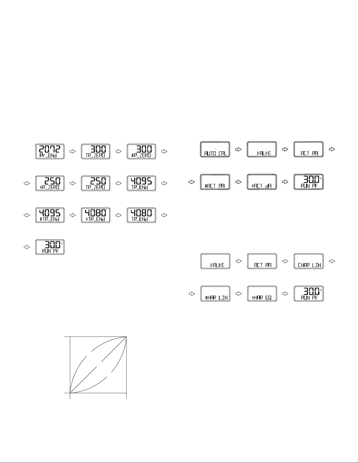
Adjustment of zero point (1 to 4), end point (5 to 9) of transmitter.
If valve zero point and end point are changed, transmitter is also
changed automatically. Usually there is no need for the transmitter zero
point and end point to be adjusted by users, but if transmitter output
signal is unstable, transmitter zero point and end point should be
adjusted. The ammeter showing feedback signal is necessary and the
connection should be done as shown.
Page 8
page 8
100%
Strok
0
4
20
mA
Quick Open
Linear
EQ%
1. Push <DOWN> at PV_END mode and then TR_ZERO mode is
displayed.
2. Push <ENTER>. *R_ZERO mode is started and at this mode users
can adjust the zero point of the transmitter. Valve stem is moved to
zero point automatically.
3. Push <UP> or <DOWN>. The number on the LCD is changed and
the measured current value is changed accordingly on an ammeter
equipped outside. Adjust it to be 4mA and push <ENTER> to save
it. +R_ZERO message is displayed.
4. Push <ESC>. TR_ZERO mode is displayed.
5. Push <DOWN> at TR_ZERO mode. Then TR_END mode is
displayed.
(Push <ESC> twice to return to RUN Mode.)
6. Push <ENTER>. *TR_END mode is started and at this mode users
can adjust the end point of transmitter. Valve stem is moved to the
end point automatically.
7. Adjust measured current value to be 20 mA on ammeter with <UP>
or <DOWN> buttons. Push <ENTER> to save it. +R_END message
appears.
8. Push <ESC>. TR_END mode is displayed.
1) Push <DOWN>. (2) Push <ENTER>. (3) Push <ENTER>
(
(4) Push <ESC>. (5) Push <DOWN>.
after adjustment with
UP>, <DOWN>.
<
(6) Push <ENTER>.
Tight Shut Open (TSHUT OP)
This allows the user to fully open valve at any value around the 20 mA
current input signal.
Tight Shut Close (TSHUT CL)
This allows the user to completely close valve at value around 4 mA input
signal from outside.
Split Range Control (SPLIT)
This allows the user to control entire stroke with input signals of 4 to 20
mA, 4 to 12 mA or 12 to 20 mA.
Adjustment of Acting Type (ACT)
1. Push <ENTER> at RUN mode for six seconds and then AUTO CAL
mode is displayed. Push <DOWN> four times to go into VALVE
mode.
2. Push <ENTER> and ACT RA (in case of RA) is displayed.
3. Push <ENTER> again, then *ACT RA is displayed.
4. Adjust to *ACT DA by pushing <UP> or <DOWN> and save it with
<ENTER>. +ACT DA message appears.
1) Push <DOWN>
(
four times.
4) Push <ENTER>
(
fter adjustment with
a
<UP>, <DOWN>.
2) Push <ENTER>. (3) Push <ENTER>.
(
5) Push <ESC>
(
hree times.
t
UN MODE.
R
5. Push <ESC> three times to return to RUN mode.
7) Push <ENTER>
(
after adjustment with
<UP>, <DOWN>.
RUN MODE.
8) Push <ESC>. (9) Push <ESC> twice.
(
9. Push <ESC> twice to return to RUN mode.
Valve Mode
This mode adjusts the various characteristics.
Action Type (ACT)
It can be set to Direct Action (DA) or Reverse Action (RA).
Characteristics (CHAR)
It is set Characteristics. There are three types of valve characteristics:
Linear (LIN), EQ% (EQ), and Quick Open (QO). The following is the
example of the three characteristic curves.
Adjustment of Characteristics (CHAR)
1. Push <ENTER> at VALVE mode and then push <DOWN>. CHAR
LIN (in case of linear characteristics) mode is displayed.
2. Push <ENTER>. *HAR LIN mode is displayed and characteristics
can be adjusted at this mode.
(1) Push <ENTER>. (2) Push <DOWN>. (3) Push <ENTER>.
(4) Push <ENTER>
after adjustment with
<UP>, <DOWN>.
(5) Push <ESC>
three times.
RUN MODE.
3. Adjust Characteristics (ex: EQ) by pushing <UP> or <DOWN> and
save it with <ENTER>. +HAR EQ is displayed.
4. Push <ESC> three times to return to RUN mode.
User Characteristics (USER SET)
When a specific characteristic is needed but not included in the above
characteristics, the user can make a specific characteristic curve by
choosing 16 points voluntarily according to field conditions and the user’s
need.
Page 9

page 9
Adjustment of User Characteristics (USER SET)
1. Push <ENTER> at VALVE mode and ACT RA or ACT DA is
displayed.
2. Push <DOWN> twice, then USER SET mode is started.
3. Push <ENTER>. *P0 SET mode is displayed. In this mode, users
can adjust the first point of characteristic in 16 points. The number
on the LCD is the valve stroke percentage set to P0.
4. Adjust valve stroke percentage using <UP> or <DOWN>.
5. Save it with <ENTER>. While P0 value is being saved, *P1 SET
mode is displayed.
6. *P1 SET mode is used to adjust the second point of characteristic in
16 points. Adjustment method is the same as *P0 SET mode.
7. Save the valve stroke percentage from P2 to P15 in the same way.
8. After adjustment of valve stroke percentage at *P15 SET mode, save
it with <ENTER>.
9. +SER SET is displayed. Sixteen points of valve stroke percentage
are all set. Push <ESC> three times to return to RUN mode.
(1) Push <ENTER>. (2) Push <DOWN> twice. (3) Push <ENTER>.
4) Adjust with <UP>,
(
<DOWN>.
(7) Set P2-P15. (8) Push <ENTER>. (9) Push <ESC>
5) Push <ENTER>. (6) Set P1.
(
hree times.
t
Adjustment of Tight Shut Close (TSHUT CL)
1. Push <ENTER> at VALVE mode and ACT RA or ACT DA is
displayed. Push <DOWN> four times at this mode. TSHUT CL is
displayed.
2. Push <ENTER>. *SHUT CL mode is displayed and in this mode
users can set stroke at the time of Tight Close. Initial setting is done
as 0.3%. 0% means cancellation of this function. Adjust the value
(ex: 0.5%) by pushing <UP> or <DOWN> and save it by pushing
<ENTER>. +SHUT CL is displayed.
(1) Push <DOWN>
four times.
4) Push <ESC>
(
three times.
(2) Push <ENTER>. (3) Push <ENTER>
UN MODE.
R
after adjustment with
UP>, <DOWN>.
<
3. Push <ESC> three times to return to RUN mode.
Adjustment of Split Range (SPLIT)
1. Push <ENTER> at VALVE mode and ACT RA or ACT DA is
displayed.
2. Push <DOWN> five times and SPLIT mode is displayed. The
numbers on the LCD are the range of current signal input to the
positioner. 4 to 20 mA current signal is set as the standard.
3. Push <ENTER>. *SPLIT mode is displayed and input signal range
can be adjusted. Adjust input signal range with <UP> or <DOWN>
and save it with <ENTER>.
4. +SPLIT mode is displayed while saving adjusted range. Push
<ESC> three times to return to RUN mode.
UN MODE.
R
Adjustment of Tight Shut Open (TSHUT OP)
1. Push <ENTER> at VALVE mode and ACT RA or ACT DA is
displayed. Push <DOWN> three times at this mode. TSHUT OP is
displayed.
2. Push <ENTER>. *SHUT OP mode is displayed and in this mode
users can set stroke at the time of Tight Open. Initial setting is done
as 100%, which means cancellation of this function. Adjust the
value (ex: 95.0%) by pushing <UP> or <DOWN> and save it with
<ENTER>. +SHUT OP is displayed.
3. Push <ESC> three times to return to RUN mode.
(1) Push <DOWN>
three times.
(4) Push <ESC>
three times.
(2) Push <ENTER>. (3) Push <ENTER>
RUN MODE.
after adjustment with
<UP>, <DOWN>.
(1) Push <ENTER>. (2) Push <DOWN>
(4) Push <ENTER>
after adjustment with
<UP>, <DOWN>.
five times.
(5) Push <ESC>
three times.
(3) Push <ENTER>.
RUN MODE.
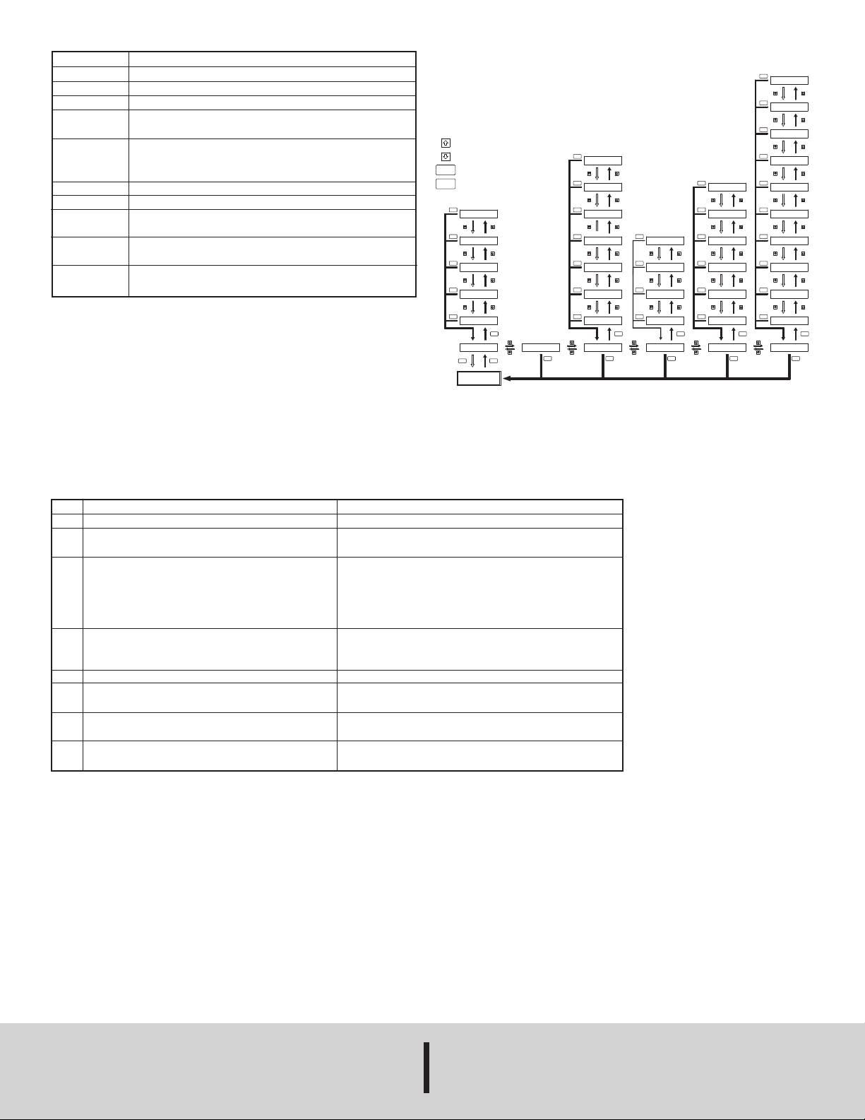
VIEW Mode
This mode provides users with various information about the Series v275
positioners. In this mode, users can change the valve stroke types
displayed on LCD to % or numbers. Refer to the next table for
information and description displayed on VIEW mode.
1. Push <DOWN> at AUTO CAL mode and VIEW mode is displayed.
2. Push <ENTER> at VIEW mode, then information mode is started.
(1) Push <DOWN>
four times.
(4) Push <ESC>. RUN MODE.
(2) Push <ENTER>. (3) Check data with
<UP>, <DOWN>.
3. Check information by using <UP> or <DOWN> and push <ESC>.
4. Push <ESC> again to return to RUN mode.
Page 10
page 10
Used timeUser Set
E
NT
:
Enter button
Manual Mode
Auto 2
Auto cal
RUN Mode
ENT
(5 sec)
ESC
ESC
Auto 1
ENT
B
IAS
Auto 3
ESC
ESC
V
_O
ESC
ESC
Hart ver.CharacterK P
End point
ViewValveHand calParameter
ESCESC ESC ESCESC
ESC
Start point
Dead Zone
ESC ESC
ENT ENT
ESC
Sof ver.
RA / DA
ENT ENT
B
IAS
Tight shut onTR end point
K
D
Tight shut oTR start point
K I
ESC ESCESC
ESC ESCESC
Polling Add
ESC
ESC
ESC ESCESC
ESC
I value
Split control
ESC
ESC
:
Up button
E
SC
: Down button
:
Esc button
Error code
Full close time
ESC
Full open time
ESC
ESC
View method
ESC
ESC
ESC
ESC
ESC
K I_
K
P_
ESC
K D_
Options
VERSION
HART V
POL AddR
bIAS VI
Description
Main software version
®
HART
protocol version
Channel address used in HART®protocol
BIAS value necessary to motor control (This variable
is used only by manufacturer)
OY Od
Total using time
But if the product is used less than one minute from
power-on to power-off, it is not added to total time
FULL_OP
FULL_CL
VM NOR
Full Open Time (sec) of valve
Full Close Time (sec) of valve
Display type of valve stroke on LCD
Either % or number is available
Erro
Error or warning code currently occurred.
Refer to the Code table.
VALUE 1
Currently controlled I value (This variable is used
only by manufacturer)
Information checked on VIEW mode
Error and Warning Code
If there are any problems during the Series 275 positioner operation, you
can check the error and warning code at VIEW mode as follows:
Error Code
This code is displayed when the Series 275 positioner control becomes
impossible. Code C, D applies.
Warning Code
This code is displayed when the positioner control is available but there
is a possibility of malfunction or low accuracy. Code B, F, G, H applies.
Description and Cause
Code
None
A
The range of Pv Span – Pv Zero is less than 500.
B
Operating angle of feedback is too small.
More than 10% error is continued over more than
C
one minute.
-There’s no valve movement.
-Valve friction is getting too big.
-Setting pressure of regulator is changed.
I value is at I max or min limit.
D
-Valve friction has changed.
-Setting pressure of regulator has changed.
None
E
Full Open, Close time is less than one second.
F
-Actuator size is too small.
Pv is set lower than 100.
G
-Operating angle of feedback lever is set too big.
Pv is greater than 4000.
H
-Operating angle of feedback lever is set too big.
Error/Warning code
MAINTENANCE
The Series 275 PRECISOR®III Positioner is not field serviceable and
should be returned if repair is needed (field repair should not be
attempted and may void warranty). Be sure to include a brief description
of the problem plus any relevant application notes. Contact customer
service to receive a return goods authorization number before shipping.
Copyright 2013 Dwyer Instruments, Inc. Printed in U.S.A. 6/13 FR# R2-443558-00 Rev. 2
DWYER INSTRUMENTS, INC.
P.O. BOX 373 • MICHIGAN CITY, INDIANA 46360, U.S.A. Fax: 219/872-9057 e-mail: info@dwyer-inst.com
Measures
None
-Increase operating angle of feedback lever and
execute AUTO1 calibration.
-Check the pressure setting of air filter regulator.
Adjust it to recommended pressure
Execute BIAS calibration
-Check the pressure setting of air filter regulator.
Adjust it to recommended pressure
Execute BIAS calibration
None
-Use variable orifice.
-Replace actuator to bigger one.
-Adjust operating angle of feedback lever to be smaller
and execute AUTO1 calibration.
-Adjust operating angle of feedback lever to be smaller
and execute AUTO1 calibration.
Phone: 219/879-8000 www.dwyer-inst.com
 Loading...