

Page 1
INSTALLATION INSTRUCTION
FLAIR - dwelLED™
PD-52214
WARNING
IMPORTANT: NEVER attempt any work without shutting o the electricity.
- Read all instructions before installing.
- System is intended for installation by a qualied electrician in accordance with the National Electrical Code and local
regulations.
- Go to the main fuse box, or circuit breaker. Place the main power switch in the “OFF” position and unscrew the fuse(s) or
switch ”OFF” the circuit breaker switch(es) that control the power to the xture or room that you are working on.
- Place the wall switch in the “OFF” position.
CAUTION
- All parts must be used as indicated in these instructions. Do not substitute any parts, leave parts out, or use any parts
that are worn out or broken. Failure to follow this instruction could invalidate the ETL/CETL listing of this xture.
CAUTION When handling the xture, do not apply pressure to the LEDs. Hold the xture by the base only.
AVERTISSEMENT
IMPORTANT : Coupez l’électricité avant TOUTE manipulation.
- Lisez toutes les instructions avant d’installer.
- Système est destiné à être installé par un électricien qualié en conformité avec le code national de l’électricité et les
règlements locaux.
- Accédez au panneau central de disjoncteurs ou de fusibles de votre demeure et placez l’interrupteur principal en posi
tion d’arrêt (« OFF »).
- Placez l’interrupteur mural en position d’arrêt (« OFF »).
MISE EN GARDE
- Toutes les pièces doivent être utilisées tel qu’il est indiqué dans ces instructions. Ne remplacez pas les pièces, n’en
laissez pas de côté et ne les utilisez pas si elles sont usées ou brisées. Le non-respect de ces instructions peut annuler
l’homologation ETL/CETL du luminaire. MISE EN GARDE Ors de la manipulation de l’appareil, ne pas appliquer de pression
à la LED, tenir l’appareil par la seule base.
ADVERTENCIA
IMPORTANTE: NUNCA intente hacer trabajos sin desconectar el suministro eléctrico.
- Lea y comprenda todas las instrucciones e ilustraciones por completo antes de proceder con el ensamblaje e insta
lación de esta lámpara.
- Sistema está disenado para ser instalado por un electricista calicado, de acuerdo con el código eléctrico nacional
y las normas locales.
- Diríjase a la caja de fusibles o a la caja del interruptor de circuito principal en su hogar. Coloque el interruptor de ali
mentación principal en la posición “OFF” (APAGADO).
- Coloque el interruptor de la pared en la posición “OFF” (APAGADO).
PRECAUCIÓN
- Todas las piezas deben usarse como lo indican estas instrucciones. No reemplace las piezas, noomita piezas durante la
instalación ni utilice piezas gastadas o rotas. El incumplimiento de esta indicación podría invalidar la calicación
ETL/CETL esta lámpara. PRECAUCIÓN Al manipular el aparato, no aplique presión a los LED, mantenga el aparato en la
base sólo.
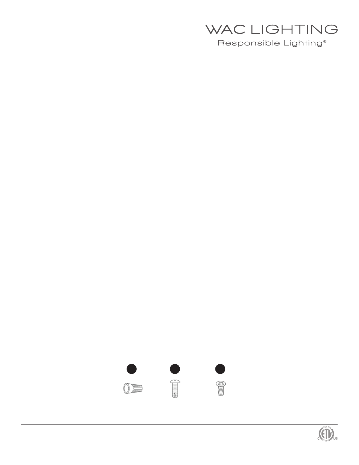
HARDWARE
WAC Lighting
www.waclighting.com
Phone (800) 526.2588 • Fax (800) 526.2585
WAC Lighting retains the right to modify the design of our products at any time as part of the company's continuous improvement program. AUGUST, 2014
C1 E1 B1
Wire
Connector
Qty: 5
Headquarters/Eastern Distribution Center
44 Harbor Park Drive • Port Washington, NY 11050
Phone (516) 515.5000 • Fax (516) 515.5050
Junction Box
Screw
Qty: 2 + 1 Extra
Mounting
Screw
Qty: 2 + 1 Extra
Western Distribution Center
1750 Archibald Ave • Ontario, CA 91761
Phone (800) 526.2588 • Fax (800) 526.2585
Page 2
INSTALLATION INSTRUCTION
FLAIR - dwelLED™
PD-52214
PREPARATION
1. Shut o the power at the circuit breaker and
remove existing xture, including the mounting hardware.
2. Carefully unpack your new xture and lay out all the parts
on a clear area. Be careful not to lose any small parts
necessary for installation.
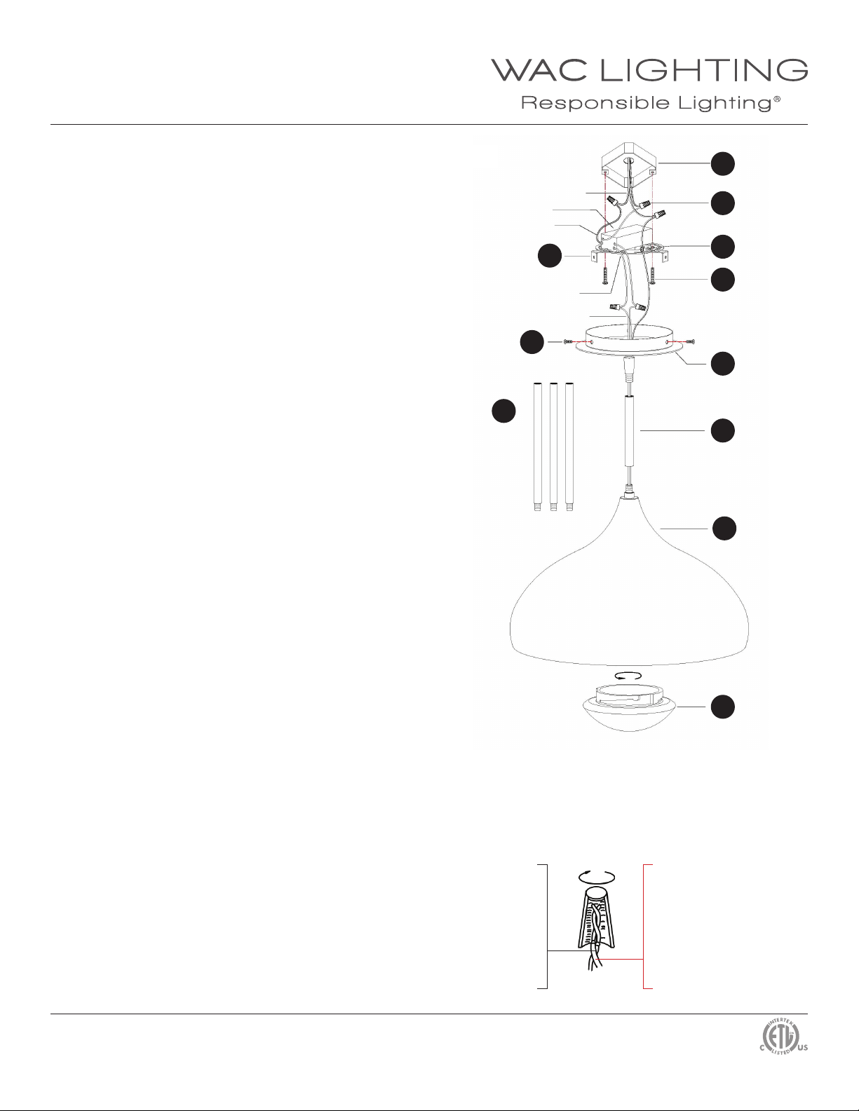
MOUNTING THE FIXTURE (Fig. 1)
3. Choose stem sections (G1) needed to hang the pendant
at desired height.
4. Lead the xture wire through the stems (G1) and canopy
(F1). Connect the xture (H1) and the stems to the canopy (F1).
5. Leave the xture wires at least 6” long from canopy (F1)
center. Cut the extra wires. Carefully strip the wires using a wire
stripper (not provided).
CONNECTING THE WIRES (Fig. 2)
6. Connect the driver input wires with junction box wires as
shown in Fig. 2, making sure the wire connectors (C1) are secured. Tuck wires carefully inside the junction box (B1).
FIG.1
Mounting
plate
screws
Junction Box wire
Driver
Input
D1
B1
G1
Stem
Screws
B1
Wire connectors
C1
Green screws
J1
Junction box screws
E1
Canopy
F1
Stem
G1
Glass
H1
7. Mount the driver onto the mounting plate (D1) using the
provided double sided adhesive tape. Feed driver output wires
through mounting plate holes. Fasten the mounting plate (D1)
to the junction box (B1) using junction box screws (E1). The
side of the mounting plate marked “GND” must face out.
*Requires Driver to be recessed within the junction box.
8. Connect the driver output wires with the xture wires as
shown in Fig. 2, red (+) to red (+) and black (-) to black (-),
making sure that all wire connectors are secured.
Fixture and junction box ground wires should be connected
to mounting plate using green screw provided. Tuck wires
carefully inside the junction box (A1).
9. Place the canopy (F1) over the mounting plate (D1) and
secure them using the set screws (B1).
10. Twist lock the glass diuser (I1) into the xture inside (H1).
FIG.2
Fixture Wires
Black or
Smooth
Fixture Wires
White or
Ribbed
Fixture Wires
Bare Copper
(Ground)
Glass diuser
I1
House Wires
Black
(Hot)
House Wires
White
(Neutral)
House Wires
Green or Bare Copper
(Ground)
WAC Lighting
www.waclighting.com
Phone (800) 526.2588 • Fax (800) 526.2585
WAC Lighting retains the right to modify the design of our products at any time as part of the company's continuous improvement program. AUGUST, 2014
Headquarters/Eastern Distribution Center
44 Harbor Park Drive • Port Washington, NY 11050
Phone (516) 515.5000 • Fax (516) 515.5050
Western Distribution Center
1750 Archibald Ave • Ontario, CA 91761
Phone (800) 526.2588 • Fax (800) 526.2585
 Loading...