


HDI
Heavy Duty
Industrial
DV Systems Inc.
- Canada
DV Systems
Ltd. - US
(‘HDI’)
Air Compressor
Installation,
Maintenance,
And
Service Data
HDI-03-W
Mar ‘15
Contents: Page:
Quick Start 2
Safety Precautions 3
Preventative Maintenance Schedule 4
Unpacking and Inspection 5
Compressor Terminology 6
Installation – Mechanical 7
Lubrication 8
Installation – Electrical 9-10
Start-up Procedures 11
Compressor Unit Accessories 12-14
Compressed Air System Design 15-16
Refrigerated Air Dryers 17-18
Compressed Air Filter Assemblies 19
Trouble-Shooting Guide 20-23
DV Systems Limited Warranty 24-25
Warranty Registration 26
490 Welham Road
Barrie, ON
L4N 8Z4
Tele: (705) 728-5657
Fax: (705) 728-4974
Please read this manual before
installing or using your Air
Compressor Unit. It contains
valuable information that will
help in the receiving,
installation, use, and
maintenance of the Unit.
Please keep this manual in a
safe place for future reference.
All of the information, policies, and
procedures in this reference manual apply
exclusively to DV Systems.
Web: www.dvcompressors.com
Email: sales@dvcompressors.com
128-B Talbert Road
Mooresville, NC
28117
Tele: (704) 799-0046
Fax: (704) 799-0355
- 1 -
Mechanical Installation.
Pump Rotation.
Note:
(Refer to Page 7)
HDI-03-W
Mar ‘15
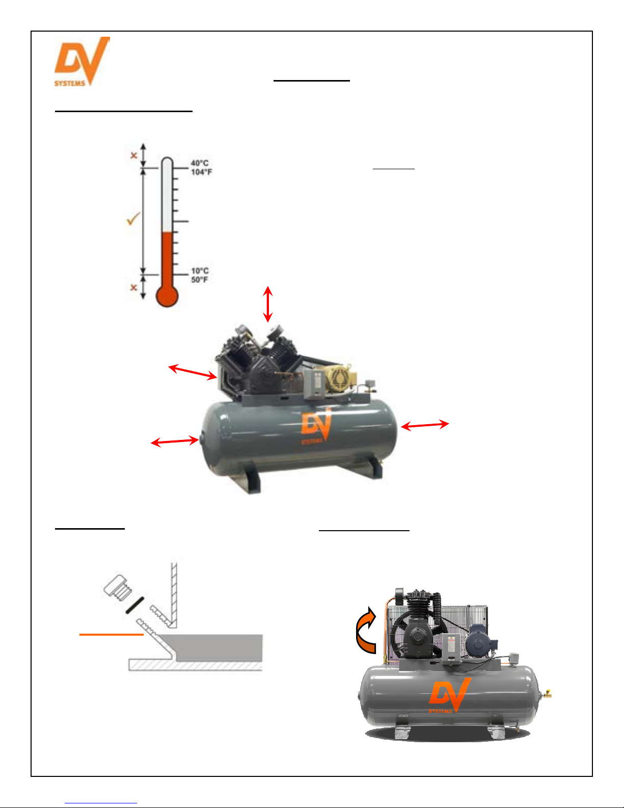
Quick Start
The Unit should be located in a dry, clean,
cool, dust free, and well ventilated area.
Allow a minimum 18” behind the BeltGuard and
around the Unit.
The ambient temperature should be between
10°C and 40°C (50°F and 104°F).
Ensure that the floor under the Unit is smooth,
level and capable of bearing the weight of the
Compressor.
If installed in a compressor room, ensure that
the room is adequately ventilated
24”
Lubrication.
(Refer to Page 8)
Proper Oil
Level
18”
18”
(Refer to Page 10)
18”
The arrow below
indicates the correct
rotation of the Flywheel.
The Unit is shipped with ‘PR20’ 20
Weight Compressor Oil in the Pump.
Verify the proper level as indicated
above before starting.
- 2 -
HDI-03-W
Mar ‘15
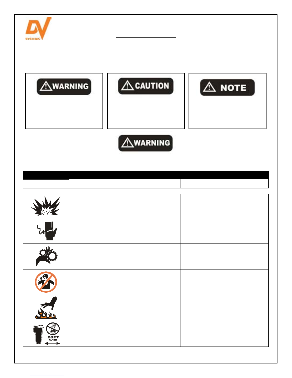
Safety Precautions
In order to operate the Compressor Unit safely and correctly, we have opted to use the following symbols to make
you aware of important points. These points relate to user safety and preventing equipment problems. Please pay
close attention to these sections.
Important safety Information.
A hazard that may cause
serious injury or loss of life.
Important information that
indicates how to prevent
damage to equipment, or how
to avoid a situation that may
cause minor injury.
Information that you should
pay special attention to.
The following hazards may occur during the normal use
of the equipment. Please read the following chart.
Area: Hazard: Safeguards:
What to look for: What may occur if precautions are not observed. How to avoid the hazard.
Tampering with the Unit while under full or partial
pressure may cause an explosion.
As the Unit starts and stops automatically, serious
injury may result from working on the Unit with the
power still in the on position.
As the Unit starts and stops automatically, do not
come into contact with moving parts.
Air compressed by the Unit is not suitable for
inhaling. It may contain vapours harmful to your
health.
Relieve all pressure from the Unit
before attempting any repair or
maintenance work.
Shut off all power to the Unit before
attempting any repair or maintenance
work.
Shut off all power to the Unit before
attempting any repair or maintenance
work.
Never directly inhale compressed air
produced by the Compressor.
The Compressor Pump, Motor, and Tubing
become hot when running. Touching these areas
may cause severe burns.
As the electrical components on the Unit are
General Purpose, there is a potential for explosion
should vapours be present in the area.
Never touch the Pump, Motor, or
Tubing during or immediately after
operation.
The Compressor must be a minimum
of 20 feet (6.1 meters) from any source
of potentially explosive vapours.
- 3 -

HDI-03-W
Insist
on Genuine DV
Preventative Maintenance Schedule
Noted below are general maintenance guidelines which must be followed and documented, this in accordance
with the DV Systems Warranty. It is based on an approximate Compressor usage of 30 hours per week. If your
particular application varies from this, please adjust accordingly.
Drain moisture from Air Receiver
Check oil level and top up as required
Replace Air Filter 1
Replace Oil (mineral) 2
Check condition/alignment of Belts/Pulley
Check Safety Valves
Check that Unit unloads when shutting down
Clean and/or blow dust/dirt off Unit
Replace Oil (synthetic) 3
Check lubrication of Motor
Inspect Valve Assemblies in Cylinder Head(s)
Inspect Check Valve
Inspect Pressure Gauge
Replace Belts 4
Replace Valve Discs and Springs 5
Replace CPR Unloader Kit 6
Replace Pressure Switch
Replace Safety Valves on Pump and Tank
Replace Pressure Gauge
Notes: 1. Air Filters are available separately or in a Maintenance Kit. Consult your Pump bulletin.
When servicing the Air Compressor, shut off all power to the Unit, and drain the Tank
of air pressure. Always re-install the Beltguard after adjusting the Belts or Pulleys.
Systems parts and kits
when maintaining your
Compressor Unit and
Pump.
2. Mineral Oil is available separately or in a Maintenance Kit. Consult your Pump bulletin.
3. Synthetic Oil is available separately or in a Maintenance Kit. Consult your Pump bulletin.
4. Belts are available through your local DV Systems Distributor.
5. Valve Discs and Springs are available separately or in a Kit. Consult your Pump bulletin.
6. The CPR Unloader Assembly and Kit is noted in your Pump bulletin.
Daily
Weekly
Notes
Normal Maintenance
Monthly
Every 3 Months
Every 6 Months
st
Year Maint.
Year Maint.
Year Maint.
nd
1
items at left to be carried out
regularly throughout the years.
rd
2
‘Normal Maintenance’
Year Maint.
th
3
4
Mar ‘15
Year Maint.
th
Year Maint.
th
5
6
Year Maint.
th
7
- 4 -

HDI-03-W
Mar ‘15
Unpacking and Inspection
Each DV Systems Air Compressor is carefully tested and
inspected before shipment. Though every attempt is made to
ensure the safe and complete shipment of our product, freight
damage or misplacement of goods may occur.
Shipments of DV Systems products are the property of the
Consignee when the products leave our facility. DV Systems Inc.
is not responsible for any damages or shortages caused to the
product after it has left our shipping dock.
It is the responsibility of the receiver of the goods, either the Distributor or Customer, to ensure that the product
has been shipped in full, and has arrived in suitable condition. Damage to the product may not be visible at time
of off-loading, but may only become apparent upon unpacking or start-up.
Some areas to initially check are as follows:
a) Check for damage to the crating and/or packaging.
b) Check for damage to the Beltguard.
c) If the BeltGuard appears damaged, remove the Guard and turn the Flywheel by hand to ensure the
Crankshaft has not been bent, and the Belt drive is properly aligned and free of distortion.
d) Check the Air Tank thoroughly for possible damage
Should there be damage to the product or shortages in shipment:
1) Stop any further unpacking or operation of the product.
2) Make note of the problem on the Freight Bill, should it concern a shortage or visible
damage to the product.
3) Should the damage be noticed only after the product has been received, contact the
transport company immediately to file a claim.
Depending on the problem, it may be wise to photograph the damage. Also, it may
be wise to discuss with the carrier representative the time allotted to give notice of loss
or damage to the product; there may be guidelines which limit timeframes of same.
4) Do not attempt further unpacking or operation of the product. Also, do not discard
any packing material used.
5) A Loss or Damage Claim must be submitted to the carrier and supported by the
following documents:
- Copy of Freight Bill of Lading
- Copy of the Invoice and Estimate to repair, in case of damage
- Damage Report
- Copy of photos, if applicable
- 5 -

HDI-03-W
Compressor Pump
I
ntercooler
Beltguard
Aftercooler Tube
Pressure Switch
Check Valve
Air Receiver (Tank)
Magnetic Starter
Drain Valve
Ball Valve
Mar ‘15
Compressor Terminology
Please refer to the picture below, as it identifies the major components of a typical Piston Air Compressor Unit
and their function. (Some Units may vary slightly from this design, eg. gas powered or base mounted Units.)
Allows the compressed air
to cool as it transfers from
the Pump to the Tank.
Allows the compressed air
to enter the Tank, but
prevents it from flowing
back out.
Stores the compressed air.
Compresses the air.
An electrical device which
receives a signal from the
Pressure Switch and
allows power to flow to the
Motor.
Allows the compressed air to
cool while it transfers between
the low and high pressure
Cylinder.
Protects personnel from the
moving parts of the Flywheel,
Pulley, and Belts.
Allows the Customer to
drain moisture from the
Tank.
Pump Components
Please refer to the Compressor Pump Service Bulletin provided
with your Unit to identify the part numbers, location, and
quantities for your particular Pump model.
Electric Motor
A Switch which starts and
stops the Unit at a
predetermined minimum
and maximum pressure.
Pressure Gauge
Reflects Tank pressure.
Safety Valve
Protects the Tank if
pressure is too high.
Discharge/outlet from
Tank.
- 6 -
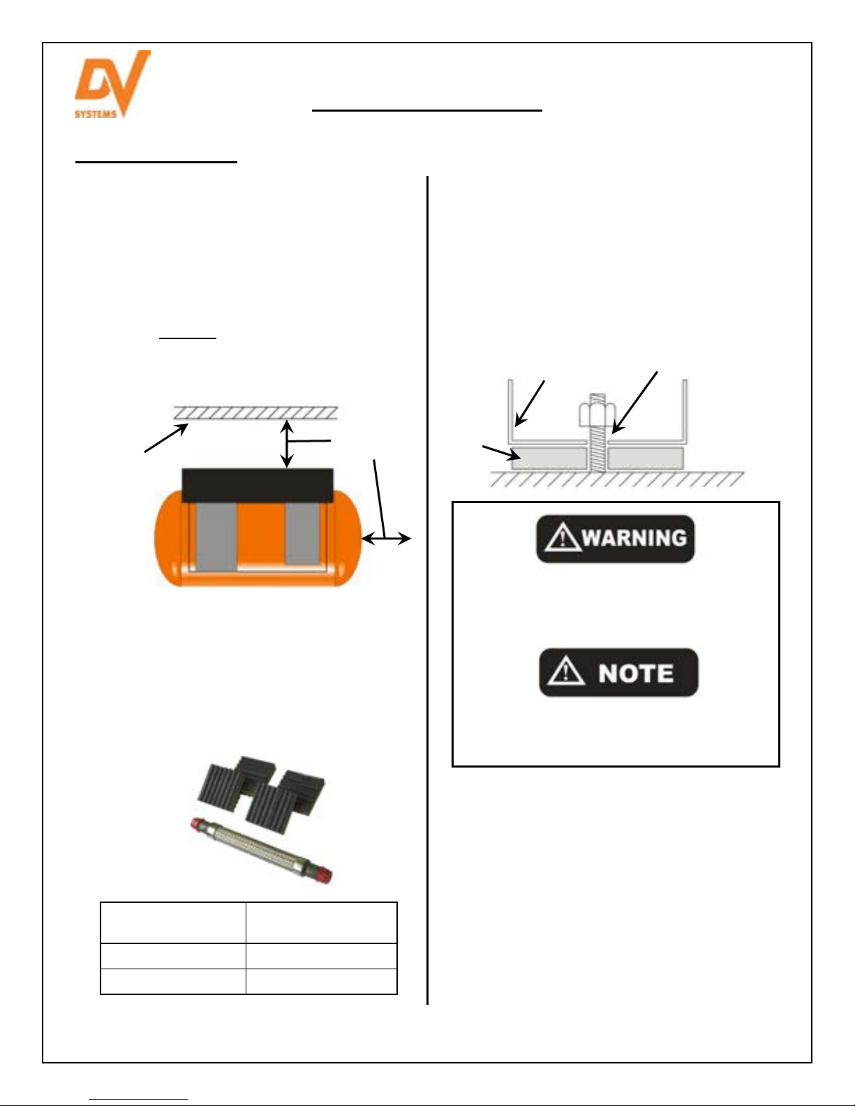
Installation – Mechanical
Location of the Unit.
Items to consider when installing the Unit are as
follows:
The Unit should be located in a dry, clean, cool,
dust free, and well ventilated area. If possible, the
Compressor should be located in a separate
room or area, away from the general operations
of the shop.
Allow a minimum of 18” around and 24” above
the Unit, this being for both the proper ventilation
of the Unit and ease of servicing.
Building
Wall, etc
Beltguard
Compressor
Ensure that the floor under the Unit is smooth,
level and capable of bearing the weight of the
Compressor. The Compressor must sit squarely
on the floor.
DV Systems has available Installation Kits which
include (4) Vibration Isolator Pads and (1)
Stainless Steel Flex Hose.
Systems
DV
Installation Kit
‘HDI’ Compressor
Horsepower
IK515 5 to 15 HP
IK2530 25 and 30 HP
18” (0.5 m)
minimum
(& Opposite)
HDI-03-W
Mar ‘15
If installing the Unit on a mezzanine, ensure
that the structure can safely support the weight
of the Unit. As well, the sound level of the Unit
may increase due to the harmonics created by
the structure; use Vibration Pads to lessen this.
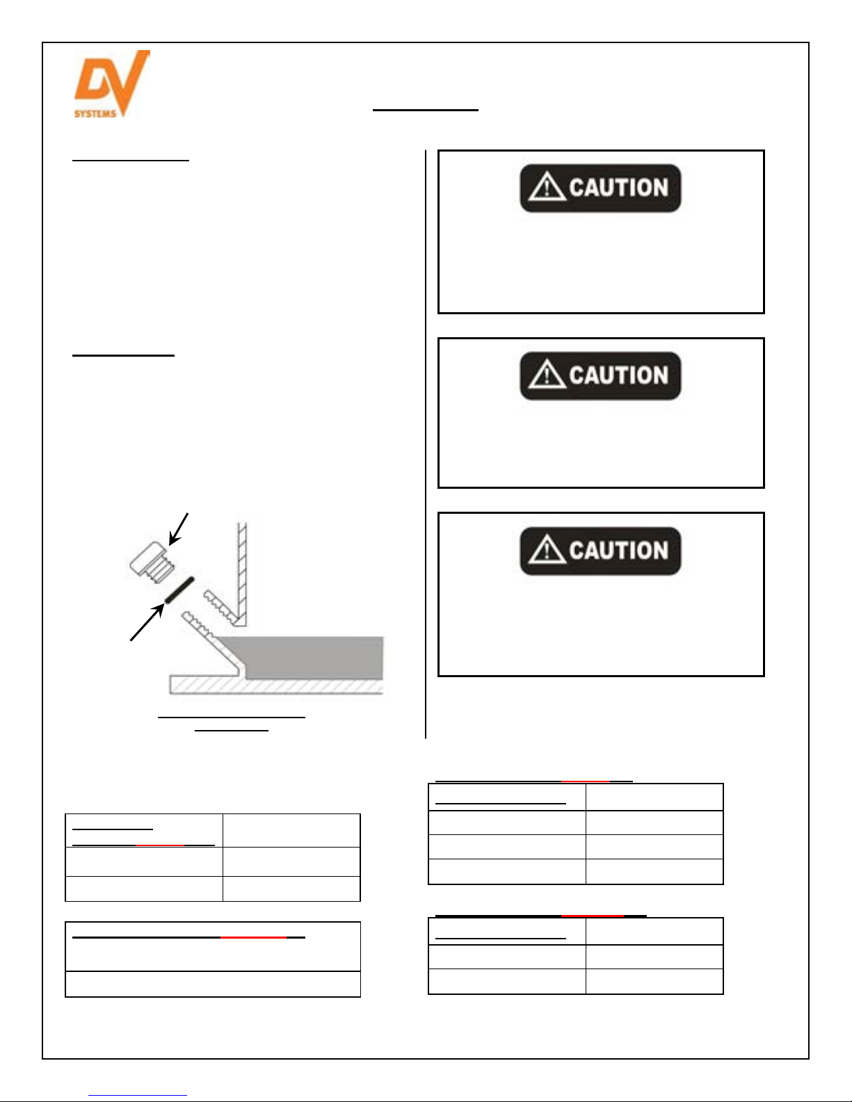
If anchoring the Unit, ensure that there is
approx. ¼” (0.75 cm) between the Nut and the
Compressor Foot (as shown below). Do not
bolt down tightly.
¼” (0.75 cm)
Gap
Floor
Isolator
Pad
Compressor
Fo
ot
Never clamp or bolt Air Receiver Feet to the
or or support structure. Doing so can
flo
greatly increase stress on the Tank, causing
it to weaken and/or fracture.
The Compressor must not be operated in a
confined area where the heat from the Unit
cannot readily escape.
If installed in a compressor room, ensure that the
room is adequately ventilated. (One Horsepower
produces approximately 2500 BTU/HR.)
Eg: 15 HP Unit x 2500 BTU/HP = 37,500 BTU/hour
The ambient temperature should be between
50°F and 104°F (10°C to 40°C).
Many common Compressor problems can be
attributed to the location or installation of the Unit.
Make sure the Unit is in a suitable location, and
installed correctly.
- 7 -
Lubrication
Initial Start
-
up.
Section Through Crankcase
DV Systems
Room (Am
bient)
DV Systems Premium
Synthetic
Oil
Each Compressor Unit built is extensively tested at the
factory before shipment. The Unit is shipped with the
original oil in it as used for testing purposes.
Check the oil level and for any oil leaks on a daily
basis. This must be done when the Unit is off. Top up
the Oil level on a monthly basis.
Use only DV Systems Premium Compressor Oil. Also,
do not mix the DV Systems oil with any other lubricant.
Oil Changes.
Drain the existing oil from the Unit. Running the Unit
prior to draining the oil will ensure that the oil will drain
relatively quickly.
Fill the Oil Reservoir to the bottom thread at the Oil
Filler Plug. Do not under or overfill. See drawing below.
O Ring
The following oils are available from your DV
Systems Distributor.
Premium Mineral Oils
20 Weight: ‘PR-20-4’ Up to 90°F (32°C)
30 Weight: ‘PR-31-4’ Above 90°F (32°C)
used in high heat or high duty applications or
when Beltguard Aftercoolers are used.
20 Weight: ‘OJ-2000’
Oil Filler Plug
At Oil Fill Port
Proper Oil Level
(to bottom thread of Oil Fill Port)
Temperature
is
HDI-03-W
Mar ‘15
Do not attempt to operate the Unit without
st checking whether there is oil in the
fir
Pump Crankcase. Add oil as required.
Serious damage may result from use,
however limited, without oil.
Use of improper oil may negatively affect
Compressor performance or shorten Unit life.
Resulting problems are not covered by the
DV Systems Warranty.
With limited Compressor use or installing in a
very humid environment, condensation
(water) may form in the Crankcase with the
oil. If this occurs, change the oil more often
than indicated on the Maintenance Schedule.
The following Maintenance Kits are available from
your DV Systems Distributor. The Kits include both
the Oil and Filters.
Kits c/w 20 Weight Mineral Oil
DV Systems Pumps Kit Part Number
123, 223 MK-223
247 MK-247
447 MK-447
Kits c/w 20 Weight Synthetic Oil
DV Systems Pumps Kit Part Number
247 MKS-247
447 MKS-447
- 8 -
 Loading...