

Page 1

16.june.2014
Page 2

2
Page 3

MARK VISION
A Word from Marco De Virgiliis
Thank you for choosing the DV AC 101 combo.
When I began to develop the concept of the Acoustic line in Italy several years ago, I had one objective in mind: to produce top quality acoustic amps that would
meet the needs of professional musicians everywhere.
I wanted my amps to be compact and lightweight and thanks to modern technology and the availability of high-quality components like digital power supplies,
neodymium speakers and so on, I was able to accomplish this.
Impressive musical clarity, tonal flexibility and satisfying bottom end are the reasons why many acoustic musicians choose the Markacoustic AC 101.
As for its predecessor, the new updated version DV AC 101 is designed specifically to not color the sound, but to faithfully reproduce the unique tonal qualities
of whatever instrument is played through it.
It includes 48V phantom power, feedback control and phase reverse, adding a new hi-performance compression driver, pre/post EQ switch for the XLR DI, FX send/
return, tuner out and a next generation of digital reverb and chorus that are sweet-sounding, warm and natural.
We hope you will enjoy your new acoustic amp, and we invite you to contact us any time with your comments and questions at [email protected]
.
Thanks again, and good music!
Marco De Virgiliis
3
Page 4

FRONT PANEL
1) INPUT CH1 Connect your acoustic instrument to this input using a standard ¼” shielded instrument cable.
2) CH1 GAIN
loop.
3) CH1 CLIP LED If playing through the amp causes the blue CLIP light to turn on at all, you should turn down the GAIN control to set the
optimal gain level for your instrument’s signal.
4) CH1 LOW This knob controls the amount of low frequencies in your sound, boosts or cuts the level of the frequencies around 40 Hz (± 16
dB).
5) CH1 MID This knob controls the level of mid frequencies, boosts or cuts the level of the frequencies around 600 Hz (± 16 dB).
6) CH1 HIGH This knob controls the level of high frequencies, boosts or cuts the level of the frequencies around 6 KHz (± 16 dB).
7) CH1 EFFECT MIX Controls the amount of effect in the channel 1.
8) EFFECTS) The DV AC101 features last generation of digital reverb and chorus effects, they are sweet-sounding, warm and natural. The
selected effect is common for CH1 and CH2, thanks to the separate Effect MIX (7-15) you can regulate the amount of effect for each channel.
9) PHASE SWITCH The Phase switch flips the polarity of your instrument signal from positive to negative, changing its relationship to the
sound coming from the amplifier. Use the Phase switch in conjunction with the Anti-Feedback control knob to eliminate acoustic feedback.
10) ANTIFEEDBACK The Antifeedback knob control is a variable frequency notch
filter designed to isolate and eliminate feedback. Turning the knob adjusts the center frequency of the filter, ranging from 20Hz (off) to 400Hz
at full clockwise.
11) INPUT CH2 This input accepts either a balanced XLR signal (for microphone or in case your intrument’s pickup supplies a balanced
output) or an unbalanced signal using a standard ¼” shielded instrument cable.
12) GAIN CH2 This controls how much signal is passed through the CH2 preamp stage of the unit, which includes equalization and the
effects loop. In case of condenser microphone or pickup system with phantom power, pull out the CH2 GAIN knob to engage 48V phantom
power on balanced XLR input.
13) CH2 CLIP LED If playing through the amp causes the blue CLIP light to turn on at all, you should turn down the GAIN control to set the
optimal gain level for your instrument’s signal.
This controls how much signal is passed through the CH1 preamp stage of the unit, which includes equalization and the effects
4
Page 5
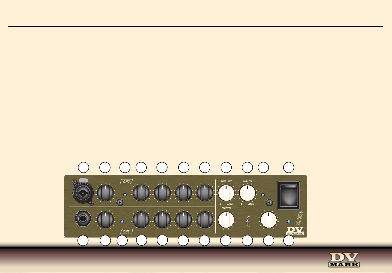
14) CH2 LOW This knob controls the amount of low frequencies in your sound, boosts or cuts the level of the frequencies around 60 Hz
(± 16 dB).
15) CH2 HIGH This knob controls the level of mid frequencies, boosts or cuts the level of the frequencies around 5 kHz (± 16 dB).
16) VPF The VPF (Variable Preshape Filter) knob boosts lows and highs, and cuts mids around 380 Hz. It’s very effective for strumming and
finger picking tecniques, and/or to cut mid and enhance low and high to the voice tone using a microphone connected to the XLR input of CH2.
17) CH2 EFFECT MIX Controls the amount of effect in the channel 2.
18) LINE OUT This knob controls the level of the signal from the XLR LINE OUT (29) to the mixing console in live or studio applications.
19) MASTER This control is the master feed from the end of the two preamp channels to the power stage section.
20) MIX CLIP LED If the MIX CLIP light to turn on at all, you’d turn down the EFFECT MIX level control to set the optimal effect level avoiding
its clip
21) MAIN ON/OFF SWITCH This switch delivers AC power to the amp. Make sure the unit is grounded; all three terminals of the AC power
plug must be connected to avoid any injury to the user or damage to the unit.
DV Mark amps and combos are manufactured to be used in the country where they have been sold, and are factory preset to that country’s
voltage. So make sure you’re sending the correct voltage to your amp before you connect it to AC power
22) ON LED A blue indicator LED is illuminated whenever the main on/off switch (19) is on and the amplifier is receiving power
INPUT
11
INPUT
1
12
GAIN
Min Max
GAIN
Min Max
2
PULL FOR
PHANTOM
13
14 16
LOW
-16 +16 -16 +16
LOW MID HIGH EFFECT MIX
CLIP
-16 +16 -16 +16 -16 +16
3 4
15
HIGH EFFECT MIX
5
VPF
Off Max Off Max
6 7
17 18 19 20
Off Max
21
OFF
CLIP MIXCLIP
PHASE
9
0°
180°
ANTIFEEDBACK
Off Max
10
ON
22
A
A
A
H
H
H
2
2
2
5
5
5
0
0
0
Chorus 1
Revb1
Revb 2
Revb 3
Revb 4
Chorus 2
8
5
Page 6

REAR PANEL
23) AC POWER SOCKET Make sure the unit is grounded; all three terminals of the AC power plug must be connected to avoid any injury
to the user or damage to the unit.
WARNING: The DV AC 101 is manufactured to be used in the country where they have been sold, and it is factory preset to that country’s
voltage. So make sure you’re sending the correct voltage to your amp before you connect it to AC power.
24-25) SPEAKER OUTS The DV AC 101 combo head features two speaker outputs, the high-quality SPEAKON COMBO output is connected
by default to the internal speaker, may you like to use a SPEAKON speaker cable to connect an 8ohm extension cabinet you can disconnect
the cable from internal speaker from the SPEAKON COMBO output and connect it to the JACK output.
The amp delivers 150W of power @ 4 ohm, or 250W @ 8 ohm (adding a 8ohm extension cabinet), speaker outputs are in parallel and minimum impedance load for the amp is 4 ohm.
26) TUNER OUT Is an unbalanced signal that can be sent to a tuner, allowing you to tune as you play without passing your signal through
pedals, which can degrade the quality of your signal. You can also use this output to send your signal on to another amp, or any kind of recording unit that doesn’t require a balanced signal.
27-28) SEND/RETURN If you use effect pedals or rack gear, you can route them through the SEND EFFECT (26) and RETURN EFFECT (25).
The effects loop is wired in parallel.
29) PRE/POST SWITCH It determines whether the signal that leaves the LINE OUT XLR (29) is affected by your amplifier’s EQ settings or
not. In most cases, you will find that sound engineers prefer to receive a pre-EQ signal. Note that the line out signal includes whatever effects
you’ve connected through the effects loop.
30) GROUND LIFT SWITCH Occasionally when you’re playing live and using the LINE OUT XLR (29), the soundman will detect a hum from
your amp’s signal. This is almost always due to a grounding problem related to your power source; you will likely eliminate this hum simply
by flipping the GROUND LIFT switch.
6
Page 7
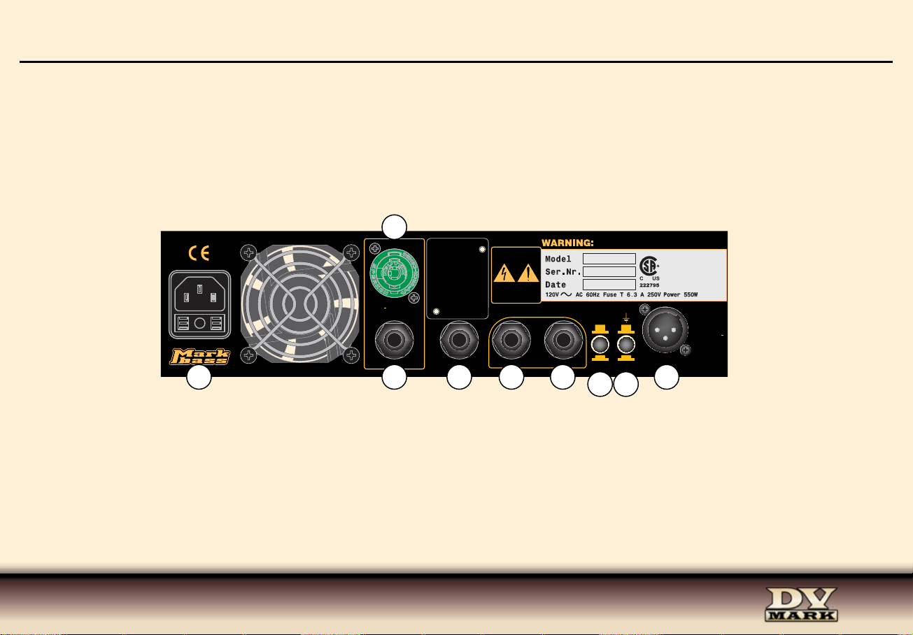
31) LINE OUT The balanced XLR output allows you to connect your amplifier directly to a mixing console (either in live situations or in a
A
H
2
5
0
A
H
2
5
0
A
H
2
5
0
INPUT
INPUT
LOW MID HIGH EFFECT MIX
Min Max
GAIN
Min Max
GAIN
PULL FOR
PHANTOM
-16 +16 -16 +16 -16 +16
ANTIFEEDBACK
LOW
CLIP
CLIP MIXCLIP
HIGH EFFECT MIX
-16 +16 -16 +16
Off Max Off Max
Off Max
Off Max
VPF
0°
PHASE
180°
Chorus 1
Revb 2
Revb 3
Revb 4
Chorus 2
Revb1
ON
OFF
15
1
2
3 4
5
8
9
6 7
10
11
12
13
14 16
17 18 19 20
21
22
recording studio) without the need of a DI box. Simply connect a standard XLR cable from this output to the soundboard/mixing console, or
a snake connected to the board/console.
23
25
SPEAKER OUT
1 + = SIGNAL
1 = GND
CLASS 2 WIRING
24
TUNER OUT RETURN EFFECT SEND EFFECT
CAUTION:
RISK OF ELECTRIC
SHOCK DO NOT OPEN.
AVIS:
RISQUE DE CHOC
ELECTRIQUE
NE PAS OUVRIR.
27
TO REDUCE THE RISK OF FIRE OR ELECTRIC SHOCK
DO NOT EXPOSE THIS PRODUCT TO RAIN OR MOISTURE.
PRE EQ
GND LIFTPOST EQ
2826
29
30
CAUTION:
FOR CONTINUED PROTECTION
AGAINST RISK OF FIRE
REPLACE ONLY WITH SAME
TYPE AND RATING FUSE.
ATTENTION:
REMPLACER UNIQUEMENT PAR
UN FUSIBLE DE MEME TYPE.
LINE OUT
31
BALANCED:
PIN1: GROUND
PIN2: SIGNAL +
PIN3: SIGNAL
7
Page 8

TECHNICAL SPECS
INPUTS:CHANNEL 1 Imp. 500 Kohm / max Vpp: 10
CHANNEL 2 Imp. 500 Kohm / max Vpp: 10
BALANCED CH2 Imp. 500 Kohm / max Vpp: 20
RETURN Imp. 33 Kohm / Max 10Vpp
CONTROLS CH1:GAIN -45dB ÷ 28 dB
EFFECT MIX Internal Effect only
EQUALIZER LOW: Level ±16 dB (40 Hz)
MID: Level ±16 dB (600Hz)
HIGH: Level ±16 dB min (6 KHz)
CONTROLS CH2:GAIN -43dB ÷ 26 dB
PHANTOM 48VDC
EFFECT MIX Internal Effect only
EQUALIZER VPF: Center Freq. (380 Hz=
LOW: Level ±16 dB (60 Hz)
HIGH: Level ±16 dB min @ (5 KHz)
OTHER CONTROLS: PHASE 0°, 180°
ANTIFEEDBACK 20Hz (off), 400 Hz
OUTPUTS SEND unbalanced, Max Voltage 20Vpp (Pre Eq)
TUNER OUT unbalanced, Max Voltage 2Vpp
SEND MIX balanced, Max Output: 20 Vpp
POWER OUT 150W/8 ohm - 250W/4 ohm
SUPP LY 100/120V/230V/240V 50/60Hz
(Version set inside the equipment)
Effects Description 1) Chorus + Reverb
2) Hall – Reverb time Medium High
3) Hall – Reverb time Medium
4) Room – Reverb time Medium High
5) Room – Reverb time Medium
6) Chorus
SPEAKER 1x10"
TWEETER 1" HF compression driver
BASS PORT rear
IMPEDANCE 8 ohms
SENSITIVITY 101 dB SPL
SPEAKER POWER HANDLING 200W RMS (AES Standard)
AMP OUTPUT POWER (analog) 250W @ 4 ohm / 150W @ 8 ohm
FREQUENCY RESPONSE 45 Hz to 20 kHz
CROSSOVER FREQUENCY 3.5 kHz
8
Page 9
Input 1
GAIN
CHANNEL 1
TONE
ELECTRIC
GUITAR
EFFECTS
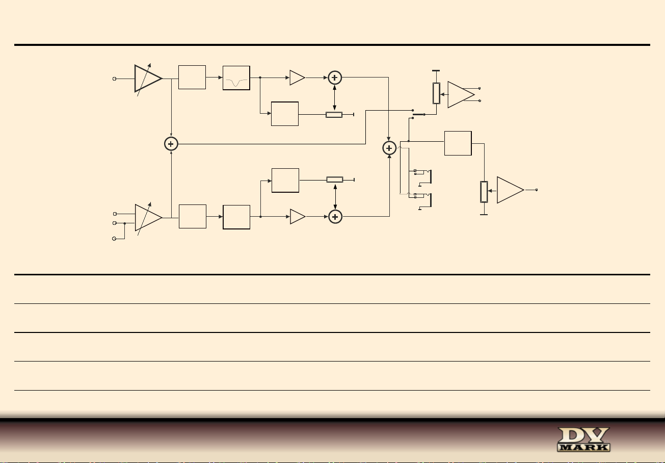
BLOCK DIAGRAM
Anti-
feedback
DirectBalanced
Pre
Direct
Post
Micro
Input 2
GAIN
TONE
CHANNEL 2
VPF
EFFECTS
Send
Return
Master
Power
Ampli
Power
Output
NOTES
Page 10

Product specications are subject to change without notice
www.markbass.it
TM
srl
Italy - 66020 San Giovanni Teatino CH - Via Po, 52
Tel: +39 0854407764 / 0854465705 - Fax: +39 0854407764 / 0854407399 - www.dvmark.it - [email protected]
 Loading...