

DVDO ScanHD+ Product Guide

1
Product Guide
English Version
How to install, set up, and use your new DVDO product
High Resolution
Video Scaling Engine
BY ANCHOR BAY TECHNOLOGIES

TABLE OF CONTENTS
Table of Contents 1
Introduction 2
Installation and Set-Up 3
System Requirements and Compatibility 3
Video Inputs
Digital Audio Inputs
iScan Rear View Connections 4
Signal Flow Diagram 4
Typical System Configuration 5
Output Signal Connections 6
Power Supply Input 6
Display Input Connectors 6
HD15 (VGA-type) Connector
Component (YPbPr ) Input with RCA Jacks
DVI Digital Video Input
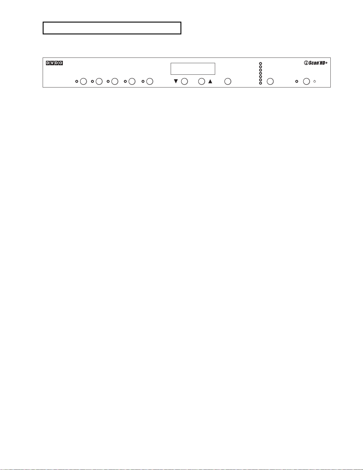
Displays and Controls 7
Initial Set-Up 7
Analog Component Output (YPbPr)
Analog RGB Output
DVI Output
Power/Standby Control 8
▲, ▼, and Enter/Exit Controls 8
Output Setup 8
Formats 9
Input Aspect Ratio Control 10
Picture Control 11
Saved Settings for Individual Inputs 11
Audio Operation 11
From the Front Panel
From the On-Screen Display (OSD)
Digital Audio Outputs
Input Adjust Control 12
Configuration Control 13
Customizing the Output Video Timing
for your Display 14
Automation Controls 14
Remote Control Operation 15
On-Screen Display (OSD) 15
Output Setup 15
Configuration 15
Picture Control 15
Input Adjust 15
Menu 15
Zoom 15
Pan 15
Aspect Ratio Buttons 15
Input Select Buttons 16
Power Button 16
Info 16
Curtain 16
Test Patterns 16
Technical Specifications 18
Safety Information 19
Warranty 20
Acknowledgements 20
INTRODUCTION
Thank you for purchasing the iScan HD+ High Resolution Video
Scaling Engine, featuring video-processing technology as created
by the Anchor Bay Technologies team. This product delivers a
level of video quality among the very highest available today.
We are especially pleased to bring you ABT’s new High Definition
Precision Video Scaling™ technology. This technology enables
precision upconversion of Standard and High Definition (480i,
480p, 576i, 576p, 720p or 1080i)) video sources and content to
the native or optimum resolution of your display, delivering
best-in-class front-of-screen performance. Available output resolutions span from 480p all the way to 1080p, including the
standard HDTV resolutions of 720p and 1080i. In addition to our
own video scaling technology, new to the DVDO product line, the
iScan HD also offers a host of other innovative features.
Among these are:
䊳
flexible Digital Audio switching
䊳
precision audio/video time-delay synchronization
䊳
improved timebase correction
䊳
fully programmable framerate conversion
䊳
input and output aspect ratio controls
䊳
flexible zoom and pan controls
䊳
SDI input capability
(with the DVDO SDI Video Input Module)
The
Technical Specifications section at the end of this
Product Guide summarizes the key features and performance
of the iScan HD
+.
This Product Guide will help you set up your new iScan HD
+,
and will also give you information on how to match it to your
display, as well as how to connect it to and use it with the
rest of the components in your system.
Should you have any questions during the setup or operation
of this DVDO product, you should first contact your Authorized
DVDO Reseller for assistance. You can also contact Anchor Bay
Technologies directly for assistance:
Toll-Free (in the USA) 1.866.423.DVDO
Email Help@DVDO.com
Website www.DVDO.com
The carton of your iScan HD
+ should contain the following:
䊳
iScan HD+ High Resolution Video Scaling Engine
䊳
Universal 6V@5A AC to DC power converter
䊳
US power cord (international customers - please
consult your local Authorized DVDO Reseller)
䊳
Remote control
䊳
iScan HD+ Product Guide
The iScan HD
+ uses a 15-pin HD15 VGA-type connector and a
DVI connector to provide video output signals. You will need to
purchase an output cable to connect one of these outputs to
your projector, HD-compatible TV, Plasma display panel, or
other display device. Different displays have different input
connectors, so please check your display specifications to ensure
compatibility. Even though the HD15 connector is commonly
used on personal computers for RGB video, the iScan HD
+ is
capable of outputting either RGB or YPbPr (Component) video
formats from this connector. This is explained in detail in the
Output Setup section of this Product Guide.
Both input and output cables can be supplied by your
Authorized DVDO Reseller. To find your nearest Authorized DVDO
Reseller, go to
www.dvdo.com/res/index.html
You can also find a wide selection of cables on our website at
www.dv do.com/pro/pro_acc.html
2
High Resolution Video Scaling Engine by Anchor Bay Technologies
Input
Aspect
Input
Select
Ratio
Picture
Control
Input
Adjust
Configuration
Analog
/ Digital
Format/Resolution
Enter/Exit
Adjust
Aspect Ratio
Colorspace
Display Profile
Output
Sync Type
Framelock
Setup
On/Remote
Standby
Power

System Requirements and Compatibility
The iScan HD+ is designed to drive displays that can accept
an ATSC Digital Television or VESA-standard PC video signal in
analog RGB or YPbPr (Component) video format, or digital
DVI format. Such displays include:
䊳
Projectors – DLP, LCD, CRT, D-ILA
䊳
HDTVs
䊳
Progressive scan and multimedia TVs
䊳
Plasma TVs
䊳
Computer monitors
If you are not sure if your display is compatible with the iScan
HD
+, please contact your local Authorized DVDO Reseller. Anchor
Bay Technologies also maintains display compatibility information
on the DVDO website at
www.dvdo.com/faq/faq_compat.html
Input Signal Connections
Video Inputs
The iScan HD+ has nine (9) video inputs. The inputs and the
formats they support are:
䊳
Video 1 (NTSC, PAL, and SECAM)
䊳
Video 2 (NTSC, PAL, and SECAM)
䊳
S-Video 1 (NTSC, PAL, and SECAM)
䊳
S-Video 2 (NTSC, PAL, and SECAM)
䊳
Component/RGBS 1 (NTSC, PAL, SECAM,
480p, 576p, 720p, 1080i)
䊳
Component/RGBS 2 (NTSC, PAL, SECAM,
480p, 576p, 720p, 1080i)
䊳
DVI/HDCP (480p, 576p, 720p, 1080i)
䊳
Analog Passthru (for use with sources for which no video
processing is desired, such as native HDTV or PC formats)
䊳
SDI (NTSC, PAL and SECAM – SMPTE 259M-C compliant)
High Definition signal formats (720p, 1080i) on the Component
inputs are automatically passed through to the output.
Video 1 and Video 2 inputs are also referred to as Composite
video inputs. In general, Composite video delivers the lowest
final image quality while Component video delivers the best
image quality. There is a large improvement in image quality
between Composite and S-Video, but the difference between
S-Video and Component video is less noticeable.
If you have a DVD player, satellite receiver or digital cable box
with DVI/HDMI output, it is recommended that you connect the
output to the iScan HD
+’s DVI input. The iScan HD+ will process
both Standard and High Definition sources on it’s DVI input
including 480p,576p,720p and 1080i. In addition, the iScan
HD
+ will also process HDCP protected content on its DVI input.
However, the iScan HD
+ will only output HDCP protected con-
tent on its DVI output with HDCP enabled. The iScan HD
+ will
not output HDCP protected signal on its analog output.
For sources with analog outputs, it is recommended that you use
the Component video inputs to connect to your iScan HD
+. VCRs
generally have the lowest image quality, and therefore will not
be as affected by the lower quality of the composite video signal
connection. An exception is S-VHS VCRs, which feature an
S-Video output of higher quality than conventional VHS VCRs.
The Analog Passthru input is used for analog video sources
that do not require processing, such as HDTV satellite broadcasts, video sources that are already in progressive format
or HD formats, or personal computer video output. This input
allows you to pass these signals through the iScan HD
+ without
any video processing.
Digital Audio Inputs
There are a total of four (4) Digital Audio inputs:
䊳
Digital Audio 1 (coaxial)
䊳
Digital Audio 2 (coaxial)
䊳
Digital Audio 3 (optical)
䊳
Digital Audio 4 (optical)
The iScan HD
+ accepts Digital Audio sourced from DVD players,
DBS receivers, digital cable set-top boxes, or other digital audio
devices. There are four (4) inputs; two each of Coaxial and
Optical transmission interface types. These inputs are compatible
with most consumer Digital Audio formats, including CD-Audio
(44.1kHz/16 bit linear pulsecode modulation), Dolby Digital, or
DTS. Generally, the Digital Audio inputs are compatible with any
format with a sampling frequency between 44 kHz and 96 kHz,
and with a data word structure between 16 and 24 bits in length.
3
INSTALLATION AND SET-UP
4
Installation and Set-Up
(continued)
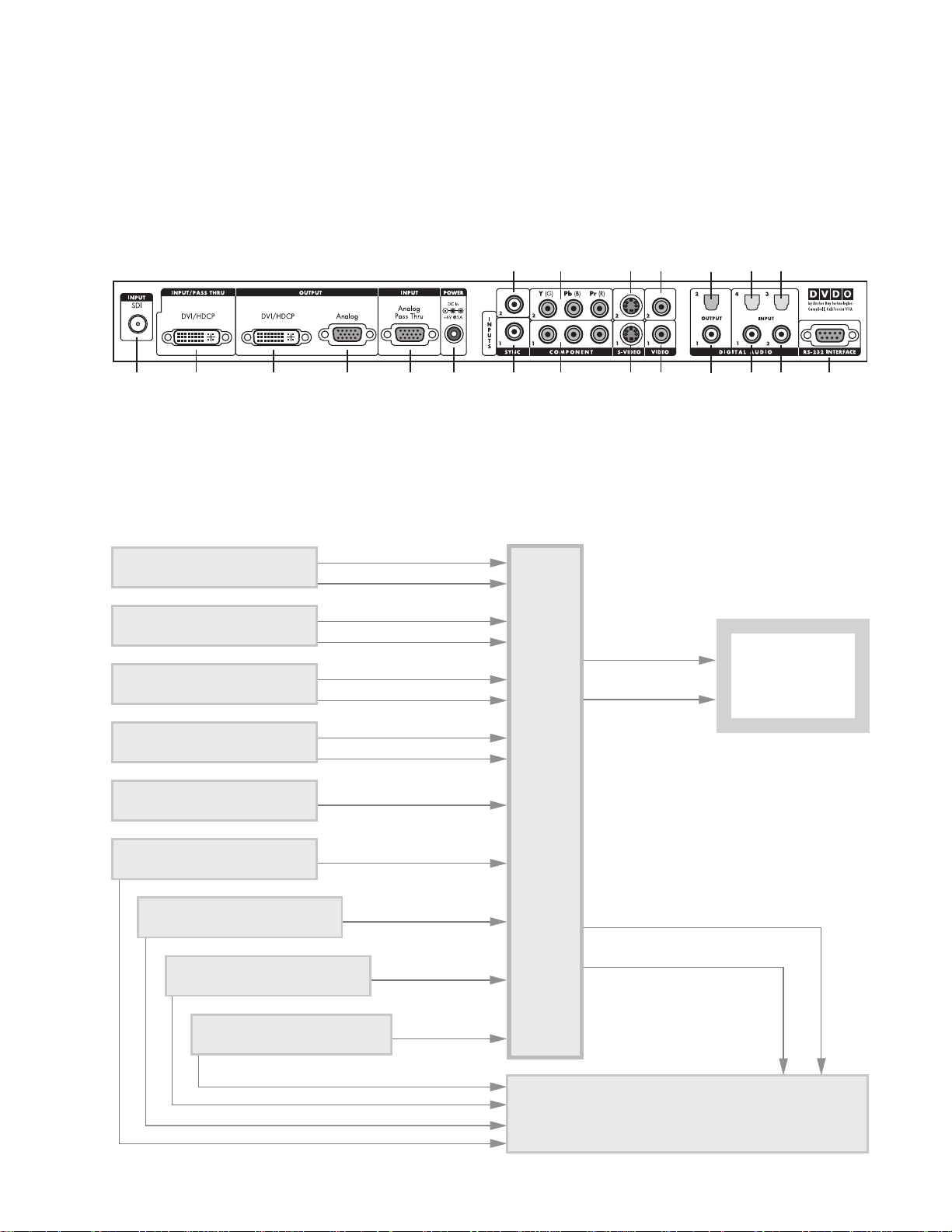
Signal Flow Diagram
The following diagram shows a typical way to use the iScan HD+
in a system. This figure depicts a system where the iScan HD+ is
used as the primary video switcher or “hub”. The iScan HD
+ is
usually placed between the display device and any video sources
and acts as the source switch for the display.
*
Component 2
(YPbPr or RGB)
Component 1
(YPbPr or RGB)
Power
Composite
Video 2
Composite
Video 1
Digital
Audio Out
2 (optical)
Digital
Audio Out
1 (coaxial)
Digital Audio
Inputs 4, 3
(optical)
Digital Audio
Inputs 1, 2
(coaxial)
Serial Port
S-Video 2
S-Video 1
Sync 2
Sync 1Analog
Output
Analog
Passthru
DVI OutputDVI InputSDI Input*
iScan Rear View Connections
The following figure shows the input and output connector com-
plement on the rear panel of the iScan HD
+. There are a total of
nine (9) Video inputs, two Video outputs, four (4) Digital Audio
inputs, and two Digital Audio outputs. Also shown are the DC
Power input and the RS-232 Serial Port.
DVD Player or other SDI* video
source with Digital Audio output
Digital Audio 3 (Optical)
SDI*
* SDI Video Input Module required
DVD Player or other Component video
source with Digital Audio output
DVD Player or other Component video
source with Digital Audio output
DBS Receiver, Game Console or other
S-Video source with Digital Audio output
Component Video 1 (YPbPr)
Digital Audio 1 (Coaxial)
Component Video 2 (YPbPr)
Digital Audio 4 (Optical)
S-Video 1
Digital Audio 2 (Coaxial)
iScan HD+
Analog video output
or
DVI-D digital video output
Projector, HD-Ready TV,
Plasma display panel,
computer monitor,
or other SD/HD capable
display device
Video
Analog
Audio
Inputs
Processor/
Scaler
Digital Audio Out 2 (Optical)
Digital Audio Out 1 (Coaxial)
AV Preamplifier/Processor or AV Receiver
Digital Audio Inputs
DVD Player or other
S-Video source
VCR or other
Composite video source
Laserdisc Player or other
Composite video source
HD-DBS Receiver, PC, or other
High Definition video source
HD-DBS Receiver, PC, or other
High Definition video source
Video 1 (Composite)
Video 2 (Composite)
S-Video 2
Analog Pass-Thru
DVI
Analog Audio (L/R)
5
Installation and Set-Up
(continued)
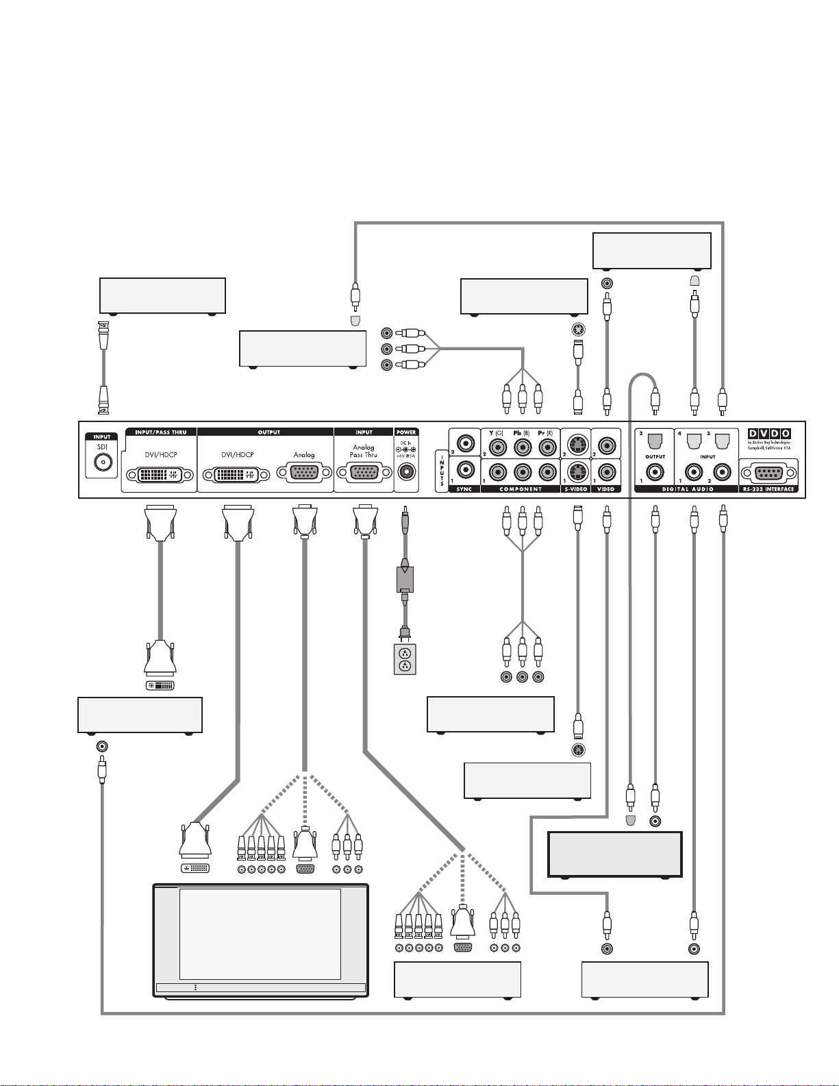
Typical System Configuration
The iScan HD+ is usually placed between the display device and
any video sources and acts as the source switch for the display.
Shown in this connection diagram are nine audio/video
sources, four of which have digital audio outputs along
with analog video outputs.
DVI-D
DVI-D
DVI-D
Progressively Scanned TV or Projector
Universal
Power Adaptor
AC Mains
(100-240 VAC
50/60 Hz)
Component
Video Cable
S-Video Cable
Composite Video Cable
S-Video Cable
Composite Video Cable
Digital Audio Cable (Optical)
Digital Audio Cable (Coaxial)
Digital Audio Cable (Coaxial)
Digital Audio Cable (Coaxial)
Component Video Source
(480i, 480p, 720p, or 1080i)
YPbPr
VCR or Other
S-Video Source
Component Video Source
(480i, 480p, 720p, or 1080i)
Set-Top Box or Other
DVI source
HD Satellite TV Tuner, PC, or
Progressive-Scan DVD Player
5x BNC
3x RCA
or
or
Video Game or Other
Composite Video Source
Set-Top Box or Other
S-Video Source
Video Game or Other
Composite Video Source
DVI-D
Audio/Video Preamplifier/
Processor or AV Receiver
Component
Video Cable
Digital Audio Cable (Optical)
Digital Audio Cable (Optical)
YPbPr
Digital Audio Cable (Optical)
HD Video
DVI-D or DVI-I Interface Cable
DVI-D or DVI-I
Interface Cable
HD Video
5x BNC
3x RCA
or
or
HD15 HD15
HD15
HD15
Rear View of
iScan HD+
*
BNC Cable
DVD Player or Other
SDI* source
* SDI Video Input Module required
Digital Audio Cable (Coaxial)
Output Signal Connections
There are two output connectors on the back of the iScan HD+:
1) 15-pin HD15 Analog Output (VGA-type)
2) DVI Digital Video Output (with HDCP)
Use the 15-pin HD15 ouput of the iScan HD
+ to interface
to displays with a Component or VGA input. Use the DVI output
of the iScan HD
+ to interface to displays equipped with the
DVI interface.
Power Supply Input
The iScan HD+ comes with a 6V@5A AC to DC converter power
supply, which accepts 100-240 VAC at 50/60Hz. Connect this to
the ‘DC In’ port on the back of the iScan HD
+. IMPORTANT: Use
only the power supply that came with your iScan HD+, or a
replacement procured directly from Anchor Bay Technologies.
Display Input Connectors
There are a number of different connectors used on displays,
such as RCA, 15-pin HD15 (VGA-type), BNC and DVI connectors.
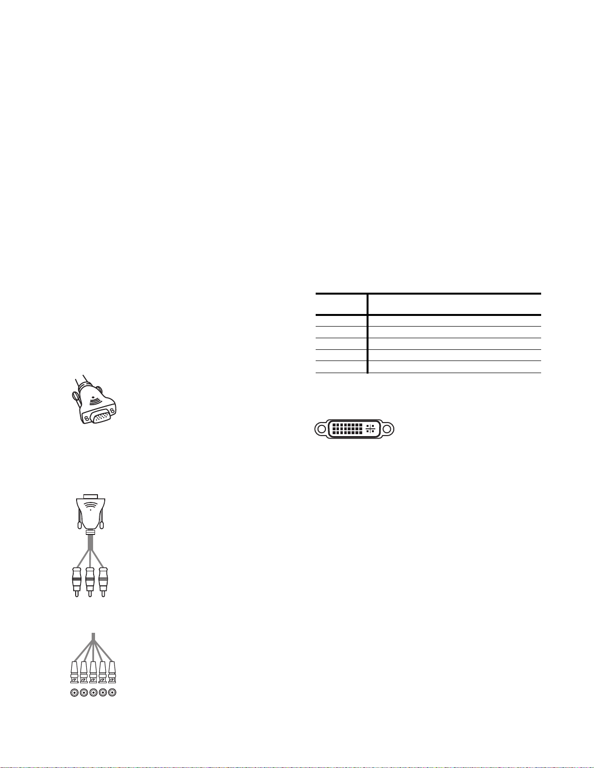
HD15 (VGA-type) Connector
The VGA cable/connector is commonly used
in PC applications and should be readily
available in any computer or electronics store.
Select a well-shielded high-quality cable to
reduce reflections and other degrading effects on
the video signal. Most multimedia TVs/displays with progressive
scan capability will have an input of this type and should
accept both YUV and RGB color formats.
Component (YPbPr ) Input with RCA Jacks
Most displays with Component video inputs
will have three RCA jacks for YPbPr video signal
connections. Use the DVDO Precision HD15 to
3-RCA Component Video Cable (ABT part number
11-2001-01) to connect to these displays.
You can find it on our website at
www.dvdo.com/pro/pro_acc.html
Connect the three signal lines to the correspond-
ing color RCA jacks on your display.
BNC Connectors
Many displays such as home theater projectors
have five BNC connectors instead of an HD15
connector. For these displays, use an adapter
cable to convert from VGA to the BNC connectors
used on the display. These adapter cables are
readily available through most home theater
retailers and have a VGA connector on one end and BNC
connectors on the other. The BNC end of the cable will usually
have five connectors (labeled R, G, B, Hsync, and Vsync),
although not all will necessarily be needed for every display.
Please refer to your display’s specifications to determine which
input signals it requires. If your display device accepts
Component video (YPbPr), then you will not need the H and V
lines since these sync signals are actually part of the information in the ‘Y’ signal. If your display device requires RGBS, then
this is Composite Sync, which is sent on the H (white/gray)
line. Displays that require RGBHV will require all 5 BNC connectors. Hsync is sent on the white/gray wire, and Vsync is sent on
the yellow/black wire.
Below is a table showing the signal mappings for each wire of
the BNC cable.
DVI Digital Video Input
The DVI digital video connector is
used on many newer digital TVs and
is similar in functionality to the
analog VGA connector except that the video signal is transmitted digitally from the iScan HD
+ to the display device. This
provides the highest possible quality video image from the iScan
HD
+ to the display. Many displays also support the High-band-
width Digital Content Protection (HDCP) specification across
the DVI interface. Displays with a DVI/HDCP input will show
protected content from the iScan HD
+ DVI output.
Once you have the iScan HD
+ connected to your home theater
system, there are several configuration parameters that you may
adjust to output the proper signal format for your display device
and optimize the image to your personal preferences.
6
Installation and Set-Up
(continued)
Input Type
Wire Color RGB/HV RGBS YPbPr YUV/HS
(Component)
Red R (Red) R (Red) Pr U
Green G (Green) G (Green) Y Y
Blue B (Blue) B (Blue) Pb V
White or Gray H sync Composite sync No Connect H sync
Yellow or Black V sync No Connect No Connect V sync
 Loading...