

DVDO iScan VP50pro Owner's Manual
H I G H - D E F I N I T I O N V I D E O P R O C E S S O R & H U B
O W N E R ’ S M A N U A L

T A B L E O F C O N T E N T S
S E C T I O N 1 – G E T T I N G S T A RT E D 2
Introduction 2
Unpacking and Inspection 2
Display Compatibility Requirements 3
Document Conventions 3
Menu Navigation 3
Remote Control Battery Installation 4
Remote Control Overview 4
Info Screen 5
Installation Guidelines 6
S E C T I O N 2 – B A S I C O P E R A T I O N 7
Front Panel Overview 7
Rear Panel Overview 7
Video Inputs 8
Video Outputs 8
Audio Inputs 8
Audio Outputs 9
12V Trigger Outputs 9
RS232 Serial Connection 9
Power Supply Input 9
S E C T I O N 3 – S E T U P 10
Initial Set-Up 10
STEP 1 - Power Up 10
STEP 2 - Connect the iScan VP50
STEP 3 - Selecting the Optimal Output Resolution on the
iScan VP50
STEP 4 - Connecting the Sources to the iScan VP50
STEP 5 - Conguring the Sources to Get Maximum Performance 12
STEP 6 - Deinterlacing Mode and PReP™ 14
STEP 7 - Assigning Audio Inputs to Video Inputs 15
STEP 8 - Display Optimization – Using Display Adjustments 15
STEP 9 - Source Optimization – iScan Adjustments 16
PRO
to the Display 10
PRO
for the Connected Display(s) 10
PRO
12
1

P RO
Advanced Setups 17
Conguring the iScan VP50
PRO
for projectors with
anamorphic lenses
Conguring the iScan VP50
PRO
to output 24/48/72Hz
and 25/50/75Hz
S E C T I O N 4 – M E N U O P T I O N S 18
Input Select 18
Input Aspect Ratio Control 18
Frame Aspect Ratio 19
Active Aspect Ratio 19
Panorama 19
Zoom 20
Pan 20
Borders 20
Presets 21
Input Adjust Control 22
Mosquito Noise Reduction 22
Deinterlacing 22
PReP™, Progressive ReProcessing 23
Pass Through 23
Overscan 23
Image Shift 23
Color Space 23
Input Level 24
VCR Mode 24
HDMI Conguration 24
Auto Input Priority Selection 24
Audio Input 25
AV Lip Sync™ 25
Picture Controls 25
Fine Detail 25
Edge Enhancement 25
Brightness 25
Contrast 25
Saturation 25
Hue 26
Y/C Delay 26
Chroma Filter (Auto CUE-C™) 26

T A B L E O F C O N T E N T Si S C A N V P 5 0
Conguration 26
Test Patterns 26
Auto Standby 26
LED Brightness 26
User Mode 27
Serial Port Rate 27
Factory Default 27
Software Update 27
12V Trigger Levels 27
Information 27
Output Setup 27
Analog/Digital 28
Output Format 28
Output Aspect Ratio Control 28
Sync Type 30
Color Space 30
Output Level 30
Framerate Conversion 30
Border Level 32
Picture Controls 32
HDCP Mode 32
12V Triggers 32
Display Proles 33
S E C T I O N 5 – C O M P LE T E M E NU T R E E 34

S E C T I O N 1 – G E T T I N G ST A RT E D
Introduction
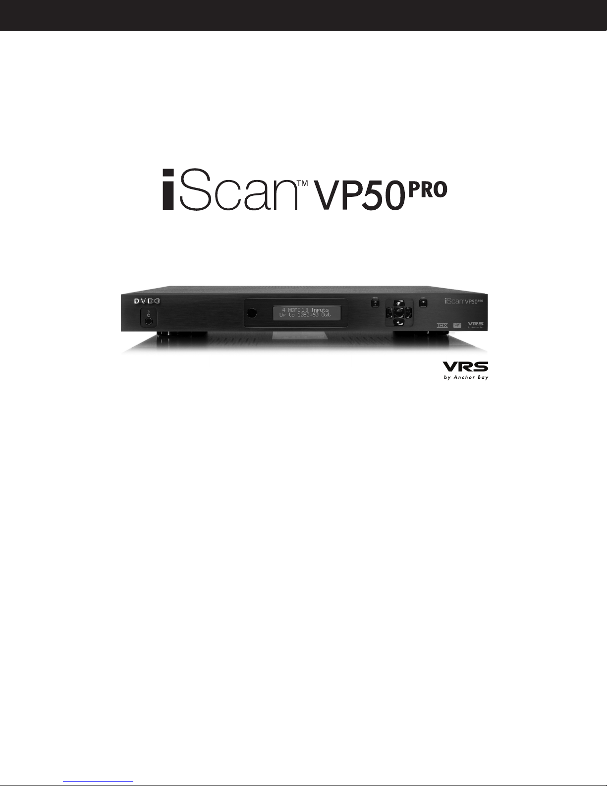
Thank you for purchasing the iScan VP50
Series) component available with:
• Mosquito Noise Reduction
• Fine Detail Enhancement™
• Edge Enhancement
PRO
video processor, the rst VRS (Video Reference
VRS Technologies included in the iScan VP50
PRO
are:
• 10-bit Precision Deinterlacing™ of 480i/576i/1080i
• 10-bit Precision Video Scaling™ up to 1080p
• PReP™, Progressive ReProcessing of 480p/576/1080p
• Progressive Cadence Detection™ of 480p/576p/720p/1080p
• Rightrate™ High Performance Frame Rate Conversion
In addition to our own award winning video processing technologies, the iScan VP50
PRO
also
offers a host of other innovative features, including:
• 4 HDMI 1.3 (High Denition Multimedia Interface) Inputs and 1 HDMI 1.3 Output
• THX Video Certication
• ISF ccc Certication
• 2 Programmable 12 V Triggers to control other devices
This Owner’s Manual can help you set up your iScan VP50
PRO
, and give you the information
required to understand the total. It can also show you how to properly connect it and use it with
the other components in your system.
Unpacking and Inspection
Please verify that your iScan VP50
• iScan VP50
PRO
Video Processor
• Universal 6V@7A AC-to-DC Power Converter
• US IEC Power Cord (International Customers, consult your local authorized
DVDO reseller)
• Remote Control
• iScan VP50
• iScan VP50
PRO
Owner’s Manual
PRO
Quick Start Guide
• Serial Cable for Software Updates and Automation (1:1)
• VRS Optimization & Evaluation DVD
• DVDO Software CD
• Rack Mount Kit
• RCA-to-BNC Adapters (5)
PRO
carton contains the following items:
If you are missing any items, please contact your dealer or the DVDO Support Team.
The iScan VP50
video output signals. Five RCA-to-BNC adapters are included to facilitate using the analog input or
output with a cable terminated with RCA connections. Additional cables or adapters are required
to connect the iScan to your source(s) and display(s). Different displays have different input
connectors, so check your display specications to ensure compatibility.
PRO
uses BNC-style analog connectors and an HDMI digital connector to provide
2
4
Both input and output cables can be supplied by your Authorized DVDO Reseller. To nd your
nearest Authorized DVDO Reseller, go to www.anchorbaytech.com. There are also a wide selection
of cables and adapters available directly from Anchor Bay.
Display Compatibility Requirements
DVDO iScan video processing products are compatible with a wide range of displays. These include
digital TVs, projectors, and at panel displays, as well as other emerging technologies that can
support 480p or higher resolution video signals. To determine if your display is compatible with the
DVDO iScan VP50
may only have analog High Denition inputs or it is probably limited to receiving a standard NTSC, PAL
or SECAM interlaced signal and will not function correctly with VP50
include Component Video (YPbPr) and RGBHV using HD15 and/or 5 BNC terminated coaxial cables.
Component inputs that are not capable of accepting a 480p signal, at a minimum, are usually labeled
‘480i’ (NTSC) or ‘576i’ (PAL/SECAM).
PRO
, look to see if it has an HDMI or DVI digital video input. If not, then your display
PRO
. High Denition Analog inputs
The following types of xed-pixel displays with digital video inputs should be compatible with the
iScan VP50
PRO
since a large majority of them can support higher resolution signals:
• Plasma displays
• LCD-based at panel and front & rear projection displays
• DLP-based front & rear projection displays
• LCoS-based front & rear projection displays (D-ILA™ & SXRD™ included)
Document Conventions and Menu Navigation
In this Owner’s Manual, an action that requires navigating the menu system of the iScan VP50
is referred to in the following abbreviated form:
Picture Control _ Brightness _5
For example, to adjust the ‘Brightness’ to a value of ‘5’, press Picture Control and then press q three
times, highlighting ‘Brightness’ in the on screen display (OSD) or if you are looking at the front panel
display (FPD) you will see ‘Picture Control’ on the top line and ‘Contrast’ on the bottom line. This is
abbreviated as ‘Picture Control / Contrast’. Next press u to adjust the setting and then press p until
the value is ‘5’. Finally press Exit.
PRO
Text that is in bold refers to a button on the remote control of front panel of the iScan.
Text that is in ‘quotes’ references an item that is in the On Screen Display.
Text that is in italics references other sections of this Owner’s Manual.
The t , u,q, and p symbols refer to the navigational keys on the remote control and the front panel
of the iScan.
3

Menu Navigation
The iScan VP50
• From the front panel controls
• From the iScan VP50
• From a programmed universal remote control
• Using the serial connection on the back panel
PRO
can be controlled the following ways:
PRO
remote control
The menu navigation controls on the remote control are duplicated on the front panel of the iScan VP50
PRO
To navigate the menu:
1. Press the Menu button.
2. Use the directional buttons
3. Press the
Enter or u button to select the parameter and the p and q buttons to change
(t ,p,q, u) to highlight the parameter you want to change.
the chosen parameter. Press the t button to stop adjusting a parameter and to return
to navigating the OSD.
4. Press the Exit button to exit out of the menu/OSD
Remote Control Battery Installation
The remote control uses two AAA batteries, which should be replaced as needed. Two AAA batteries
are included.
To install the remote control batteries:
1. Locate the battery compartment on the back of the remote control.
2. Remove the cover from the back. To do this, press the tab attached to the cover and pull the
cover with the guide on the back of the remote control.
3. Remove the old batteries (if applicable).
.
4. Insert two new AAA batteries in the compartment as shown on the inside of the battery
compartment. Make sure the batteries are correctly inserted, observing the proper polarity.
5. After installation, replace the cover and dispose of the old batteries (if applicable).
4
6
INPU T SELEC T
STANDBY
POWER
INPUT
ADJUST
CONFIG
PICTURE
CONTROL
OUTPUT
SETUP
MENU EXIT
16:94:3
AUTO
VIDEO 1S-VIDEO 1COMP 1HDMI 2
VIDEO 2S-VIDEO 2COMP 2HDMI 3
ENTE R
HDMI 4
BORDER CROP
INFO
CURTAIN
MEMO RIES
RGBHV
HDMI 1 SDI
ASPECT
ZOOM PAN
ON/OFF
DISPLAY
PROFILES
VIEWING
MODES
INPUT
ASPECT
RATIO
TEST PATTERN
ENTE R
Standby
Info
Curtain
Output Setup
Configuration
Picture Control
Input Adjust
Menu
Border
Zoom
Input Select
(HDMI 1, HDMI 2, HDMI 3, HDMI 4,
Component 1, Component 2,
RGBHV/Component,
S-Video 1, S-Video 2,
Video 1, Video 2, AUTO)
Aspect
Exit
Crop
Pan
Power
Input Aspect
Ratio
Viewing Modes
Display Profiles
4:3
16:9
Test Patterns
(Left, On/Off, Right)
5
26
17
*
32
4
20
21
21
6
5
5
28
26
25
22
4
4
20
18
20
18
21
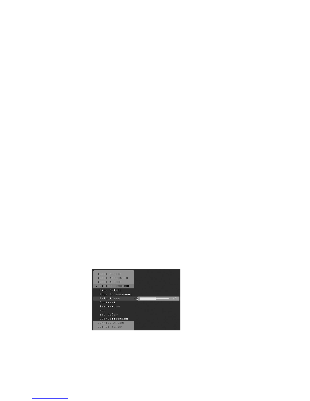
Remote Control Overview
For additional information about the functions of these buttons, turn to the pages given in
parentheses ( ).
An asterisk (*) indicates a feature that has not yet been implemented.
Power/Standby Buttons
The iScan VP50
iScan VP50
Info Button
This iScan VP50
contains important input and output information which can help with troubleshooting. The software
version which is loaded in the unit will also be displayed on this window and on the front panel display
PRO
PRO
on and the Standby button always put the unit into Standby mode.
of the iScan.
remote has a Power and a Standby button. The Power button always turns the
PRO
has an ‘Info’ screen which brings up a window on the connected display which
5

Curtain Button
The iScan VP50
PRO
remote has a Curtain button which allows you to close a ‘curtain’ over the image.
This feature is especially useful when an image is paused on a display susceptible to burn-in or a transition while switching inputs as part of a macro on a universal remote or automation system.
Discrete IR Codes and Serial Automation Protocol
Almost all commands that are available in the On Screen Display can be executed discretely using a
programmable IR remote control or automation system connected via an RS232 serial connection.
These codes are available at www.anchorbaytech.com
Non-Volatile Memory Settings
The iScan VP50
retains its contents when power is lost. There is one group of system settings and one group of user
settings.
PRO
stores a variety of user settings in non-volatile memory. Non-volatile memory
Installation Guidelines
Take special care with the iScan VP50
tion to the bulleted items that begin below and to other precautions that appear throughout this guide.
PRO
installation to ensure optimal performance. Pay particular atten-
Do . . .
• Install the iScan VP50
You can also install the iScan VP50
rack-mount kit available from authorized DVDO resellers or directly from DVDO.
• Select a dry, well-ventilated location.
• Use only the included external power supply.
• Avoid excessive humidity, sudden temperature changes or temperature extremes.
• Use only accessories recommended by the manufacturer to avoid re, shock or other hazards.
• Unplug your VP50
PRO
on a solid, at, level surface such as a table or shelf.
PRO
before cleaning. Use a damp cloth for cleaning.
PRO
in a standard 19” equipment rack using an optional
Don’t . . .
• Install the iScan VP50
four of its feet, unless it is installed in an equipment rack.
• Stack the iScan VP50
ampliers or other components that generate heat during use.
• Expose the iScan VP50
or excessive dust. Avoid installing the iScan VP50
producing appliances.
• Install the iScan VP50
other RF -emitting devices that might cause interference.
• Place the iScan VP50
This might prevent proper cooling.
PRO
on an unstable surface or one that is unable to support all
PRO
directly above heat-producing equipment such as power
PRO
to a high temperatures, humidity, steam, smoke, dampness,
PRO
near unshielded TV or FM antennas, cable TV decoders, and
PRO
on a thick rug or carpet or cover the iScan VP50
PRO
near radiators and other heat
PRO
with cloth.
• Attempt to service this unit. Instead, disconnect it and contact your Authorized DVDO
Reseller or contact Anchor Bay Technologies directly.
• Open or remove unit panels or make any adjustments not described in this manual.
Attempting to do so could expose you to dangerous electrical shock or other hazards.
It may also cause damage to your iScan VP50
• Obstruct the front panel IR receiver window shown in “Remote Control Overview”.
• Do not attempt to use the remote control out of line of sight with the IR receiver.
Doing so will cause improper operation.
PRO
.
6
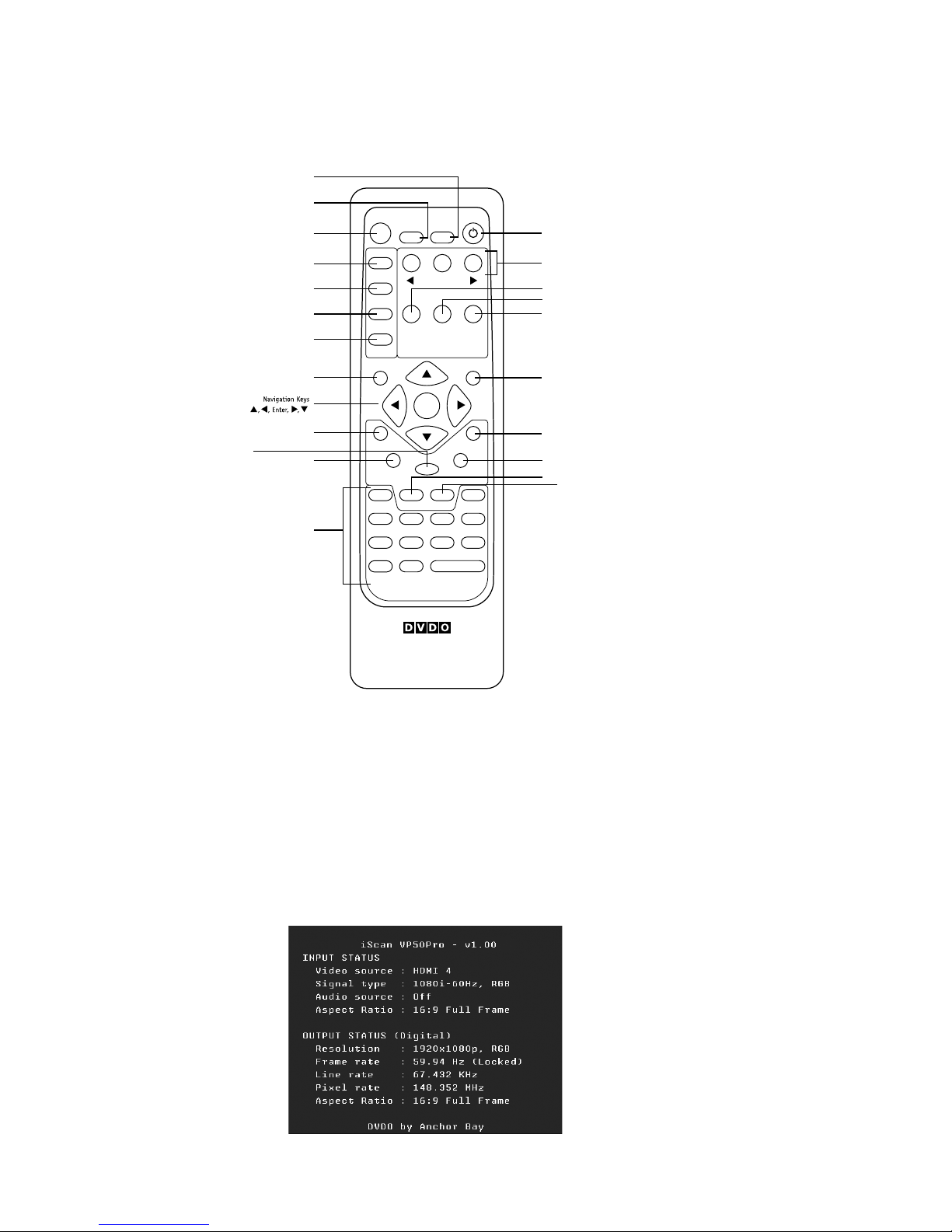
8
S E C T I O N 2 – B A S I C O P E R A T I O N
MENU
EXIT
Front Panel Display (FPD)
Navigation Keys
Up
On/Standby Left Down Right
Menu
Exit
IR WindowStatus LED Enter
MENU
EXIT
HD MI
1 2 3 4
INPUT
OUTPUT
1
324
SERIA L PORT
ANALOG AUD IO INPUT
Y (G) Pb (B) Pr (R) H V
DC In
Y (G) Pb (B) Pr (R)
1
212
121
2
L R
AN A LO G VI D EO
I
N
P
U
T
S
I
N
P
U
T
O
U
T
P
U
T
Front Panel Display (FPD)
Navigation Keys
Up
On/Standby Left Down Right
Menu
Exit
Power
Video 1
Video 2
Optical
Digital
Output
Coaxial
Digital
Output
Optical
Digital Input
1 & 2
Coaxial
Digital Input
3 & 4
Serial Port
S-Video 1
S-Video 2Component/RGBS 2
Component/RGBS 1
RGBHV/Component
Output
HDMI Inputs
1– 4
HDMI Output
Analog Audio
Input
DI G IT AL A UD I OS-VID EO VI DEOSYNCPOWER
HD-SDI Inputs (Optional)
1 & 2
RGBHV/Component
Input
IR WindowStatus LED Enter
CO M PO NE NT
12V Triggers
1 & 2
Front Panel Overview
Status LED – This displays the current state of the iScan VP50
PRO
Off = The unit is in standby mode
Red = No signal detected
Blue = The unit is processing the signal
Blinking Blue = There is a problem with HDCP authentication
Green = The unit detects an unsupported signal
Blinking Green = In Pass Through there is a problem with HDCP authentication
On/Standby Button – This toggles unit power between On and Standby.
IR Window – This is where all IR commands are received by the iScan. Do not obstruct this window.
Front Panel Display (FPD) – This is where all information from the on screen display (OSD) is
duplicated to assist in the setup of your iScan.
NOTE: When navigating the Menu, the Front Panel Display (FPD) always shows the current selec-
tion on the bottom line and the menu/submenu item on the top line. When you change a value of a
setting, the value is on the bottom line and the title of the parameter is on the top line.
Navigation Buttons – These buttons are available both on the front panel and on the remote control.
NOTE: Switching Inputs using the Navigation buttons – You can switch inputs on the front panel of
the iScan VP50
PRO
or using the remote using the navigation buttons. To do this, press the ▼ or ▲
without pressing the Menu button rst.
Back Panel Overview
7

Video Inputs
The iScan VP50
input.
PRO
has eleven (11) video inputs. Most popular formats are supported on each
Video Inputs
The iScan VP50
The formats, colorspace and bit-depth that the inputs support are as follows:
• Video 1 and Video 2
— Formats: NTSC, PAL, PAL-M and SECAM
• S-Video 1 and S-Video 2
— Formats: NTSC, PAL, PAL-M and SECAM
• Component/RGBS 1 and Component/RGBS 2
— Formats: 480i/p-60, 576i/p-50, 720p-50/60, 1080i-50/60
— Colorspace: YPbPr and RGBS
• RGBHV/Component
— Formats: 480p-60, 576p-50, 720p-50/60, 1080i-50/60, VGA/SVGA/XGA/SXGA-60
— Colorspace: RGBHV and YPbPr
• HDMI 1, HDMI 2, HDMI 3 and HDMI 4
— Formats 480i/p-60, 576i/p-50, 720p-50/60, 1080i-50/60, 1080p-24/25/30/50/60,
VGA-60, SVGA-60, XGA-60, SXGA-60
— Colorspace RGB/YCbCr 4:4:4/YCbCr 4:2:2
— Bit-Depth: 8/10 processed Up to 12-bit passthrough
PRO
has eleven (11) video inputs.
Video Outputs
The iScan VP50
iScan VP50
• YPbPr (Component)
• RGBHV
• RGsB
• RGBS
The HDMI digital video output can output the following signal types:
• RGB 4:4:4
• YCbCr 4:2:2
• YCbCr 4:4:4
To connect the iScan VP50
or an adapter.
PRO
has two video outputs, one analog and one digital. The analog output on the
PRO
can output the following signal types:
PRO
to a display that has a DVI input, use either an HDMI-to-DVI cable
Audio Inputs
There are nine (9) audio inputs on the iScan VP50
• Two (2) Optical Digital inputs
• Two (2) Coaxial Digital inputs
• One (1) Analog (L/R) input
• Four (4) HDMI 1.3 inputs
PRO
:
While the digital and analog audio inputs can be assigned to any one of the video inputs, the HDMI
audio inputs are tied directly to the HDMI video signal connected on the same input.
8

10
The iScan VP50
PRO
accepts digital audio sourced from DVD players, satellite receivers, digital set top
boxes, HD-DVD players, Blu-ray players, game consoles, and other video components with digital
audio. These inputs are compatible with most consumer digital audio formats, including CD-Audio
(44.1kHz/16 bit LPCM), Dolby Digital, and DTS. The coaxial digital audio inputs are compatible with
any format with a sampling frequency between 24kHz and 192kHz, and with a data word structure up
to 24 bits in length. The optical digital audio inputs are compatible with any format with a sampling
frequency between 24kHz and 96kHz and with a data word structure up to 24 bits in length.
The HDMI audio inputs are compatible with all of the HDMI 1.3 audio formats.
Audio Outputs
There are two discrete digital audio outputs, one coaxial and one optical. Both are active at the same
time, with the selected input audio stream.
The HDMI 1.3 output carries both audio and video.
12V Trigger Outputs
There are two 12-volt trigger ports that are designed to supply a combined total of 500mA.
RS232 Serial Connection
This connection is used as an interface to control the iScan VP50
to update the software in the iScan VP50
PRO
. The most current software version is available at www.
anchorbaytech.com.
PRO
with an automation system and
Power Supply Input
The iScan VP50
VAC at 50/60Hz.
PRO
comes with a 6V@7A AC-to-DC converter power supply, which accepts 100-240
9

S E C T I O N 3 – S E T U P
STEP 1 - Power Up
1. Attach the removable power cord to the external power supply.
2. Plug the removable power cord into a wall outlet or power conditioner, if applicable.
3. Plug the small connector attached to the cable that comes out of the power supply into
the iScan. The iScan should power on and display ‘DVDO iScan VP50
on the Front Panel Display (FPD). If this does not happen, check all connections and
verify that the power outlet does supply power with another device.
PRO
/ by Anchor Bay’
IMPORTANT: Use only the power supply that came with your iScan VP50
replacement procured directly from Anchor Bay
PRO
, or a
STEP 2 - Connect the iScan to the Display
Displays with a DVI or HDMI Input
Based on the factory default settings, just connecting an iScan to a display with an HDMI or
DVI input should complete this step as the default output is for the HDMI output to be active with
a RGB 4:4:4 signal which is the standard signal for a DVI/HDMI connection. Press the Menu
button once to conrm that you can see the On Screen Display (OSD).
Displays without a DVI or HDMI input:
Follow Steps 1-4 for a Component Input and Steps 1-8 for an RGBHV Input
Press the Menu button on the front panel of the iScan once. You should see ‘MAIN MENU / INPUT
SELECT’ on the FPD.
1. Press the Output Setup button once. You should see ‘MAIN MENU / OUTPUT SETUP’
on the FPD.
2. Press the
3. Press the
button once so that ‘Analog/Digital / BNC (Analog)’ is displayed on the FPD.
Press the Enter button.
4. You should now see the OSD
5. Press the q button one time and you should see ‘OUTPUT SETUP / Format’ on the FPD.
6. Press the
7. Press the
8. You should now see the OSD
u button. You should see ‘OUTPUT SETUP / Analog/Digital’ on the FPD.
p button and you should see ‘Analog/Digital / HDMI (Digital)’. Press the p
u button one time to enter the Format menu.
q button until you see ‘Format / VGA’ and then press the Enter button.
STEP 3 - Selecting the Optimal Output Resolution on the iScan for
the Connected Display.
Once you have installed the iScan into the system, you must properly congure it for the display
device being driven. If the OSD is not visible on the display’s screen when you press one of the
menu or sub-menu (Output Setup/Cong./Picture Control/Input Adjust) buttons on the remote
control, then you must complete Step 2 before continuing.
Determine the optimal output resolution to set the iScan to get the best picture from the display.
To do this correctly, the native resolution or maximum resolution of the display must be known.
Native resolution refers to the actual pixel count of a xed pixel display. Fixed pixel display technolo-
gies include plasma, LCD, DLP and LCoS. CRT-based technologies use scan lines so they do not have
a native resolution but they do have a maximum resolution.
10

12
Keep in mind that some displays do not accept their native resolution and almost all HDTVs will
accept 720p and 1080i resolutions, but no xed pixel display has a native resolution of 1080i.
In almost all cases, the picture will be better if one of these displays is sent a 720p signal instead
of a 1080i signal.
To change the Output Resolution, press the Output Setup button on the remote and navigate down to
‘Format’. Press u once and select the desired output resolution.
Output Setup _ Format _ (Make Selection)
These are the most likely resolutions for the available display technologies.
Plasma 37-43” – 852x480, 1024x768 and 1024x1024
50-65” – 1280x768, 1360x768, 1365x768, 1366x768, 1080p-24/48/60
DLP Rear Projection – 720p-60 1080p-24, 1080p-60
Front Projection – 852x480, XGA, 720p-60, 1080p-24/48/60
LCD Rear Projection – 720p-60 and 1366x768
Front Projection – XGA, 720p-60 1366x768 and 1080p-24/60
Direct View – XGA, 720p-60, 1366x768 and 1080p-60
LCoS/SXRD Rear Projection – 720p-60, 1366x768 and 1080p-60
Front Projection – XGA, 720p-60, 1080p-24/60, 1400x788 and 1400x1050
CRT Rear Projection – 480p, 540p and 1080i-60
Front Projection – 720p-60, 1080p-60, 1280x960, 1440x960 and 1440x1152
NOTE: Driving a CRT front projector beyond its capabilities may cause damage. Check with Anchor
Bay if you are unsure of the display’s capabilities.
Test Patterns to Use:
Frame Geometry (Adjusting for Overscan)
When this test pattern is displayed correctly, there should be a one-pixel wide white border around
the edge of the screen: If it is not sized correctly, it means that the display is overscanning the input
signal. This is very common and is known for cutting off sports scores at the bottom of the screen.
Use the ‘Underscan’ control to shrink the size of the output image so that you can see all of the
active area of the signals coming from your sources. If it is also not positioned correctly, use the
‘Image Shift’ controls to position it correctly. These controls are available under the Aspect Ratio
setting in the Output Setup menu.
Checkerboard (Verifying if Display’s Processing Can Be Bypassed)
When the checkerboard test pattern is displayed correctly, close up you should be able to see a 1-
pixel checkerboard and at proper viewing distance the image should appear as an even gray. If the
display is CRT-based you will not see this checkerboard, but the screen should be an even gray. When
this test pattern is displayed incorrectly, the resulting image does not look like a ne checkerboard
and may have irregular patterns. When this is the case, the chosen output resolution may not be the
native resolution of the display or the display may scale all input signals even if the input resolution
is already at native resolution. Check to make sure that the output resolution selected on the iScan
11
 Loading...