

DVDO iScan Ultra Product Manual

1
High Performance
Video Processor
Product Guide
BY ANCHOR BAY TECHNOLOGIES
English Version
How to install, set up, and use your new DVDO product

Foreword 2
Introduction 3
Installation and Setup 4
System Requirements and Compatibility 4
Input Signal Connections 4
Signal Flow Diagrams 5
Typical System Configuration 6
Configuration with A/V Receiver 7
Output Signal Connections 8
Power Supply Input 8
Display Input Connectors 8
HD-15 (VGA) Connector 8
Y-Pb-Pr (Component) Input with RCA Jacks 8
BNC Connectors 9
DVI Digital Video Input 9
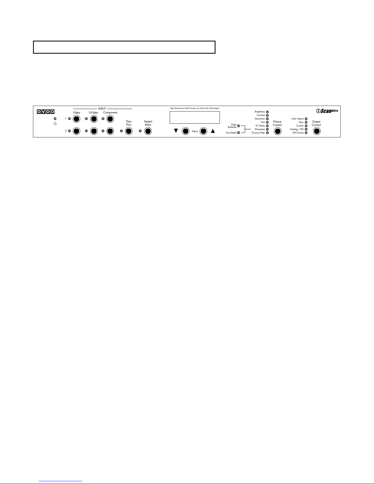
Displays and Controls 10
Power LED 10
Input Select Controls 10
Alphanumeric Display 11
The
▼ and ▲ Adjustment Controls 11
Adjustment Lock 11
Aspect Ratio Control 11
Picture Control 12
Brightness 12
Contrast 12
Saturation 12
Hue 13
YC Delay 13
Sharpness 13
Chroma Filter 13
Output Control 14
Color Space 14
Sync 14
Curtain 14
Analog/DVI 14
DVI Format 14
Remote Control 14
Troubleshooting 15
How It Works 17
Technical Specifications 20
Safety Information 23
Warranty 24
Table of Contents

Welcome to the family of DVDO product owners! Anchor Bay Technologies
is proud and pleased to return this truly great brand name to the marketplace
for video technology users around the globe. It is our pleasure to bring you
the iScan Ultra Video Processor, which we are sure will deliver years of
reliable performance.
First, a bit of history about our company. Anchor Bay Technologies is
composed of the former founding team of DVDO Inc. We are the original
creators of the first DVDO iScan™ Plus Progressive Scan Display Interface,
which revolutionized the video line doubler market starting in 1999. In July
2000, Silicon Image acquired DVDO Inc. and the iScan product line. After
that, Silicon Image introduced and marketed new iScan products, including
the iScan Plus v2, the iScan Pro, and most recently the iScan Ultra. All of
these products have met with universal critical acclaim from reviewers and
from customers alike. Also, all of these products were designed by the original
creators of the DVDO iScan. In April 2003, Anchor Bay Technologies Inc., with
the original DVDO founders as the management team of the new company,
licensed the iScan Video Processor product line and the DVDO® brand name
from Silicon Image. Today, we continue to sell the iScan product line, and we
will be introducing revolutionary new DVDO-branded products in the future.
Thanks again for your purchase of a DVDO-branded product. We look forward
to helping you in any way that we can. Should you need assistance you can
contact us via email or via our toll-free support line. And remember...DVDO by
Anchor Bay Technologies still stands for the highest performance, the best
value, and the best customer support.
It all adds up to digital video done outrageously!
The Anchor Bay Technologies Team
Campbell, California, USA
September 2003
2
Foreword
Thank you for purchasing the iScan
Ultra™ Video Processor, featuring the
world’s most popular video processing
technology as created by the Anchor Bay
Technologies Team. This product delivers
a level of video quality among the very
highest available today.
The carton of your iScan Ultra should
contain the following components:
䊳
iScan Ultra Video Processor
䊳
Universal 6V/2A AC to DC power
converter
䊳
Power cables –
US and UK cords supplied
䊳
Remote control
䊳
Composite video input cable
䊳
S-Video input cable
䊳
Component video input cable
䊳
This Product Guide
Please note that your new iScan Ultra
does not include a video output cable.
The iScan Ultra uses a 15-pin HD-15
(VGA) connector and a DVI connector to
provide video output. You must purchase
an output cable to connect from one of
these outputs to your projector,
HD-compatible TV, or other display
device. Different displays have different
input connectors, so please check your
display specifications to ensure
compatibility. Even though the HD-15
connector is commonly used on personal
computers for RGB video, the iScan Ultra
is capable of outputting either RGB or
Y-Pb-Pr (Component) video formats from
this connector. This is explained in detail
in the Output Control section of this
Product Guide.
3
Introduction

System Requirements
and Compatibility
The iScan Ultra is designed to interface
to displays that can accept a 480p/576p,
31.5KHz progressive scan video signal in
analog RGB or Y-Pb-Pr (Component) video
format, or digital DVI format. These
displays include:
䊳
Projectors
䊳
HDTVs
䊳
Progressive scan and
multi-media TVs
䊳
Plasma TVs
䊳
Computer monitors
If you are not sure if your display is
compatible with the iScan Ultra, please
contact your local iScan dealer. DVDO also
maintains a compatibility list at
www.dvdo.com/faq/faq_compat.html.
This list only shows the devices and
models for which we have received information. If your display is not listed, it
does not necessarily mean it is not compatible, it just means that there is no
compatibility information on it. This
information is the latest available and is
updated periodically as new data are
received by our Technical Support team.
Input Signal Connections
The iScan Ultra accepts three types of
video inputs with two selectable channels
for each type. There is also a single
Pass-Thru input for use with sources for
which no video processing is desired,
or sources that do not provide standard
NTSC/PAL/SECAM interlaced scan
video signals.
The video inputs are:
䊳
Composite video (CVBS),
2 input channels
䊳
S-Video, 2 input channels
䊳
Component video (Y-Pb-Pr),
2 input channels
䊳
Pass-Thru
In general, composite video provides
the lowest image quality due to the
combined nature of the Y (luminance)
and C (chrominance) video signals.
There is a large improvement in image
quality between composite and S-Video,
but the difference between S-Video and
Component video is somewhat less
noticeable.
It is recommended that you use the
Component video inputs for the DVD
player and satellite receiver (or digital
cable box) since these are the highest
quality video sources. VCRs generally
have the lowest image quality, and therefore will not be as affected by the lower
quality of the composite video signal.
The Pass-Thru input is used for analog
video sources that do not require processing such as HDTV satellite broadcasts,
video sources that are already in progressive format or personal computers. This
input allows you to pass these signals
through the iScan Ultra without any
video processing.
4
Installation and Set-Up
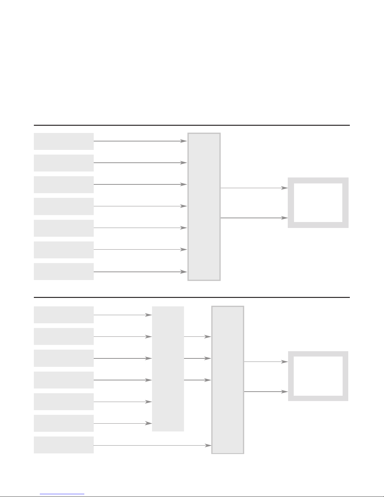
The following diagrams show two typical ways to use the iScan Ultra in a system.
Figure 1a depicts a system where the iScan Ultra is used as the primary video
switcher. Figure 1b depicts a system when the iScan Ultra is used in conjunction
with an A/V Preamplifier/Processor or A/V Receiver.
5
Installation and Set-Up (continued)
Signal Flow
Diagrams
Figure 1a: iScan Ultra
used as the primary video
switching device.
Figure 1b: iScan Ultra used
in conjunction with an A/V
Preamplifier/Processor or
A/V Receiver
VCR or other
Composite video source
Game Console or other
Composite video source
VCR or other
S-Video video source
Set-Top Box or other
S-Video video source
DVD Player or other
Component video source
DVD Player or other
Component video source
Composite Video 1
Composite Video 2 *
S-Video 1 *
S-Video 2*
Component Video 1 *
Component Video 2 *
*
DVI Output
iScan
Ultra
video
processor
DVI Connector
or
Analog Output
HD-15 Connector
Projector, HD-Ready TV,
or other 480/576-p
capable display device
HD-DSS, Progressive
DVD Player, PC, or other
HD video source
VCR or other
Composite video source
Game Console or other
Composite video source
VCR or other
S-Video video source
Set-Top Box or other
S-Video video source
DVD Player or other
Component video source
DVD Player or other
Component video source
HD-DSS, Progressive
DVD Player, PC, or other
HD video source
SD or HD
Component or RGB Video
Composite Video 1
Composite Video 2 *
S-Video 1 *
S-Video 2*
Component Video 1 *
Component Video 2 *
SD or HD
Component or RGB Video
*
Pass Thru Input
AVPreamp
Processor,
AV Receiver,
or other
Video
Switcher
Composite
Video
S-Video
Component
Video
Pass Thru Input
* NTSC/PAL/SECAM interlace only
iScan
Ultra
video
processor
DVI Output
DVI Connector
or
Analog Output
HD-15 Connector
* NTSC/PAL/SECAM interlace only
Projector, HD-Ready TV,
or other 480/576-p
capable display device
The iScan Ultra is usually placed between the display device and any video sources
and acts as a source switch for the display.
6
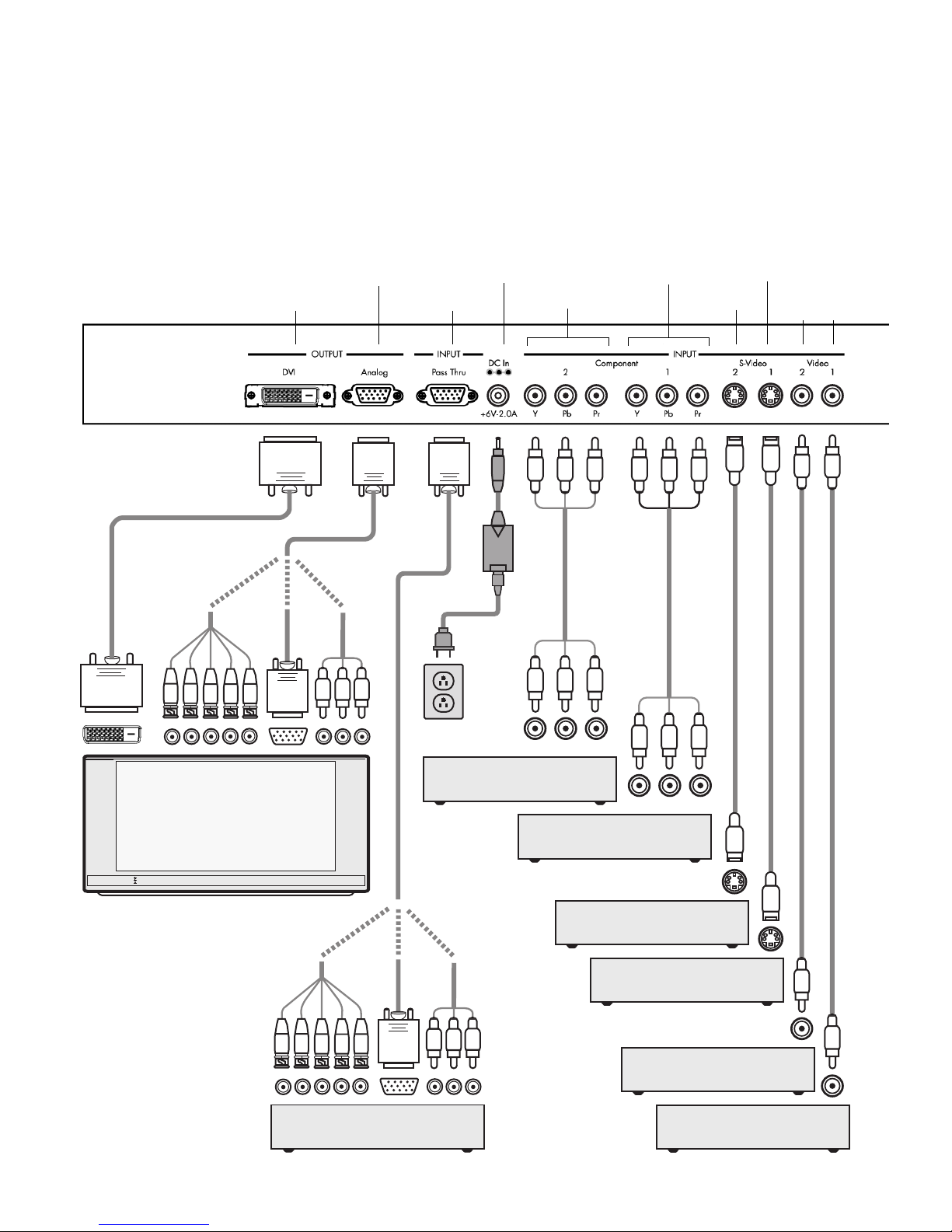
Installation and Set-Up (continued)
Typical System
Configuration
Back of Unit
Progressively Scanned TV or Projector
Y-Pb-Pr
HD-15
HD Satellite TV Tuner, PC, or
Progressive-Scan DVD Player
DVD Player or Other
Component Video Source
DVD Player or Other
Component Video Source
VCR or Other S-Video Source
Set-Top Box or Other
S-Video Source
VCR or Other
Composite Video Source
Video Game or Other
Composite Video Source
Universal
Power
Adaptor
AC Mains
(100-240
VAC
50/60 Hz)
Component Video Cable
Component Video Cable
S-Video Cable
S-Video Cable
Composite Video Cable
Composite Video Cable
Y-Pb-Pr
5x BNC
HD-15
3x RCA
or
or
5x BNC
HD-15
3x RCA
or
or
Back of Unit
DVI-D Interface Cable
HD Video
DVI-D
or
Analog Output 6V DC Power Supply Input Component Video 1 Input S-Video 1 Input
Digital/DVI Output Pass-Thru Input Component Video 2 Input S-Video 2 Input
Composite Composite
Video Video
Input 2 Input 1
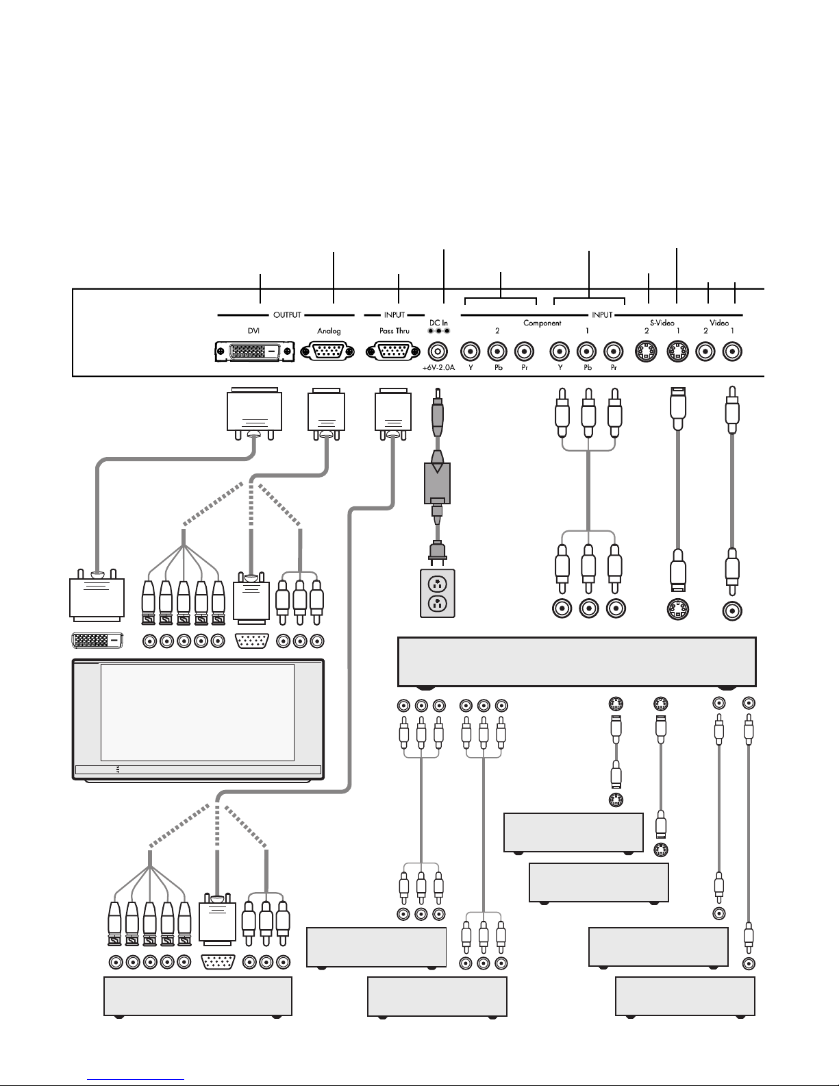
Progressively Scanned TV or Projector
Back of Unit
DVI-D Interface Cable
HD-15
HD Video
HD Satellite TV Tuner, PC, or
Progressive-Scan DVD Player
DVD Player or Other
Component Video Source
DVD Player or Other
Component Video Source
Universal
Power
Adaptor
AC Mains
(100-240
VAC
50/60 Hz)
Component
Video Cable
S-Video Cable
S-Video Cable
S-Video Cable
Composite Video Cable
Composite Video Cable
Composite Video Cable
Y-Pb-Pr
Audio/Video Preamplifier/Processor or AV Receiver
Set-Top Box or
Other S-Video Source
VCR or Other
S-Video Source
Video Game or Other
Composite Video Source
VCR or Other
Composite Video Source
Component Video Cable
Component Video Cable
5x BNC
HD-15
3x RCA
or
or
DVI-D
5x BNC
HD-15
3x RCA
or
or
or
A common variation of this setup is to use an A/V receiver as the switch between all
the sources, with the output of the A/V receiver being the only input to the iScan Ultra.
7
Installation and Set-Up (continued)
Configuration
Variation with
A/V Receiver
Analog Output 6V DC Power Supply Input Component Video 1 Input S-Video 1 Input
Digital/DVI Output Pass-Thru Input Component Video 2 Input S-Video 2 Input
Composite Composite
Video Video
Input 2 Input 1
 Loading...