

DVDO iScanPlus V2 User Manual

L
6FDQ
8VHU0DQXDO
SOXV
Y

L
L
Scan Plus User Manual
7DEOHRI&RQWHQWV
TABLE OF CONTENTS 2
INTRODUCTION 4
IN A NUTSHELL 5
I
NSTALLATION
O
PERATION
5
6
INSTALLATION AND SETUP 7
T
YPICAL CONFIGURATION
S
YSTEM REQUIREMENTS
C
ONNECTIONS
C
OLOR SPACE SELECTION
S
YNCHRONIZATION SIGNALS
8
7
8
10
10
OPERATION 12
I
NPUT SELECTION
A
SPECT RATIO CONTROL
P
ROCESSING MODE INDICATORS
P
OWER USAGE AND ENVIRONMENTAL REQUIREMENTS
12
/ S
QUEEZE MODE
12
13
13
TROUBLESHOOTING 14
HOW IT WORKS 17
B
ACKGROUND
D
EINTERLACING
V
IDEO PROCESSING
17
17
19
TECHNICAL SPECIFICATIONS 20
2

L
L
Scan Plus User Manual
WARRANTY INFORMATION 21
SAFETY INFORMATION: 22
S
AFEGUARDS
P
RECAUTIONS
22
: 22
APPENDIX A – INTERNAL JUMPER SETTINGS 23
R
EMOVING THE ISCAN PLUS V2 MOTHERBOARD
M
ODIFYING COMPOSITE SYNC JUMPER SETTING
M
ODIFYING SYNC-ON-GREEN JUMPER SETTING
M
ODIFYING
R
EASSEMBLING THE ISCAN PLUS V
VCR M
ODE JUMPER SETTING
2 24
23
23
24
24
APPENDIX B – EMI FERRITE SNAP-ON COLLAR 26
Note:
♦
DVDO, PureProgressive,
trademarks of Silicon Image, Inc. This product is covered by pending U.S.
and foreign patents.
L
Scan, iScan, iScan Plus and iScan Plus v2 are
3

L
Silicon Image, Inc.
L
Scan Plus v2 User Manual
,QWURGXFWLRQ
Your iScan Plus v2 package conta ins:
• iScan Plus v2 Line Doubling Upconverter
• Universal power supply module
• Power cable
• Composite input cable
• S-Video input cable
• Warranty card
• User Manual
Your iScan Plus v2 package does not contain an output cable. You will need to get an output
cable that works with your display device. There is more information on these cables in the
Installation section.
The iScan Plus v2 is designed to interface to 31.5 kHz progressively scanned displa y devices such
as:
♦ HDTVs
♦ Progressive scan and Multimedia TVs
♦ Plasma TVs
♦ Data projectors
♦ Home Theater video projectors (31.5KHz scan rate required)
If you are not sure if your display will work with the iScan Plus v2, check the compatibility list on
our web site (www.dvdo.com).
4

L
Silicon Image, Inc.
L
Scan Plus v2 User Manual
,QD1XWVKHOO
If you already know about line doublers and have had experience installing these devices, here’s
a summary of what is unique about the iScan Plus v2.
Installation
The iScan Plus v2 has 3 input ports and 1 output port. The inputs are auto-sensing and switching
which means that they will automatically switch to whichever input is active. The “Input
Priority” switch allows you to select which input should be used when more than one is active.
We recommend using S-Video inputs for DVD players, satellite receivers and/or digital cable
boxes. For VCRs or laserdisc players, chances are good that using the composite video input will
give you a better picture because of the very good Y/C separator in the iScan Plus v2. However,
you should try both composite and S-Video to see which works better in your system.
There are two switches that are of interest during installation. The first, the “Input Priority”
switch was described above. The second is the “Colorspace” select switch on the back panel and
is used to change the output colorspace from RGB to component video (YPrPb), to match the
characteristics of your display device. If your display supports progressive 31.5kHz signa ls on
both RGB and YPrPb inputs, we generally recommend using YPrPb due to the increase color
controls available.
The iScan Plus v2 has a single video output connector which is the same connector used by the
computer industry to connect computer monitors to computers. This connector is called an HD15, or VGA connector and has Red, Green, Blue, H Sync and V Sync signals. However, if
Component Video (YPrPb) colorspace is selected using the colorspace switch, Y, Pr and Pb
signals are placed on the Green, Red and Blue signal pins, respectively.
A high quality VGA-to-VGA computer monitor cable should be used to connect the iScan Plus
v2’s output to devices that can only accept progressive signa ls thr ough a VGA connector.
A standard VGA-to-BNC breakout cable can be used to attach the iScan Plus v2 to any projector
or television that has BNC connec t ors. Your iScan dealer may stock these cables or, if not, they
should be able to recommend a store that does carry them.
A set of three BNC-to-RCA adapters can be used with this same cable for connecting to
televisions with component video RCA inputs. In this case, no sync signals are required so the
gray (or white) and black wires can be left unconnected. These are available at higher-end video
houses or electronics supply stores like Radio Shack.
For RGB devices, the iScan Plus v2 defaults to separate H and V syncs whereas for YPrPb syncon-Y is used. Inside of the iScan Plus v2 there are two jumpers that can be set to enable sync-ongreen and composite sync signals. These are described in Appendix A. These are only needed for
high-end RGB projectors, not for television sets. They are never needed if your display has a
YPrPb input.
A small gray ferrite is shipped with the iScan Plus v2 power supply module. It should be
installed on the end of the small cable coming from the power supply to the iScan Plus v2.
Looping the wire through the ferrite twice in the same direction is an easy way of securing it in
position and will cause the ferrite to be more effective in removing high frequency noise from the
system.
5

L
Silicon Image, Inc.
L
Scan Plus v2 User Manual
Operation
The only switch on the iScan Plus v2 that is not typically limited to installation usage is the
“Aspect Ratio” switch. It is only required for widescreen televisions that have no aspect ratio
control when using the iScan Plus v2.
There are three positions on the Aspect Ratio switch: Normal, Squeeze (black) and Squeeze
(gray). The Normal setting will pass any video input through with no modifications to the aspect
ratio. The two squeeze settings will horizontally compress the video image so that it fits into a
smaller portion of the frame. This will allow a 4:3 aspect ratio image to be displa yed in a 4:3
portion of a 16:9 screen. When squeezing the image, the iScan Plus v2 will put either black or
gray bars on the side of the video. To avoid burn-in, it is strongly recommended that gray bars be
used for all CRT-based, front and rear-screen projectors and normal tube-type televisions. LCD or
DLP-based displays can use the Squeeze (black) setting.
The iScan Plus v2 can be left plugged in and powered-up for years. The V2 has a low-power
(sleep) mode which is activated when there are no video signals that are active at the input
connectors. This mode significantly reduces the power used by the iScan Plus v2.
6
L
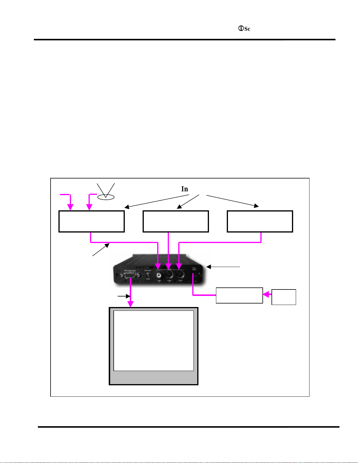
Figure 1: Example Home Theater setup
Input Devices
Display Device
iScan Plus v2
Silicon Image, Inc.
L
Scan Plus v2 User Manual
,QVWDOODWLRQDQG6HWXS
Typical Configuration
Figure 1 shows a typical configuration for a home theater system. In this setup, an iScan Plus v2
is being used to enhance the output from a DVD player, satellite receiver and a VCR before the
selected signal is sent to a rear screen projection TV, or other progressively scanned display
device. Your configuration may be significantly different from this but the basic functional
blocks – input devices, input cables, iScan Plus v2, output cable and display device – will exist in
your system.
One common deviation from this configuration is to use an A/V Receiver or other video
switching device to switch the video signals from the input devices. In this case, the input devices
shown below will be connected to the inputs of the A/V Receiver. The output of the A/V
Receiver will be then be the only input device to the iScan Plus v2.
Cable TV
Antenna
Input
Cables
Output Cable
Progressively
scanned Rear-
screen TV or other
display
DVD Player Satellite Receiver VCR
Power Supply
AC
7

L
Silicon Image, Inc.
L
Scan Plus v2 User Manual
System Requirements
The iScan Plus v2 is designed to interface to progressively scanned display devices that can draw
horizontal scan lines at a rate of 31.5 KHz. Normal televisions operate only at 15.75 KHz but
HDTVs, data projectors, high-frequency video projectors and computer monitors typically
operate at the higher frequency. You should verify that your display is capable of operating at
this horizontal scan rate. Your dealer should be able to help answer this question.
The iScan Plus v2 accepts input from virtually any NTSC video source since it can be driven with
either an S-Video or composite video connection.
Connections
Inputs
There are three available inputs on the iScan Plus v2. Inputs 1 and 2 connect to devices with SVideo outputs. These connections are sometimes c alled S-VHS. Input 3 acce pts input from any
device with an NTSC video output (also called composite video), such as a typical VCR. To
connect a cable or ante nna input, we recommend running that c able to a VCR and using the
composite video output from the VCR to the iScan Plus v2.
We recommend using an S-Video input for a DVD player, satellite receiver and/or digital cable
box. For VCRs or laserdisc players, chances are good that using the composite video input will
give you a better picture because the iScan Plus v2 typically has better Y/C separation circuitry
than most of these devices. However, you should try both composite and S-Video to see which
works better in your system.
The iScan Plus v2 will automatically search for and select whichever of the three input ports is
active. You can also specify a priority-input choice so that if two or more of the inputs are active,
the priority switch indicates which input to use. See the Operation Section for more detail.
Output
In order to connect the iScan Plus v2 to your progressive scan TV, video monitor or projector, you
will need to determine what type of connector and what type of color space is used by your set.
For some types of connections, you will also need to know which wire of the cable needs to be
plugged into which connector on the display device. It is recommended that you also consult
your display owner’s manual for more details about your particular configura tion requirements.
The iScan Plus v2 uses a single 15-pin VGA-style connector for its output. This is the same type of
connector that most computers use to drive compute r monitors. A wide variety of monitors and
projectors can be used with the iScan Plus v2 but you will need to determine which connector
your display device requires, either VGA, BNC, or RCA connector s as described below.
Typical Display Connectors
VGA Connector: One type of input connector that ca n be found on some
TVs and projectors is the same VGA connector used by the iS can Plus v2.
This type of connector is typically found on monitors and projec tors that
are designed to accept input from a computer. High quality male VGAto-maleVGA cables are available through retailers specializing in home
theater or high-end computer stores.
8

Silicon Image, Inc.
L
L
Scan Plus v2 User Manual
9
 Loading...