


 Loading...
ScubaTANK WX
Operation and Maintenance Manual
Document Reference: DOC-WXOM1801

|
Table of Contents |
|
Table of Contents |
|
|
Operation and Maintenance Manual |
|
|
ScubaTANK WX1 and WX2 |
|
|
1. |
Important Safety Information................................................................................................................................. |
3 |
2. |
Specifications ................................................................................................................................................................ |
9 |
3. |
Installation Sequence.............................................................................................................................................. |
11 |
4. |
Booster Set Commissioning ................................................................................................................................. |
17 |
5. |
Operating the Pump Set......................................................................................................................................... |
21 |
6. |
Pressure Vessel.......................................................................................................................................................... |
23 |
7. |
Booster Set User Maintenance ............................................................................................................................ |
25 |
8. XPW Pump Maintenance....................................................................................................................................... |
27 |
|
9. |
Pressure Set Point Adjustment............................................................................................................................ |
29 |
10. Troubleshooting ..................................................................................................................................................... |
31 |
|
11. VASCO V209 and V214 Pump Controllers ................................................................................................... |
37 |
|
Dutypoint Limited
Shepherd Road
Gloucester
GL2 5EL
United Kingdom
2

1. Important Safety Information
1.Important Safety Information
1.1Health & Safety at Work Act 1974
Section 6(a) of this Act requires manufacturers to advise their customers on the safety and the handling precautions to be observed when installing, operating, maintaining and servicing their products. The user’s attention is therefore drawn to the following:
–The appropriate sections of this manual must be read before working on the equipment.
–Installation, operating and maintenance must only be carried out by suitably trained/qualified personnel.
–Normal safety precautions must be taken and appropriate procedures observed to avoid accidents.
Refer to Dutypoint for any technical advice or product information. It is the responsibility of the customer and/or the contractor:
–To ensure that anyone working on the equipment is wearing all necessary protective gear/clothing;
–Is aware of appropriate health & safety warnings and to read the information in this manual.
1.2Safety Messages and Hazard Statement
Table 1.1: |
Hazard Notice Definitions |
|
Message Level |
Definition |
|
|
|
|
DANGER |
|
A hazardous situation which, if not avoided, will result in death or serious |
|
|
injury |
|
|
|
WARNING |
|
A hazardous situation which, if not avoided, could result in death or serious |
|
|
injury |
|
|
|
CAUTION |
|
A hazardous situation which, if not avoided, could result in minor injury or |
|
|
moderate injury |
|
|
|
ELECTRICAL HAZARD |
Risks associated with electricity will cause hazards if not properly avoided |
|
Note |
|
A situation which may arise resulting in undesirable conditions and/or will not |
|
|
cause direct hazards to persons |
|
|
|
1.3Qualified Personnel
WARNING
This product is indented for operation by qualified personnel only
–Only qualified personnel are allowed to install or operate this equipment
–Qualified personnel are defined as trained staff, who are authorised to install, commission and maintain equipment, systems and circuits in accordance with relevant laws and regulations. Personnel must be familiar with the instructions and safety procedures described in this document.
–This product should not be used by anyone with mental disabilities, or anyone without the relevant experience and knowledge, unless they have received instructions on using the equipment and on the associated risks, or are supervised by a responsible person.
–Children must be supervised to ensure they do not play on or around the equipment.
1.4Environmental Protection
All local regulations and codes regarding emissions and waste disposal must be followed. This may include:
–Reporting of emissions to appropriate authorities
–Sorting, recycling and disposal of solid or liquid waste
3

1. Important Safety Information
–Clean-up of spills
–Separate disposal of electrical components from domestic waste
1.5Mechanical Device Servicing
–Familiarise yourself with the relevant contents of this manual
–Installation, maintenance and repair work must only be carried out by trained, skilled and suitably qualified personnel.
–Disconnect or lock-out the power source to ensure that the item(s) will remain inoperative. Locking out the equipment by switching off the release mechanism or set value WILL NOT prevent accidental starting.
–Allow the item(s) to cool if over-heated.
–CLOSE the isolating valves on the suction and discharge connections of the affected item(s).
–If working on pump, VENT slowly and cautiously – Refer to the relevant section of this manual.
–DRAIN the pump(s).
1.6Pump Hand Control Mode (Where Fitted)
In the 'HAND' position the pump(s) controlled by the switch will normally run at full speed and completely independently of any control devices, and can result in pump(s) running against a closed valve head if there is no draw. This can cause the system to be maintained at the maximum pressure produced by the pump plus any incoming pressure and additional pressure caused by water surge and can potentially damage the pump and other parts of the system.
The 'HAND' option should only be used with a competent operator in attendance, or when there is a continued demand sufficient to provide constant flow through the pumps to maintain the running pressure of the system to an acceptable level.
1.7Personal Protective Equipment
Use personal safety equipment according to the site conditions and employer regulations. This may include, but may not be limited to:
–Hard hat
–Safety goggles with side shields
–Protective footwear
–Protective gloves
–Respirator
–Ear protection
–First aid kid
–Safety devices
1.8Precautions Before Commencing Work
Ensure that the following safety precautions are complied with before commencing work:
–Provide a suitable barrier around the work area
–Ensure all safety guards and in place and secure
–Ensure you have a clear path of exit
–Ensure that the product cannot roll or fall over and cause damage to persons or property
–Ensure all lifting equipment is in good condition and rated for the intended task
–Use a lifting harness, safety line and respirator as required
–Allow hot components to cool before handling them
–Ensure that product has been thoroughly cleaned
–Disconnect and lock out power supply, ensuring that it cannot be accidentally re-connected
–Check for any risk of explosion before using hand tools
4

1. Important Safety Information
1.9Precautions During Work
–Never work alone
–Always wear protective clothing and hand protection
–Stay clear of suspended loads
–Always use appropriate lifting devices
–Beware of risks of sudden starts of any automated equipment such as level control
–Beware of starting jerks of electric motors - these can be powerful
–Do not exceed the stated operating limits of equipment
–Do not remove vent plugs from a pressurised system - ensure pressurised components are relieved of pressure before disassembly
–Ensure guards are in place during operation
1.10Hazardous Fluids and Chemicals
If hazardous chemicals come into contact with skin or eyes, use the following procedures:
Condition |
|
Action |
|
|
|
Chemicals or |
1) |
Hold your eyelids apart forcibly with your fingers |
hazardous fluids in |
2) |
Rinse the eyes with eyewash or running water for at least 15 minutes |
eyes |
3) |
Seek medical attention |
|
||
|
|
|
Chemicals or |
1) |
Remove contaminated clothing |
hazardous fluids on |
2) |
Wash the skin with soap and water for at least 1 minute |
skin |
3) |
Seek medical attention |
|
||
|
|
|
1.11Electrical Safety - High Voltages
This information is especially applicable when Variable Speed Controllers (Inverters) are fitted to pumps.
When the inverter variable speed drive head is connected to the power supply the components of the power unit as well as certain components of the master control unit – are also connected to the power supply.
DANGER!
Touching these components can seriously endanger life!
–Before removing the frequency inverter cover, the system must be disconnected from the power supply
–After switching off the power supply wait at least 5 minutes before starting work on or in the inverter drive head - the capacitors in the intermediate circuit must be given time to discharge completely via the discharge restors.
ELECTRICAL HAZARD
Up to 800V can be present - if there are faults this can be higher
–All work carried out when the frequency inverter is open must be performed only by suitably qualified and properly authorised personnel.
5

1. Important Safety Information
ELECTRICAL HAZARD
THE SYSTEM MUST ONLY BE OPERATED WHEN IT HAS BEEN CORRECTLY EARTHED AND PIPES BONDED TO EARTH IN ACCORDANCE WITH IEE REGULATIONS
–When connecting external control wires care must be taken not to short circuit adjacent components. Bare cable ends which are not in use must be insulated.
1.12Electronic Safety Devices
–Inverter drives contain electronic safety devices which switch off the control element in the event of a fault developing.
–A motor can also be stopped by ‘mechanical blocking’
–If it is switched off electronically, the motor is disconnected from the mains voltage supply via the electronics in the inverter drive.
–Voltage fluctuation and power failures (temporary outages) can cause the motor to switch itself off.
WARNING
A motor will have zero current but will remain energised as it stops
–Take necessary precautions - the motor is not voltage-free in the circuit itself
WARNING
Repair of faults can cause items to start up again unexpectedly
–Ensure the motor is isolated before commencing any work
WARNING
High voltage tests of inverters may damage the electrical components.
–Bridge before the incoming/outgoing terminals L-L2-L3 and U-V-W.
–To avoid incorrect metering by capacitors incorporated in the electronic circuits, isolate the motor from the inverter drive head.
1.13Spare Parts
WARNING
Use of non-genuine spare parts may cause damage to equipment, damage to property and voiding of warranty
–Use genuine, Dutypoint-approved spare parts only
–If in doubt, contact Dutypoint Service on 01452 300590.
6

1. Important Safety Information
1.14Transportation and Lifting
WARNING: LIFTING HAZARDS
–Stay clear of suspended loads
–Observe accident prevention regulations in force
–Do not damage the cables during transports; so not squeeze, bend or dray the cable
–Always keeps the cable ends dry
–Secure the unit against tipping over and slipping until it is mounted and fixed in its final location
–Lift and handle the product carefully, using suitable lifting equipment (stacker, crane, crane mounting device, lifting blocks, sling ropes, etc.)
–Always lift the unit by its lifting handle
WARNING: ASSEMBLED SYSTEMS ARE HEAVY
–Failure to properly lift and support this equipment can result in serious physical injury and/or equipment damage,
–Lift equipment only at the specifically identified lifting points.
–Lifting devices such as eye bolts, slings and spreaders must be rated, selected and used for the entire load being lifted
–Select the appropriate lifting points
1)Inspect the package
a)Inspect the package for damage or missing items upon delivery
b)Note any damaged or missing items on the shipping paperwork and contact Dutypoint immediately
c)File a claim with the shipping company if anything is out of order
d)If the product has been picked up at a distributor, file a claim with the distributor
2)Inspect the unit
a)Remove packing materials from the product
b)Dispose of all packing materials in accordance with local regulations
c)Inspect the product to determine if any parts have been damaged or are missing
d)If applicable, unfasten the product by removing any screw, bolts or straps. For your personal safety, be careful when you handle nails and straps.
e)Contact Dutypoint if you have any issues.
1.15Storage
The product must be stored in a covered and dry location free from heat, dirt and vibrations.
NOTE: Protect the product against humidity, heat sources and mechanical damage
NOTE: Do not place heavy weights on the packed product
NOTE: See section on storage limits
7

1. Important Safety Information
8

2. Specifications
2.Specifications
Table 2.2: |
ScubaTANK WX Range Specifications |
|
|
Applications |
Water with no gas or aggressive substances |
|
Flow Range |
0.8 - 3.1 litres/sec |
|
Pressure Range |
2.0 - 7.0 bar |
|
Liquid |
1°C - 23°C |
|
Temperature |
|
|
|
|
|
Ambient |
+5°C - +40°C for indoor installations |
|
Temperature |
|
|
|
|
|
Humidity |
Max 50% |
|
Controller Type |
Modus VASCO |
|
Protection |
Low water level via probe control |
|
Tank Construction |
GRP construction |
|
|
25mm insulation (HCFC and CFC free) |
|
|
Base reinforced with encapsulated multi-ply board and fitted with |
|
|
fixing brackets |
|
|
|
|
Tank Capacity |
175l, 375l, 440l, 490l, 575l, 650l, 750l, 800l, 1,050l, 1,250l, |
|
|
1,650l or 2,250l |
|
|
|
|
Inlet Valve |
¾” or 1” high flow solenoid valve |
|
Discharge |
WX1 models: 1¼” BSP |
|
|
WX2 models: 1½” BSP |
|
|
|
|
Pressure Vessel |
12 litre stainless steel |
2.1Identifying ScubaTANK Models
Figure 2.1: ScubaTANK Model Codes
WX2-5040-490-AB-HS-RM/2
Product Prefix
Number of Pumps
Pump Model
Tank Actual Capacity (litres)
Options: AB = Category 5 AB air gap HS = Horizontally split tank
RM = Control panel supplied loose for remote mounting /2 = Twin Tank System
9

2. Specifications
Table 2.3: |
Pump Ratings |
|
|
|
||
|
Motor kW |
|
Power Supply to |
Power Output from |
|
|
|
|
Control Panel |
Inverter to Pump |
|
Full Load |
|
Pump Model |
Rating |
|
(V/Ph/Hz) |
(V/Ph/Hz) |
|
Current (A) |
|
|
|
|
|
|
|
3040-T230 |
0.55 |
|
230/1/50 |
230/3/50 |
|
4.1 |
3040-T230 |
0.75 |
|
|
|
|
5.2 |
3080-T230 |
1.1 |
|
|
|
|
7.4 |
3100-T230 |
1.5 |
|
|
|
|
5.5 |
5040-T230 |
0.75 |
|
|
|
|
5.0 |
5060-T230 |
1.1 |
|
|
|
|
7.4 |
5080-T230 |
1.5 |
|
|
|
|
10.5 |
5100-T230 |
2.2 |
|
|
|
|
9.0 |
9040-T230 |
1.5 |
|
|
|
|
10.5 |
9060-T230 |
2.2 |
|
|
|
|
11.9 |
9070-T |
3 |
|
400/3/50 |
400/3/50 |
|
5.9 |
9090-T |
3 |
|
|
|
|
6.8 |
Figure 2.2: |
ScubaTANK Components |
|
|
|
||
|
|
|
Pressure |
|
|
|
Inverter |
Control Panel Vessel |
|
|
|
||
|
|
Flexible Connector |
|
|
||
Drives |
|
|
(supplied loose, do not |
|
|
|
|
|
|
|
bend excessively) |
|
|
|
|
|
|
|
Outlet |
|
Pressure |
|
|
|
|
|
|
Transducers |
|
|
Solenoid Valve |
|||
Level Control |
|
|
Isolator and Strainer |
|||
Probes |
|
|
||||
|
|
Incoming Main |
||||
|
|
|
|
|||
|
|
|
|
(¾” or 1” BSP) |
||
Non-Return |
|
|
|
|
|
|
Valves |
|
|
|
|
|
|
Submersible
Pumps
10
3. Installation Sequence
3.Installation Sequence
3.1Position and Secure the Tank
1)Connect the inlet water supply via an isolation valve;
2)Connect the overflow system to a suitable drain;
3)Connect the warning pipe (where fitted) and pipe to a suitable location;
4)Connect the outlet pipe;
5)Connect the electrical supply cable from a fused supply with correct rating - see Table 3.5: ScubaTANK Breaker Ratings;
6)Fill the system and vent the pump;
7)Test and commission.
NOTE: The ScubaTANK must be installed on a stable, level surface or plinth capable of supporting the tank and liquid.
Table 3.4: |
ScubaTANK Dimensions and Weights |
|
|
|||
Tank Size |
Footprint |
Overall |
Height to Top of |
Weight |
Weight |
|
Open Tank |
When |
When Full |
||||
(l) |
|
(mm) |
Height (mm) |
(mm) |
Empty (kg) |
(kg) |
|
|
|
|
|
|
|
175 |
600 |
× 600 |
1414 |
1000 |
59 |
234 |
375 |
600 |
× 900 |
1703 |
1200 |
117 |
492 |
440 |
600 |
× 900 |
1500 |
1200 |
127 |
492 |
490 |
600 |
× 900 |
1703 |
1200 |
117 |
492 |
575 |
600 |
× 900 |
1500 |
1200 |
127 |
492 |
650 |
750 |
× 1200 |
1703 |
1200 |
150 |
800 |
750 |
750 |
× 1200 |
1500 |
1200 |
160 |
800 |
800 |
1160 × 1160 |
1503 |
1000 |
165 |
965 |
|
1050* |
800 × 1500 |
2003 |
1500 |
170 |
1,220 |
|
1250* |
1160 × 1160 |
2003 |
1500 |
194 |
1,444 |
|
1650* |
1160 × 1500 |
2003 |
1500 |
211 |
1,861 |
|
2250* |
1160 × 2000 |
2003 |
1500 |
218 |
2,468 |
|
*Additional overflow warning pipe: ¾” push fit |
|
|
|
|||
NOTE: An additional 250mm minimum clearance is required above the overall height
NOTE: Inlet centre: 62mm below the open tank top height
–The area should be dry, frost-free and well ventilated, away from extremes of temperature. All pipework must be adequately protected from freezing.
–Adequate provision should be made for drainage, leakage damage protection and service access.
–The tank is free standing and is provided with fixing feet for secure fastening to the floor.
3.2Cleaning the Filter
This check is required every 6 months for the first year of operation as the system may still contain sediment. After this, an annual check is normally sufficient to keep the filter clear of sediment.
11

3. Installation Sequence
Figure 3.3: Filter Cleaning Process
1. Turn isolator level to OFF (position perpendicular to pipework)
4. Replace all parts and turn isolator lever to ON position (parallel to pipework)
3. Remove filter and rinse under water to remove build up
2. Remove hex cap and o-ring
3.3Hydraulic Connection
–All pipework must be in accordance with local Water Authority regulations.
–The discharge pipework must be sized according to the system demand.
–All pipework must be securely supported and not over-stressed.
–The overflow and the warning pipe (if fitted) must be piped to a suitable location.
3.4Electrical Supply
WARNING: ALL ELECTRICAL WORK MUST BE CARRIED OUR BY A SUITABLY QUALIFIED PERSON FOLLOWING THE LATEST IEE REGULATIONS
–The system must only be operated when it has been correctly earthed and pipes bonded to earth in accordance with the latest IEE regulations
WARNING: CONTROLLER ELECTRIC SHOCK DANGER. THE CONTROLLER CONTAINS HIGH VOLTAGE
–Never open the controller or work with any electrical connections within it unless the electrical supply to the unit is isolated.
–Wait a further 2 minutes after isolation for the internal circuitry to discharge.
–The electrical supply feed to the ScubaTANK should be a dedicated line to minimise electromagnetic interference.
–The electrical supply rating must be at least double the FLC, assuming all pumps operate together (see Table 3.5: ScubaTANK Breaker Ratings.)
–The control panel isolator cable should be connected via a suitably rated external MCB.
Table 3.5: |
ScubaTANK Breaker Ratings |
|
|
|
||
|
|
|
Single |
|
WX1 (Single |
WX2 (Twin |
|
Pump |
Pump |
Pump |
Twin Pump |
Pump) |
Pump) |
|
ScubaTANK |
ScubaTANK |
Breaker |
Breaker |
||
|
Model |
FLC |
Model |
Model |
Rating |
Rating |
|
|
|
|
|
|
|
|
3040 |
4.1 |
WX1-3040-xxx |
WX2-3040-xxx |
10 (1~) |
20 (1~) |
12
3. Installation Sequence
|
|
Single |
|
WX1 (Single |
WX2 (Twin |
Pump |
Pump |
Pump |
Twin Pump |
Pump) |
Pump) |
ScubaTANK |
ScubaTANK |
Breaker |
Breaker |
||
Model |
FLC |
Model |
Model |
Rating |
Rating |
|
|
|
|
|
|
3060 |
5.2 |
WX1-3060-xxx |
WX2-3060-xxx |
10 (1~) |
20 (1~) |
3080 |
7.4 |
WX1-3080-xxx |
WX2-3080-xxx |
10 (1~) |
20 (1~) |
3100 |
5.5 |
WX1-3100-xxx |
WX2-3100-xxx |
10 (1~) |
20 (1~) |
5040 |
5.0 |
WX1-5040-xxx |
WX2-5040-xxx |
10 (1~) |
20 (1~) |
5060 |
7.4 |
WX1-5060-xxx |
WX2-5060-xxx |
10 (1~) |
20 (1~) |
5080 |
10.5 |
WX1-5080-xxx |
WX2-5080-xxx |
10 (1~) |
20 (1~) |
5100 |
9.0 |
WX1-5100-xxx |
WX2-5100-xxx |
16 (1~) |
32 (1~) |
9040 |
10.5 |
WX1-9040-xxx |
WX2-9040-xxx |
10 (1~) |
20 (1~) |
9060 |
11.9 |
WX1-9060-xxx |
WX2-9060-xxx |
16 (1~) |
32 (1~) |
9070 |
5.9 |
WX1-9070-xxx |
WX2-9070-xxx |
16 (3~) |
32 (3~) |
9090 |
6.8 |
WX1-9090-xxx |
WX2-9090-xxx |
16 (3~) |
32 (3~) |
NOTE: The probe relay settings are factory preset and should conform with information in the wiring diagram. Adjustment will invalidate the warranty.
Figure 3.4: Common Fault Volt Free Contact Wiring Details
MAXIMUM 230V - 5AMP
2× BLACK |
2× RED |
FROM |
FROM |
INVERTER |
INVERTER |
1 |
2 |
3.5How to Seal a Horizontal Split Tank (Applicable to -HS Models)
NOTE: This section applies only to ScubaTANK WX models with horizontal split tanks. These have the -HS designation.
WARNING
The flange sealant is very adhesive
–Ensure it is aligned correctly before applying it to the flange.
–Remove paper backing as you progress along the flanges
–Check that you have the correct number of fixing components, i.e. nut, bolt, washers and arboseal.
–Ensure the flanges are free from grease and grit or other substances which may damage or prevent the flange sealant from sticking,
–Ensure the flange sealant black strip is applied approx 5mm from the inner edge of the flange, water side.
13

3. Installation Sequence
NOTE: Ensure you follow the procedure according the images and instructions below.
Figure 3.5: Applying split tank sealant
Nut and bolt arrangement. Ensure flanges are clean and free from grease, grit etc.
Apply flange sealant ensuring the black strip is water side×.
When applying sealant to the next flange, ensure a overlap.
Flange sealant overlaps like |
DO NOT LEAVE A GAP |
this. |
BETWEEN SEALS |
Note: some sealant may squeeze out from between the flanges. This is normal.
When the flange seals have been applied to the bottom section, the top section of the tank is carefully lifted onto it. A podger/screwdriver may be used to align the bolt holes by pushing it through the top flange hole, through the flange seal and through the lower flange hole. A bolt may be pushed through to hold it in place while the other holes are located. It is recommended that all bolts are pushed through before tightening begins. Recommended torque: 40Nm (30lb/ft)
3.6Bolt Tightening Sequence for Split Tank Flange Assembly
After all the nuts have been spun onto the bolts by hand, you may begin tightening sequentially from the first bolt to its diagonal opposite and continue in a clockwise or anticlockwise direction.
1)First time around, just pinch the nuts with a spanner;
2)Second time around, apply 30% recommended torque;
3)Third time around, apply 60% recommended torque;
4)Fourth time around, apply 100% recommended torque.
3.7Level Probe Details
There are 5 terminals within the probe holder:
14

|
|
|
3. Installation Sequence |
Table 3.6: |
ScubaTANK Level Probe Holder Details |
||
E1 |
Solenoid Cut-Off Probe |
Shortest probe (300mm) |
|
E2 |
Solenoid Cut-In Probe |
100mm longer than the cut out probe |
|
E3 |
Low Level Probe |
50mm shorter than the common probe |
|
E4 |
Common Probe |
Longest probe |
|
E5 |
Note used in standard ScubaTANK models |
|
|
Figure 3.6: ScubaTANK Probes
E1
 E2
E2
E3 E4
E5
E2
E1
E3
E4
Table 3.7: |
ScubaTANK Level Probe Lengths |
|
|
|||
|
|
|
|
|
|
1050, 1250 , |
ScubaTANK Capacity (l) |
175, 800 |
|
375, 490, 650 |
1650, 2250 |
||
|
|
|
|
|
|
|
E4 Common Probe Length (mm) |
PR-6-890 |
- 890mm |
|
PR-6-1090 - 1090mm |
PR-6-1390 - 1390mm |
|
E3 Low Level Probe Length (mm) |
PR-6-840 |
840mm |
|
PR-6-1040 - 1040mm |
PR-6-1340 - 1340mm |
|
E2 Solenoid Cut-In Probe Length |
PR-6-400 |
400mm |
|
PR-6-400 - 400mm |
PR-6-400 - 400mm |
|
(mm) |
|
|
|
|
|
|
|
|
|
|
|
|
|
E1 Solenoid Cut-Out Probe Length |
PR-6-300 |
300mm |
|
PR-6-300 - 300mm |
PR-6-300 - 300mm |
|
(mm) |
|
|
|
|
|
|
|
|
|
|
|
|
|
15

3. Installation Sequence
16

4. Booster Set Commissioning
4.Booster Set Commissioning
4.1Installation and Commissioning Overview
Before shipment, all Dutypoint pump sets are pre-commissioned. Whilst important procedures such as venting and rotational direction checks need to be carried out on site, initial parameters including pressure settings and delay timers will be adjusted to suit the site conditions previously advised to Dutypoint.
In practice, a system can almost invariably be made to perform more efficiently if further re-commissioning is carried out on site.
Please note that engineer visits by Dutypoint are priced at one visit to commission one pump set. If there are multiple units on a site, special terms can be negotiated. To arrange a commissioning visit, please call the Technical Service Help line 01452 300590.
The following checks should be carried out at the initial installation before any run tests are performed.
WARNING
–Ensure that you have read and understood Section 1. Important Safety Information.
4.2Pipework and mechanical components
1)Ensure that the mounting area and any associated groundwork provides adequate support for the pump set.
2)Ensure all supports/brackets are in place and secure.
3)Verify all pipe joints are sealed and tight.
4.3Electrical
WARNING
–These checks MUST be carried out by a competent electrician.
–Ensure that the power source is sufficient to allow the running of two (twin pump sets) or three (triple pump sets) pumps together.
1)Check the motor voltage and frequency information on all the motor nameplates and on controllers etc. correspond with that of the source power supply.
2)Check that all electrical connections are correctly made and secure. Pay particular attention to Earth and bonding connections.
3)Carry out specific checks for Earth bonding.
4)Carry out NICEIC certification checks as required for the installation, e.g Earth Loop Impedance, Insulation Tests, etc.
5)Carry out any other pre-start checks recommended by the pump manufacturer. Refer to the pump manual in the Appendix of this manual. DO NOT POWER UP AT THIS STAGE.
4.4Low Level Float Switch Wiring (Optional)
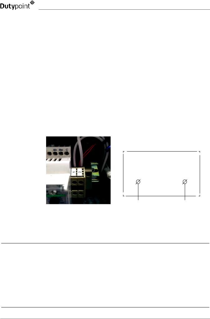
Terminal 1 and 3 require a normally closed contact in order to allow the pump set to operate. To facilitate this the unit will be supplied with a wire loop between 1 and 2. To install a low level float switch this loop has to be removed and the float switch wired to operate as an open on fail scenario.
17
Loading...