


*Gasoline & Propane Tank Not Included
DS10000EH GENERATOR
User Manual
REV: DS10000EH-12192017
This manual provides information regarding the operation and maintenance of these products. We have made every effort to ensure the accuracy of the information in this manual. We reserve the right to change this product at any time without prior notice.
5798 Ontario Mills Pkwy Ontario, CA 91764 USA www.duromaxpower.com
Call our Customer Care Team Toll Free 8-5pm PST Mon-Fri
844-DUROMAX


CONTENTS |
|
|
1. |
Introduction |
|
|
Introduction .................................................................................................................... |
6 |
|
General Safety Procedures ............................................................................................ |
7 |
|
Quick Start Guide (Gasoline) ....................................................................................... |
10 |
|
Quick Start Guide (Propane)........................................................................................ |
12 |
|
Generator Components................................................................................................ |
14 |
|
Package Contents.......................................................................................................... |
16 |
2. |
Generator Setup |
|
|
Shipping Braces ............................................................................................................ |
18 |
|
Wheel Kit Installation.................................................................................................... |
19 |
|
Adding Oil....................................................................................................................... |
20 |
|
Adding Gasoline............................................................................................................. |
21 |
|
Grounding the Generator ............................................................................................ |
22 |
|
High Altitude Operation ............................................................................................... |
22 |
3. |
Starting the Generator |
|
|
Checking the Oil ............................................................................................................ |
24 |
|
Check the Gas Level ..................................................................................................... |
25 |
|
Starting the Generator Using Gasoline....................................................................... |
26 |
|
Starting the Generator Using Propane....................................................................... |
28 |
4. |
Using the Generator |
|
|
AC Usage......................................................................................................................... |
32 |
|
Connecting a Load to the Generator.......................................................................... |
34 |
|
Voltage Selector Switch................................................................................................. |
35 |
|
DC Usage........................................................................................................................ |
36 |
3

CONTENTS |
|
|
5. |
Maintenance and Care |
|
|
Maintenance Schedule.................................................................................................. |
40 |
|
Maintenance Log ........................................................................................................... |
41 |
|
Checking the Oil ............................................................................................................. |
42 |
|
Changing the Oil............................................................................................................. |
43 |
|
Cleaning the Air Filter..................................................................................................... |
44 |
|
Spark Plug Maintenance................................................................................................ |
46 |
|
Emptying the Gas Tank.................................................................................................. |
48 |
|
Cleaning the Fuel Filter Cup.......................................................................................... |
50 |
|
Storage and Transportation.......................................................................................... |
51 |
|
Specifications.................................................................................................................. |
52 |
6. |
Troubleshooting |
|
|
Basic Troubleshooting .................................................................................................. |
54 |
|
Changing / Inspecting the Carbon Brushes ................................................................ |
55 |
|
Changing / Inspecting the AVR ..................................................................................... |
57 |
7. |
Warranty........................................................................................................................... |
62 |
8. |
Contact Information................................................................................................... |
64 |
4


 INTRODUCTION
DuroStar has cemented its reputation as one of the markets leading power equipment companies who are headquartered in the US. All of our products are manufactured to the strictest guidelines and go through countless testing in all phases of production.
Evolving our strong engine line, DuroStar has complemented its offerings to include Pressure Washers, Water Pumps, Engines and now offering V-Twin engines. Reliability is the highest standard we hold ourselves to, whether its powering a heater during a winter storm that knocks out power, dewatering a flooded property, or washing away a deck for the summer season
STOP
Please do not return to store.
Duromax representatives are ready to help you with any questions, concerns, or issues about your new product. We can guide you through assembly, start up, and how to operate your new generator. We want you to be able to put your new generator to use right away!
CALL US BEFORE YOU CONSIDER
RETURNING THE PRODUCT!
TOLL FREE
1-844-DUROMAX
Notice Regarding Emissions
Engines that are certified to comply with U.S. EPA emission regulations for SORE (Small off Road Equipment), are certified to operate on regular unleaded gasoline, and may include the following emission control systems: (EM) Engine Modifications and (TWC) Three-Way Catalyst (if so equipped).
6
 GENERAL SAFETY PROCEDURES
SAFETY ALERT SYMBOL
The safety alert symbol is used with one of the safety words (DANGER, CAUTION, or WARNING) to alert you of hazards. Please pay attention to these hazard notices both in this manual and on the generator.
Please familiarize yourself with the following safety symbols and words:
●● DANGER: Indicates a hazard that will result in serious injury or death if instructions are not followed.
●● WARNING: Indicates a strong possibility of causing serious injury or death if instructions are not followed.
●● CAUTION: Indicates a possibility of personal injury or equipment damage if instructions are not followed.
DANGER: This generator produces poisonous carbon monoxide gas when running. This gas is both odorless and colorless. Even if you do not see or smell gas, carbon monoxide may still be present. Breathing this poison can lead to headaches, dizziness, drowsiness, and eventually death.
●● Use outdoors ONLY in non-confined areas.
●● Keep several feet of clearance on all sides to allow proper ventilation of the generator.
WARNING: The exhaust from this product contains chemicals known to the State of California to cause cancer, birth defects, or other reproductive harm.
WARNING: This generator produces heat when running. Temperatures near exhaust can exceed 150°F (65°C).
●● Do not touch hot surfaces. Pay attention to warning labels on the generator denoting hot parts of the machine.
●● Allow generator to cool several minutes after use before touching engine or areas which heat during use.
7

 GENERAL SAFETY PROCEDURES
 WARNING: This generator may emit highly flammable and explosive gasoline vapors, which can cause severe burns or even death. A nearby open flame can lead to an explosion even if not directly in contact with gas.
●● Do not operate near an open flame.
●● Do not smoke near generator.
●● Always operate on a firm, level surface. ●● Always turn generator off before refueling.
●● Allow generator to cool for at least 2 minutes before removing fuel cap. Loosen cap slowly to relieve pressure in tank.
●● Do not overfill gas tank. Gas may expand during operation. Do not fill to the top of the tank.
●● Always check for spilled gas before operating.
●● Empty the gasoline tank before storing or transporting the generator.
●● Before transporting, turn fuel valve to the off position and disconnect the spark plug.
WARNING: This generator produces a powerful voltage, which can result in electrocution.
●● ALWAYS ground the generator before using it (see the “Grounding the Generator” portion of the “PREPARlNG THE GENERATOR FOR USE section).
●● Generator should only be plugged into electrical devices, either directly or with an extension cord. NEVER connect to a building electrical system without a qualified electrician. Such connections must comply with local electrical laws and codes. Failure to comply can create a backflow of power, which may result in serious injury or death to utility workers.
●● Use a ground fault circuit interrupter (GFCI) in highly conductive areas such as metal decking or steel work. GFCls are available in-line with some extension cords.
●● Do not use uncovered in rainy or wet conditions. ●● Do not touch bare wires or receptacles (outlets).
●● Do not allow children or non-qualified persons to operate.
8

 GENERAL SAFETY PROCEDURES
In addition to the above safety notices, please familiarize yourself with the safety and hazard markings on the generator.
9
 QUICK START GUIDE (GASOLINE)
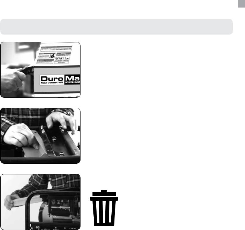
1. Remove shipping braces
The shipping braces prevent engine movement during shipment. Flip the generator over and remove the brightly colored brace between the motor and the frame, and the wood brace under the generator.
2. Add oil
The oil fill cap is located on the lower engine block to the right of the recoil start housing. Remove the oil fill cap and fill with 10w30 oil.
3. Add gasoline
The fuel cap is located on top of the fuel tank. Fill the tank with fresh unleaded gasoline 87 octane or higher. The tank isfullwhenyouseefuelinthebottomofthefuelfiltercup. DO NOT overfill the tank.
4. Turn breaker off
The breaker is located on the right side of the front power panel. Flip the breaker down to prevent accidental load when starting the generator.
5. Turn gas valve on
The gas valve is located above the recoil start on the bottom of the fuel tank. Rotate the valve clockwise to the vertical position to turn on the gas supply.
10
6. Close choke
The choke lever is located above the air filter to the right of the recoil start. Slide the lever to the left to cut the air supply and allow more gas into the engine to start.
7. Start generator
The key switch is located on the left side of the front power panel. Insert the key and turn to the start position to start the generator. Allow the key to return to the run position once started.
8. Open choke
The choke lever is located above the air filter to the right of the recoil start. Slide the lever to the right to open the choke and increase air into the carburetor for normal running.
9. Turn breaker on
The breaker is located on the right side of the front power panel. Flip the breaker up to allow power to flow to the receptacles.
10. Connect devices
Connect your devices to the receptacles on the front panel.
Start with the largest loads first.
11
 QUICK START GUIDE (PROPANE)
1. Remove shipping braces
The shipping braces prevent engine movement during shipment. Flip the generator over and remove the brightly colored brace between the motor and the frame, and the wood brace under the generator.
2. Add oil
The oil fill cap is located on the lower engine block to the right of the recoil start housing. Remove the oil fill cap and fill with 10w30 oil.
3. Turn breaker off
The breaker is located on the right side of the front power panel. Flip the breaker down to prevent accidental load when starting the generator.
4. Turn gas valve off
The gas valve is located above the recoil start on the bottom of the fuel tank. Rotate the valve counter clockwise to the horizontal position to stop the flow of gasoline to the carburetor.
5. Connect propane hose
The propane regulator / decompression valve is located on the frame of the generator below the OHV valve cover. Ensure the propane hose is securely connected to the regulator/compression valve.
12

6. Connect propane tank
The propane hose is located on the left side of the regulator, below the OHV valve cover. Screw the open ACME nut connection to your propane tank and turn the tank on.
7. Release propane pressure
The propane regulator / decompression valve is located on the frame of the generator below the OHV valve cover. Press the button in the center down 3-5 times for one secondtocleartheairfromthelinesandfillthecarburetor.
8. Adjust choke
The choke lever is located above the air filter to the right of the recoil start. Slide the lever to the right to open the choke and increase air into the carburetor for normal running.
9. Start
The key switch is located on the left side of the front power panel. Insert the key and turn to the start position to start the generator. Allow the key to return to the run position once started.
10. Turn breaker on / connect
The breaker is located on the right side of the front power panel. Flip the breaker up to allow power to flow to the receptacles. Connect your devices to the receptacles on the front panel. Start with the largest loads first.
13
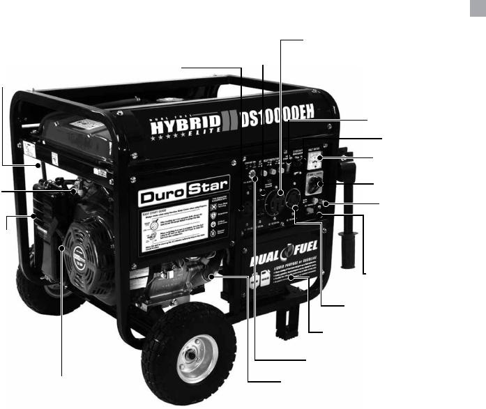
 GENERATOR COMPONENTS
|
8. 120v 3-Prong |
22. 120/240v 4-Prong |
|
Receptacle |
|
21. 120V 3 Prong |
Receptacle |
2. Choke Lever |
Twist Lock |
|
|
||
|
23. Auto Throttle |
|
|
5. Circuit Breaker |
|
|
10. Volt Meter |
|
16. Fuel Valve |
1. Power Boost |
|
7. Ground |
||
|
||
|
Terminal |
|
1. Air Filter |
|
|
|
11. 12v DC |
|
|
Charging Posts |
|
|
6. 120/240v 4-Prong |
|
|
Twist Lock |
|
9. Battery |
|
13. Engine Switch |
14. Recoil Start |
12. Oil Fill and Dipstick |
|
1.Air Cleaner - a removable, cleanable, oiled, element that cleans the air going into the engine.
2.Choke Lever - Allows the airflow into the carburetor to be restricted to assist in starting the engine.
3.Fuel Gauge - Indicates the amount of fuel in the gasoline tank.
4.Fuel Cap - Allows access to fill the gasoline tank.
5.Circuit Breaker - Resettable switch that protects the generator from electrical overload.
6.120/240v 4-Prong Twist Lock - Use to connect electrical devices that run 120 or 240 Volt, 60Hz, single phase, AC current (NEMA L14-30).
7.Ground Terminal - Connect a ground wire here to properly ground the generator.
8.120v 3-Prong Receptacle - Use to connect electrical devices that run 120 Volt, 60 Hz, single phase, AC current (NEMA 5-20).
9.Battery - 12V DC 7ah Battery that powers the Electric Start System.
10.Volt Meter - Provides reading of voltage output.
11.12v DC Charging Posts – DC Output for charging batteries or running small DC powered items.
14

15. Fuel Filter Cup
3. Fuel Gauge
4. Fuel Cap
 17. Spark Plug
18. Muffler 
20. Pressure
Release
Valve
19. Propane Connector
12. Oil Fill and Dipstick - Use to add or check the oil.
13. Engine Switch – 3 Position Switch to “Start”, “Run”, or turn “Off” the generator.
14. Recoil Start – Easy Pull Recoil Start to start the engine without the electric start. 15. Fuel Filter Cup - Traps dirt and debris in gasoline before it enters the engine. 16. Fuel Valve - On/Off Valve that allows fuel into the engine.
17. Spark plug – Provides ignition to the engine.
18. Muffler – Reduces engine emissions and reduces noise.
19. Propane Tank Connector and Hose – Connects the LPG tank to the LPG Regulator.
20. Propane Regulator and Pressure Release Valve - Provides a regulated LPG Fuel supply to the engine. (Intended for use with a LPG Source of 3 PSI or more.)
21. 120v 3-Prong Twist Lock - Use to connect electrical devices that run 120 Volt, 60 Hz, single phase, AC current (L5-30).
22. 120/240v 4-Prong Receptacle - Use to connect electrical devices that run 120 or 240 Volt, 60Hz, single phase, AC current (NEMA 14-50).
23. Auto Throttle - Allows the engine to run at reduced speed when no load is present to save on
fuel and reduce noise levels.
15

 PACKAGE CONTENTS
Your generator comes with the items listed below. Please check to see that all of the following items are included with your generator.
Double Sided
Screw Driver
Phillips and slot blade screwdriver used for generator maintenance.
Spanner |
Spark Plug Wrench |
Assorted wrenches used in |
Used in spark plug |
generator maintenance and |
maintenance, inspection, and |
assembly. Commonly 8mm, |
installation. |
10mm, 13mm, and 15mm. |
|
Oil Funnel w/ hose |
DC Charge Cables |
Plug Ends |
Used to add oil to the |
Used in conjunction with the |
Plug heads for the receptacles |
generator without messy spills. |
charging posts to charge 12v |
found on the generator are |
|
automotive style batteries or |
included to make or rewire |
|
small DC appliances. |
your own cords. |
●● Note: Actual tools may differ in appearance or design from image shown.
16

GENERATOR SETUP
Proper setup of your generator will get you going as soon as possible while making sure you and your equipment are safe and cared for.
 GENERATOR SETUP
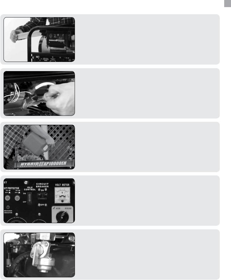
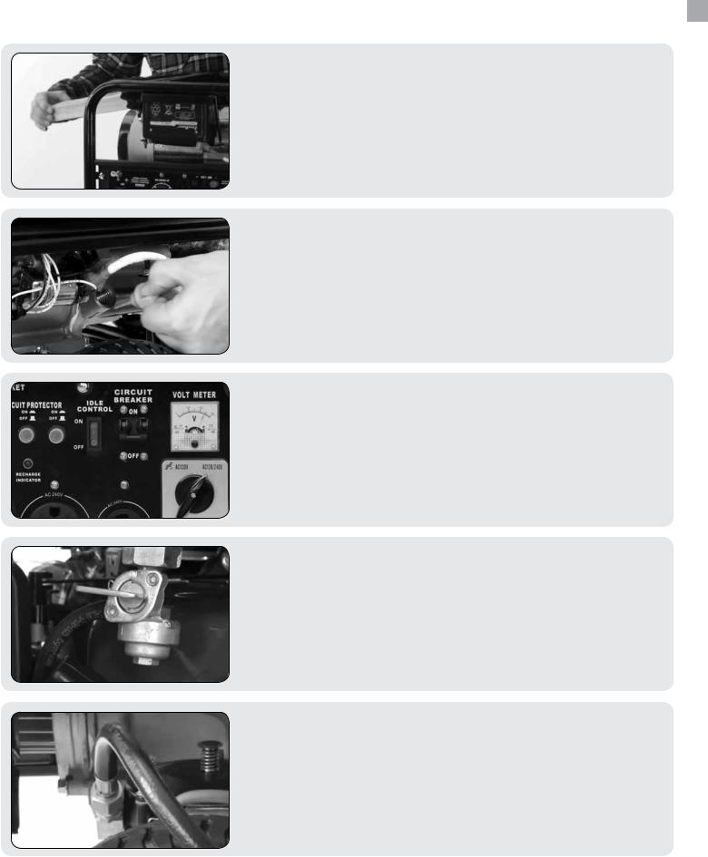
Step 1 - Remove Shipping Braces
1.Unpack
a.Remove the generator from the box.
b.Place the largest piece of packing foam on a flat surface.
c.Flip the generator upside down on the pad.
CAUTION: NEVER Attempt this if you have put fuel or oil in the generator.
2.Remove braces
a.Completely remove each of the 4 bolts holding the orange metal brace in place.
b.Remove the brace.
c.Cut the nylon tie strap holding the wood brace in place.
d.Grab the end of the second brace and pull it out.
e.This piece is no longer needed and can be discarded.
Note: Shipping braces can be thrown away.
They will not be needed again.
18
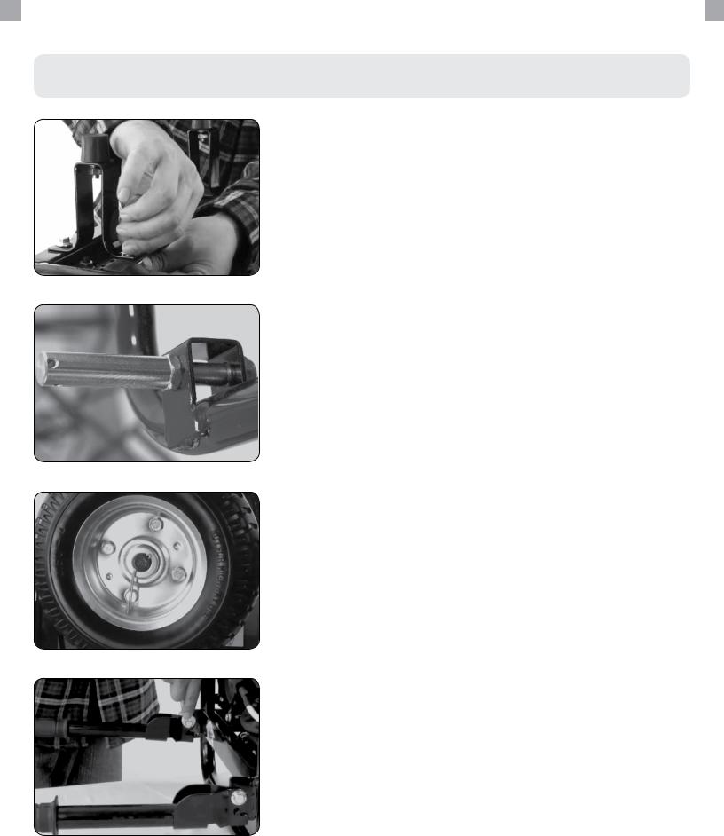
Step 2 - Wheel Kit Installation (Optional)
1. Install support legs
Secure the support legs to the frame with provided bolts and lock nuts.
2.Install wheels
a.Insert wheel bolt through frame and secure with provided nut.
b.Slide one wheel over each axle end and secure with the provided retaining pins.
3.Install Handles
Attach the handles to the brackets on the frame using the provided bolts and nuts.
Do not over tighten the handles, it will prevent free movement.
19
 GENERATOR SETUP (CONTINUED)
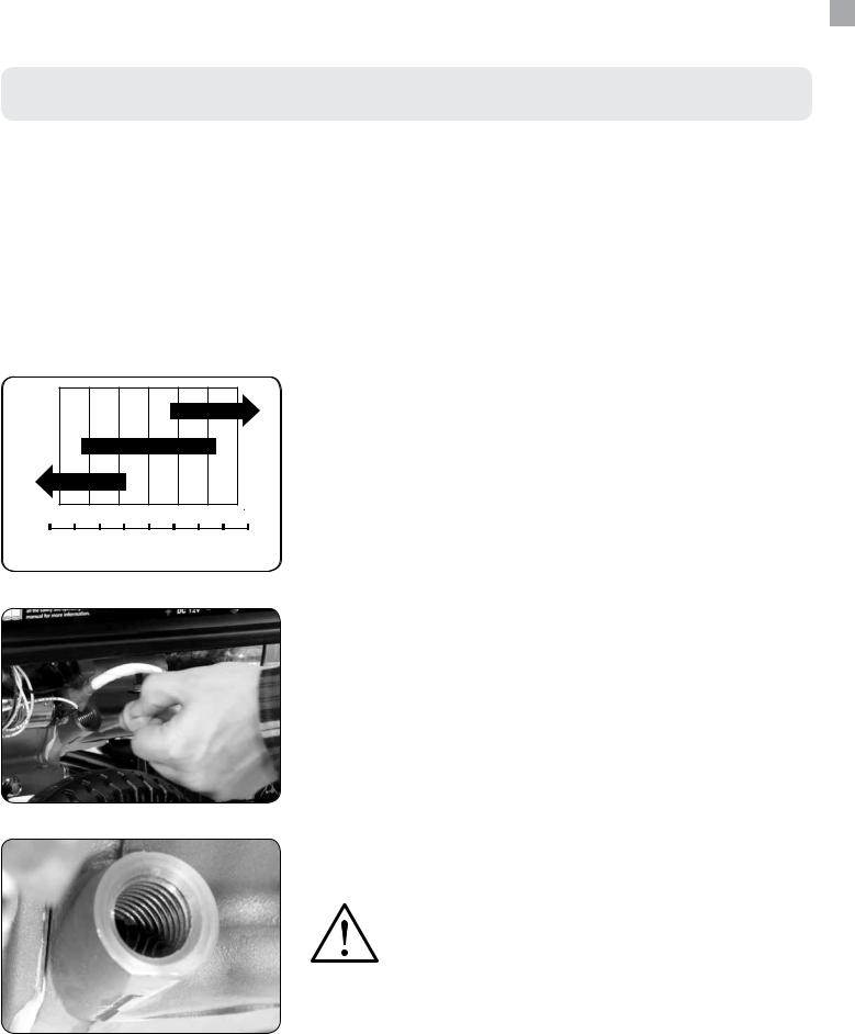
Step 3 - Adding Oil
The generator requires engine oil to operate properly. The generator, when new from the package contains no oil in the crankcase*. You must add the proper amount of oil before operating the generator for the first time. This amount is equal to the oil capacity of the engine crankcase:
Model Number |
DS10000EH |
|
|
Engine Oil Capacity |
37 fl. oz (1.1L) |
|
|
WARNING: Do not apply engine oils with additives or 2-stroke gasoline engine oils. They don’t have enough lubrication, and may shorten the engine’s service life.
SAE
30
10W-30
5W-30
-20 |
0 |
20 |
40 |
60 |
80 |
100 F |
-40 -30 -20 -10 0 10 20 30 40 C
C
ENVIRONMENTAL TEMPERATURE
Engine oil recommended: SAE 10W-30. Viscosity varies with regions and temperatures. Choose your oil viscosity using the chart to the left.
* A small amount of oil from factory testing may be present on arrival.
1.Add oil
a.Make sure the generator is on a level surface.
b.Unscrew the oil filler/dipstick cap from the engine .
c.Using a funnel, add the appropriate amount of oil into the crankcase. You will know the crankcase is full when the oil level has reached the lower lip of the opening you have just poured the oil into.
d.Replace oil filler cap.
WARNING: DO NOT overfill the crankcase. This may damage the motor and shorting overall life of your generator.
20
 Loading...