

Page 1
Operating and Service Manual
6200 SXT Automatic Manganese Greensand Filter (ISF)
Made in Canada
Page 2
Introduction
Read this Manual First
• Read this manual thoroughly to become familiar with the device and its capabilities before installing or operating your
Water Filter. Failure to follow instructions in this manual could result in personal injury or property damage. This manual will
also help you to get the most out of your filter.
• This system and its installation must comply with state and local regulations. Check with your local public works depart-
ment for plumbing and sanitation codes. In the event the codes conflict with any content in this manual the local codes
should be followed. For installations in Massachusetts, Massachusetts Plumbing Code 248 CMR shall be adhered to. Consult your licensed plumber for installation of this system.
• This water softener is designed to operate on pressures of 20 psig 125 psig. If the water pressure is higher than the maxi-
mum use a pressure reducing valve in the water supply line to the filter.
• This unit is capable of operating at temperatures between 40°F and 110°F (4°C - 43°C). Do not use this water filter on hot
water supplies.
• Do not install this unit where it may be exposed to wet weather, direct sunlight, or temperatures outside of the range
specified above.
• Do not use water that is microbiologically unsafe without adequate disinfection before or after this system.
• This publication is based on information available when approved for printing. Continuing design refinement could cause
changes that may not be included in this publication. WaterGroup reserves the right to change the specifications referred
to in this literature at any time, without prior notice.
Safety Messages
Watch for the following safety messages in this manual:
NOTE: used to emphasize installation, operation or maintenance information which is important but does not
present a hazard.
Example: NOTE: Check and comply with you state and local codes. You must follow these guidelines.
CAUTION: used when failure to follow directions could result in damage to equipment or property.
Example:
CAUTION! Disassembly while under pressure can result in flooding.
WARNING: used to indicate a hazard which could cause injury or death if ignored.
Example:
WARNING! ELECTRICAL SHOCK HAZARD! UNPLUG THE UNIT BEFORE REMOVING THE COVER OR ACCESSING
ANY INTERNAL CONTROL PARTS
NOTE: Do not remove or destroy the serial number. It must be referenced on request for
warranty repair or replacement
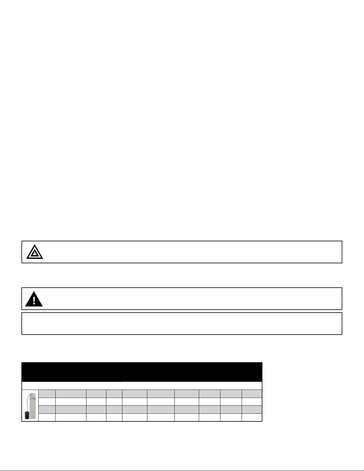
Specification
Unit †
Item # Model #
4636 DISF75SXT 8 X 47 0.75 4 5 3.5 120 2 oz 4500
4637 DISF10SXT 10 X 47 1 5 6 5 150 4 oz 6000
4638 DISF15SXT 12 X 52 1.5 8 9 7 180 6 oz 9000
4639 DISF20SXT 14 X 50 2 10 11 10 265 8 oz 12000
• At the stated service flow rates, the pressure drop through these devices will not exceed 15 psig.
• Changing salt settings from factory setting may require changing injector sizes to achieve stated capacities
• The manufacturer reserves the right to make product improvements which may deviate from the specifications and descriptions stated herein, without obligation to change previously manufactured products or to note the change.
* Do not use water that is microbiologically unsafe without adequate disinfection before or after the system.
Peak flow rates intended for intermittent use only (10 minutes or less) and are for residential applications only. Do not use peak flow rate for commercial applications or for a continuous rate when treated water supplies are geothermal heat pump,
swimming pool, etc.
†
USA customers will need to add “-4” to the item numbers for ordering.
Tank
Size
Media
(CF)
Service
Flow
Rate (gpm)
Duro Twin Tank Softeners
Peak Service
Flow Rate
(gpm)
Backwash
Flow Rate
(gpm)
Shipping
Weight
(lbs)
Pot Perm
per
Regen
Iron
Capacity
(ppm)
Working Temperature = 34-110°F (1-43°C)
(Do not subject the unit to freezing temperatures)
Working Pressure = 20-125 PSIG (137-861 kPa)
Voltage = 120V / 60 Hz
Pipe Size = 3/4”
** Potassium Permanganate Feeder come unloaded.
Potassium Permanganate sold separately.
Page 3
How a Duro Manganese Greensand Filter Works
Your automatic iron filter is an ingeniously simple and reliable design. The unit consists of a bed of filter media contained
in a fiberglass tank; a specially designed feeder containing potassium permanganate for the regeneration of the filter
and a proven automatic control. Raw water enters your home through the main supply line, enters your iron filter and passes
down through the filter media. Any iron, manganese or hydrogen sulfide present in your water supply is exposed to oxygen
stored in the filter media. The oxygen causes precipitation of the minerals and they are trapped in the filter media. Only
clean filtered water flows to your household water line. The filter media is periodically regenerated, automatically backwashing the trapped minerals to the drain and replacing the oxygen. This is done by introducing potassium permanganate
to the media.
1. Your automatic iron filter can be programmed to operate according to your needs by making the appropriate settings on
the timer. On the days your filter regenerates, the operating cycles will be automatically performed. In the service position, filtered water is supplied for household use.
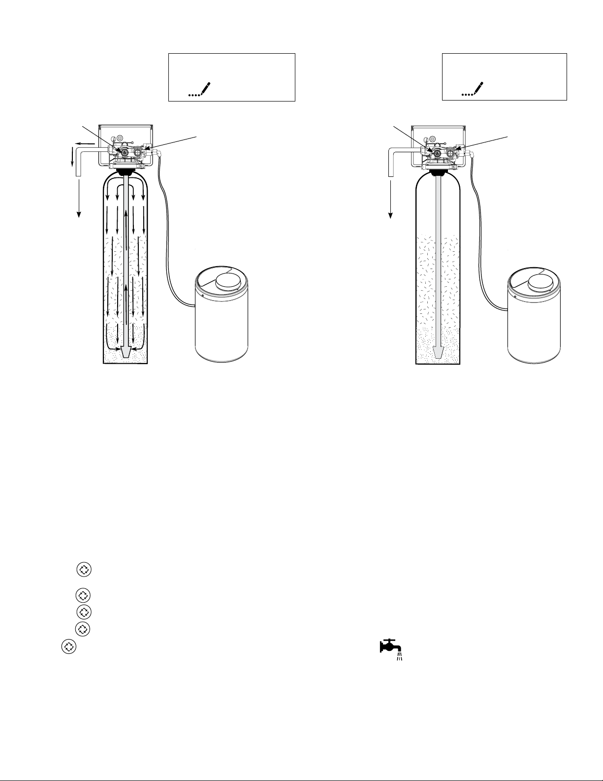
2. The automatic control reverses the flow of the water through the filter, backwashing minerals trapped in the filter
to the drain.
3. The control pulls a vacuum on the feeder. This causes an exact volume of saturated potassium permanganate solution to
be drawn into the filter tank.
4. The control slowly rinses the chemical through the media tank. The potassium permanganate supplies oxygen to the filter
media.
5. The control fast rinses the media bed to settle it and to ensure that all the chemical and mineral precipitate is removed.
6. The control adds water to entirely fill the previously evacuated feeder. The feeder is now ready for the next regeneration.
The control puts the system into service, supplying iron-free water to the household. All this is performed automatically over
a period of 2 ¾ hours. Water runs to the drain for approximately 80 minutes
The water softener can run for days before running out of sodium, and when it does, the sodium is replenished
in only a matter of a few hours.
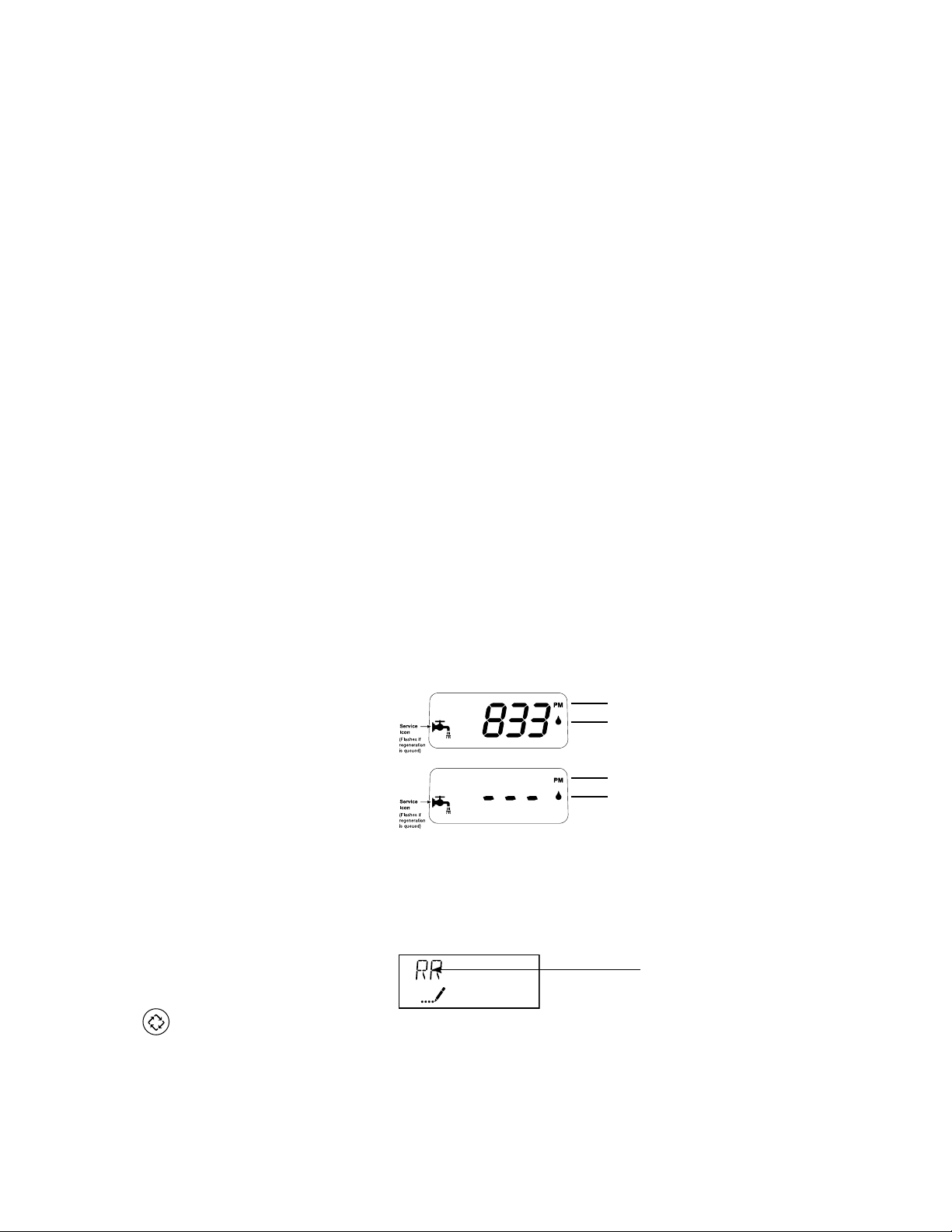
In normal operation, the Time of Day display will alternate being viewed with the Volume Remaining display. This display will
be in gallons or liters. As treated water is used, the Volume Remaining display will count down from a maximum value to zero
or (---). Once this occurs, a regeneration cycle will be initiated at the Set Regeneration Time. Water flow through the valve is
indicated by the Flow Indicator that will flash in direct relationship to flow rate.
Example 833 Gallons of Treated
Water Remaining
0 Gallons of Treated
Water Remaining
PM Indicator
Flow Indicator
(Flashing with water flow)
PM Indicator
Flow Indicator
(Flashing with water flow)
Timer Behavior During Regeneration
In regeneration, the control will display a special regeneration display. In this display, the control will show the current
regeneration step abbreviation the valve is advancing to or has reached and the time remaining in that step. The step
abbreviation displayed will flash until the valve has completed driving into this regeneration step position. Once all
regeneration steps have been completed, the valve will return to Service and resume normal operation.
Example Less than 6 minutes
remaining in Regeneration
Step Rapid Rinse
Pushing the
resume normal step timing.
during a regeneration cycle will immediately advance the valve to the next cycle step position and
5
Regeneration Step
Abbreviation
Please see the control valve manual for different regeneration step abbreviations.
2
Page 4
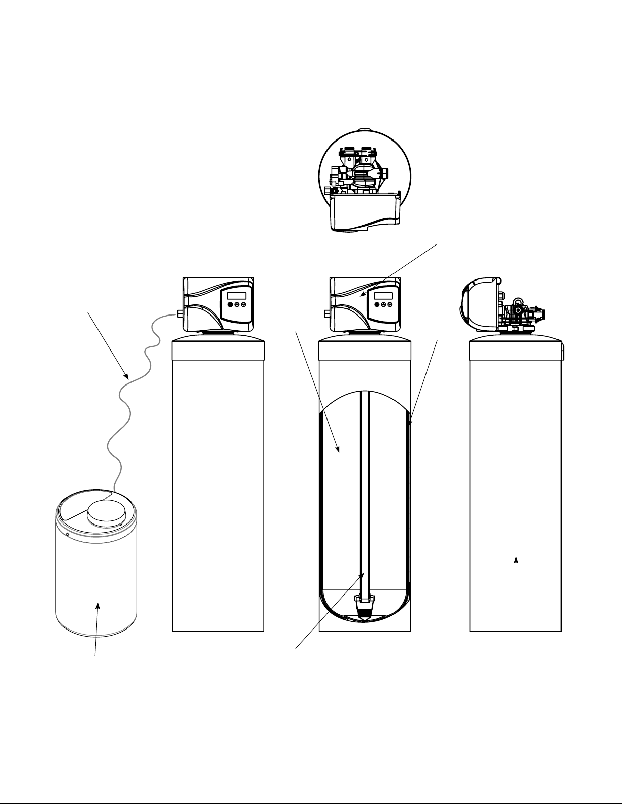
Familiarize yourself with the unit and components
Feed Line to Valve
Control Valve
Media
Tank
Chemical Feeder
Distributor/Riser
3
4
Tank Jacket
Page 5

Sizing and Operating Requirements
Water Pressure
The water system must have a pump big enough to deliver the recommended backwash rate with a minimum pressure at
the inlet of the filter of 20 psi (137 kPa). If the existing system cannot do this, it must be upgraded to do so. Whenever possible, the water system should be adjusted to deliver at least 30 psi (206.8 kPa) for even more satisfactory results. Maximum
pressure should not exceed 100 psi (689 kPa).
Backwash Flow Rates
The most important criteria in sizing an iron filter is the capacity of the pump. The water must pass through the filter media at
a service flow rate that allows it to oxidize and collect the iron. The filter must also be backwashed at a flow rate sufficient
to dislodge and remove the captured iron. Failure to provide sufficient water will cause a build-up of iron in the filter media,
impairing its iron removing ability and resulting in iron bleeding out into the service water. In order for your filter to backwash
and rinse properly, your pump must be capable of providing the backwash flow rates indicated in the above specification
chart.
Capacity
An iron filter with one cubic foot of filter media regenerated with one Potassium Permanganate feeder will work well for
most residential applications. For example, with iron in the range of 3-6 ppm, most filters will need to regenerate every two
or three days providing an average family size of four or five people. The specification chart above shows the iron removal
capacity in ppm that can be expected on automatic iron filters. The specifications are based on obtaining 6,000 ppm of
capacity for each cubic foot of filter media. Two different Potassium Permanganate feeders are available – one feeding
2 oz. per regeneration, the other feeding 4 oz. In order to obtain the above capacities, the pH of the water being treated
must be 7.0 or above. In the event the water is below 7.0, it must be treated with the appropriate equipment before going
through the filter.
Removal of Iron, Manganese & Hydrogen Sulfide
For the purpose of sizing a filter, consider 1 ppm of manganese equal to 2 ppm of iron and 1 ppm of hydrogen sulfide equal
to 3 ppm of iron. Manganese and hydrogen sulfide (sulfur) are more difficult to oxidize than iron. Therefore, we suggest that,
when making your sizing calculations and regeneration frequency calculations, calculate iron x 1, manganese x 2 and hydrogen sulfide x 3. All three must equal less than 10 ppm. Manganese is often present in water when iron is present. Hydrogen sulfide can normally be identified by a strong rotten egg odor
4
5
Page 6
Installation Instructions
Contact your local distributor to use WaterGroup laboratory for complete water analysis free of cost and no
obligation to you.
All government codes and regulations governing the installation of these devices must be observed.
.
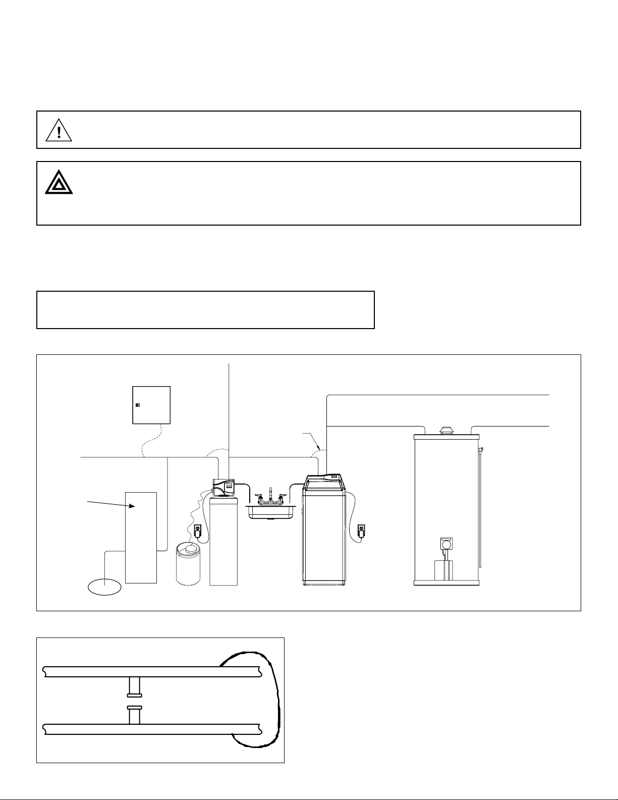
If the ground from the electrical panel or breaker box to the water meter or underground copper pipe is tied
to the copper water lines and these lines are cut during installation of the Noryl bypass valve and/or poly
pipe, an approved grounding strap must be used between the two lines that have been cut in order to maintain continuity. The length of the grounding strap will depend upon the number of units being installed and/or
the amount of copper pipe being replaced with plastic pipe. See Figure 1.
In all cases where metal pipe was originally used and is later interrupted by poly pipe or the Noryl bypass valve as in Figure
1 or by physical separation as in Figure 2, an approved ground clamp with no less than #6 copper conductor must be used
for continuity, to maintain proper metallic pipe bonding.
NOTE: Check your local electrical code for the correct clamp.
Figure 1
Raw Water
To Outdoors
Pressure Tank
Pump
Figure 2
Electrical Panel
Hard
Filtered
Water
Iron Filter
Ground Strap
Drain
Drain
Softener
Cold Soft Water
Hard Soft Water
Water Heater
Unfiltered Water Bypass
Loop Cut & Capped
Filtered Water Line in Home
Ground Strap Required
Because of Break in Continuity
5
Page 7
D
C
B
Preparations
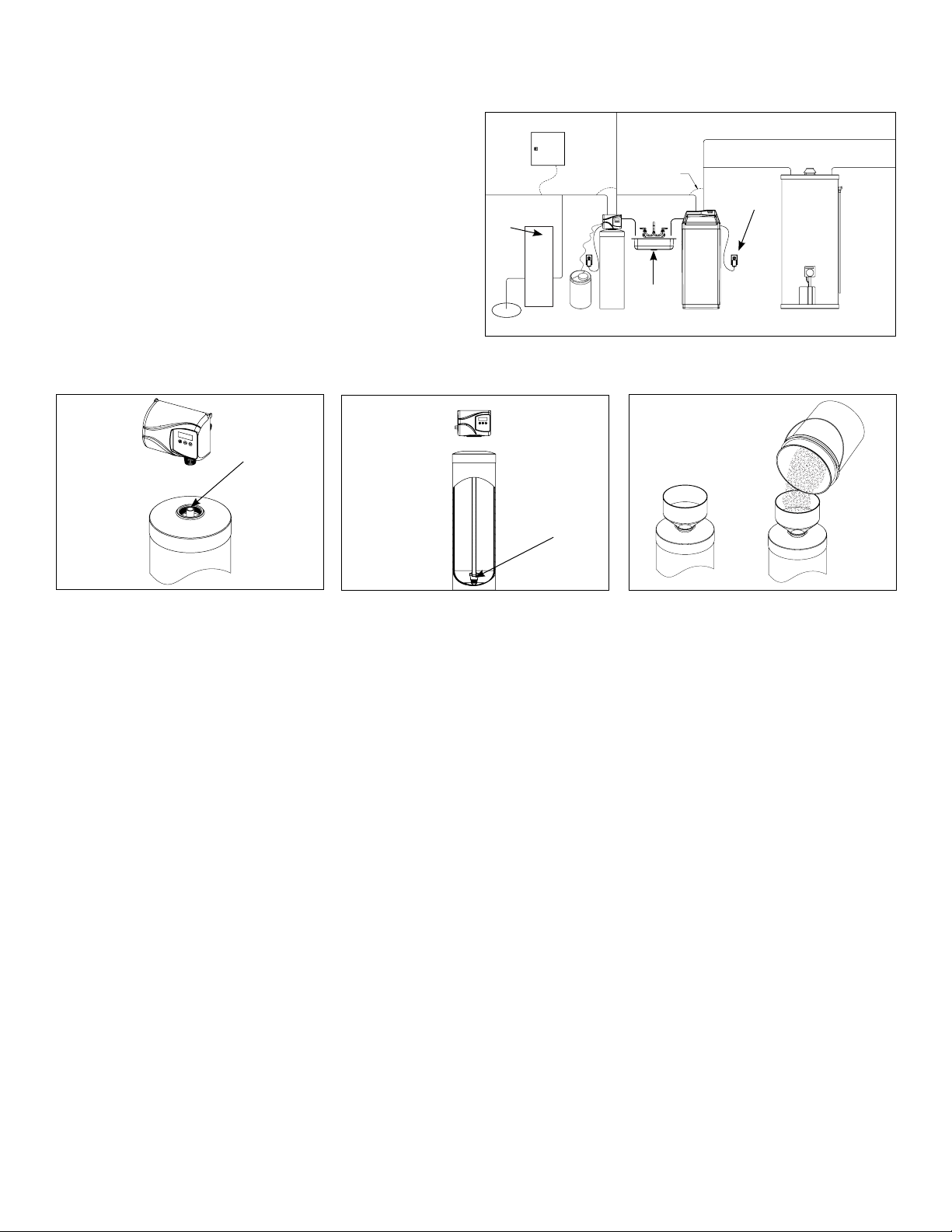
1. Determine the best location for your water filter, bearing
in mind the location of your water supply lines, drain line
and 120 volt AC electrical outlet. Subjecting the softener
to freezing or temperatures above 43°C (110°F) will void
the warranty.
2. Media Installation (When Necessary). Models including
and higher than 1.5 CF of media are shipped with separate media in pails or boxes. Models lower than 1.5 CF of
media come loaded with media and this step can be
skipped for new installation.
a
Plug
the
Riser
Tube
b
e
Electrical Panel
1
Raw
Water
To Outdoors
Pressure Tank
Pump
The riser
(distributor)
remains inside
the tank seated
in the depression
at the bottom
Iron Filter
Hard
Filtered
Water
Ground Strap
Drain Drain
Drain
e
Softener
Electrical
Outlet
Cold Soft Water
Hard Soft Water
Water Heater
a) Remove the valve from
the mineral tank.
b) Temporarily plug the open end
of the riser tube to ensure that no
resin or gravel falls down into the
distribution.
The riser (distributor) remains
inside the tank seated in the
depression at the bottom.
Plug tube with a tape.
Remove after media is loaded.
Fill support bed first (if supplied)
The media will not always spill down
inside the tank and may need to be
swept inside.
6
7
Page 8
Greensand Filter
D
C
B
d
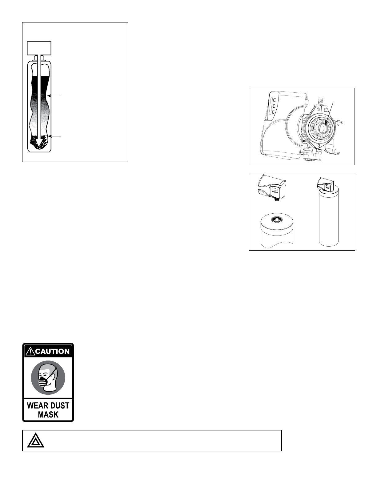
The large funnel (sold separately part
# 43000) makes filling the tank easier
and neater. (Or an empty 1 gallon or 4
liter container with the bottom cut out
makes a good funnel.)
Greensand
(Black)
Support Bed
(when supplied)
Fine, Medium and/or
Coarse Gravel
c. Fill mineral tank one quarter full of
water to protect distribution during
gravel installation.
d. Place the media into the tank in the
order indicated above. Slowly and
carefully add the gravel support
bed and the softener or filtration
media leveling each layer as it is
placed into the tank.
e. Fill support bed (if supplied) first.
During the filling process, ensure the
distributor tube stays on the bottom
of the tank, reasonably centered.
Remove the tape from the distributor once media is loaded. Whenever
possible, fill the tank outdoors to
avoid problems with dust. If filling
indoors, a dust mask should be worn.
f
O-ring
f. Unplug the riser tube, carefully posi-
tion the valve over it and turn the
valve into the threads in the fiberglass tank, tightening securely into
tank. Note: Ensure that the internal
O-ring in the valve fits securely over
the riser tube. Silicone grease (part #
92360) or other food grade lubricant
may be applied to the O-ring to
ease installation of the riser tube.
f
DO NOT use petroleum based lubricants as they will cause swelling of O-ring seals.
7
8
Page 9
The filter is now charged with resin.
g. It is recommended that the softener or filter tank now be completely filled with water (SLOWLY) to soak the resin or filtra-
tion media before startup. This will allow the media to absorb water as well as help displace any trapped air. This will
reduce the chance of backwashing resin or filter media out of the tank during the initial backwash on startup.
3. Outside faucets used to water lawns and gardens should not supply softened water. A new water line is often required to
be connected to supply hard water to the inlet of the water softener and to the outside faucets.
Cut the water line between where it enters the house and before any lines that branch off to feed the hot water heater
or other fixtures in the house and as near the desired location of the water softener as possible. Install a tee fitting on
the feed end of the cut pipe, and an elbow fitting on the other end. Install piping from the tee to the inlet of the water
softener and from the elbow to the outlet of the softener. To sever the water lines which branch off to feed any outside
faucets, cut the branch lines approximately two inches from the fitting on the main water line. Install an elbow on the
end of the pipe nearest the outside faucet and a cap on the end connected to the existing water line. Install piping from
the tee installed on the inlet line to the water softener to the elbow installed on the pipe to the outside faucet. Following
this procedure will result in all lines in the house, with the exception of the outside faucets, but including the water heater
and therefore the hot water lines, being supplied with soft water.
Installation Steps:
1
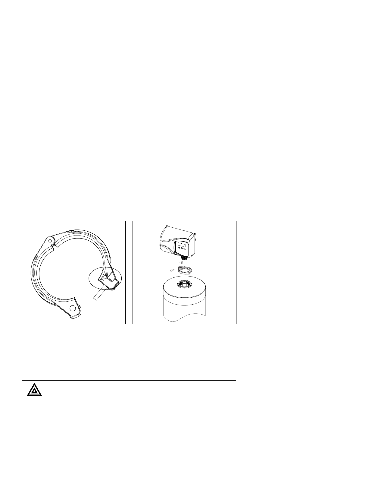
1. Clamp Ring – The clamp ring connects the control valve to the tank
and provide an easy way to disconnect tank during control valve servicing. Make sure that the clamp ring
screw is tightened.
The “Clamp Ring” should secure the valve with the top of the flange
facing up. Please note “top” on the clamp ring.
8
9
Page 10
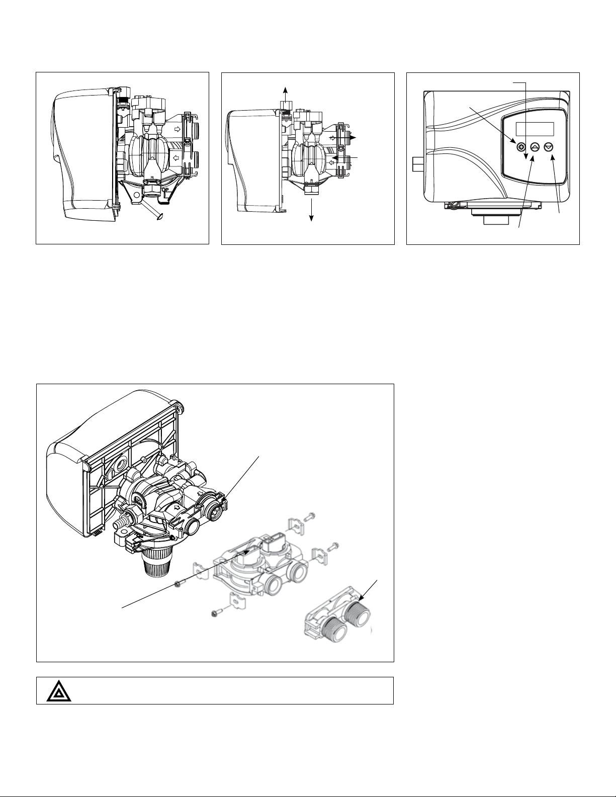
Brine Line 3/8”
Timer Controls
Extra Cycle
Button
Outlet
Inlet
4
2
2. Familiarize yourself with the location
of the inlet, outlet and drain on the
control valve. Be very careful not to
get the controls wet.
Make sure that the flow
meter is connected to the
outlet of the valve
Drain 1/2”
3
3. Familiarize yourself with the buttons
on the timer control.
4. Attach the bypass valve to the control valve (and yoke if plastic bypass
is used). Connect the inlet and outlet
of the water softener to the plumbing in the house. The control valve
must not be submitted to temperatures above 43°C (110°F). When
sweat fittings are used, to avoid
damaging the control valve, solder
the threaded copper adapters to
the copper pipe and then, using
Teflon tape, screw the assembly into
the bypass valve.
UP button
DOWN
button
Yoke
Bypass
Do not use pipe thread compound as it may attack the material
in the valve body
.
9
10
Page 11
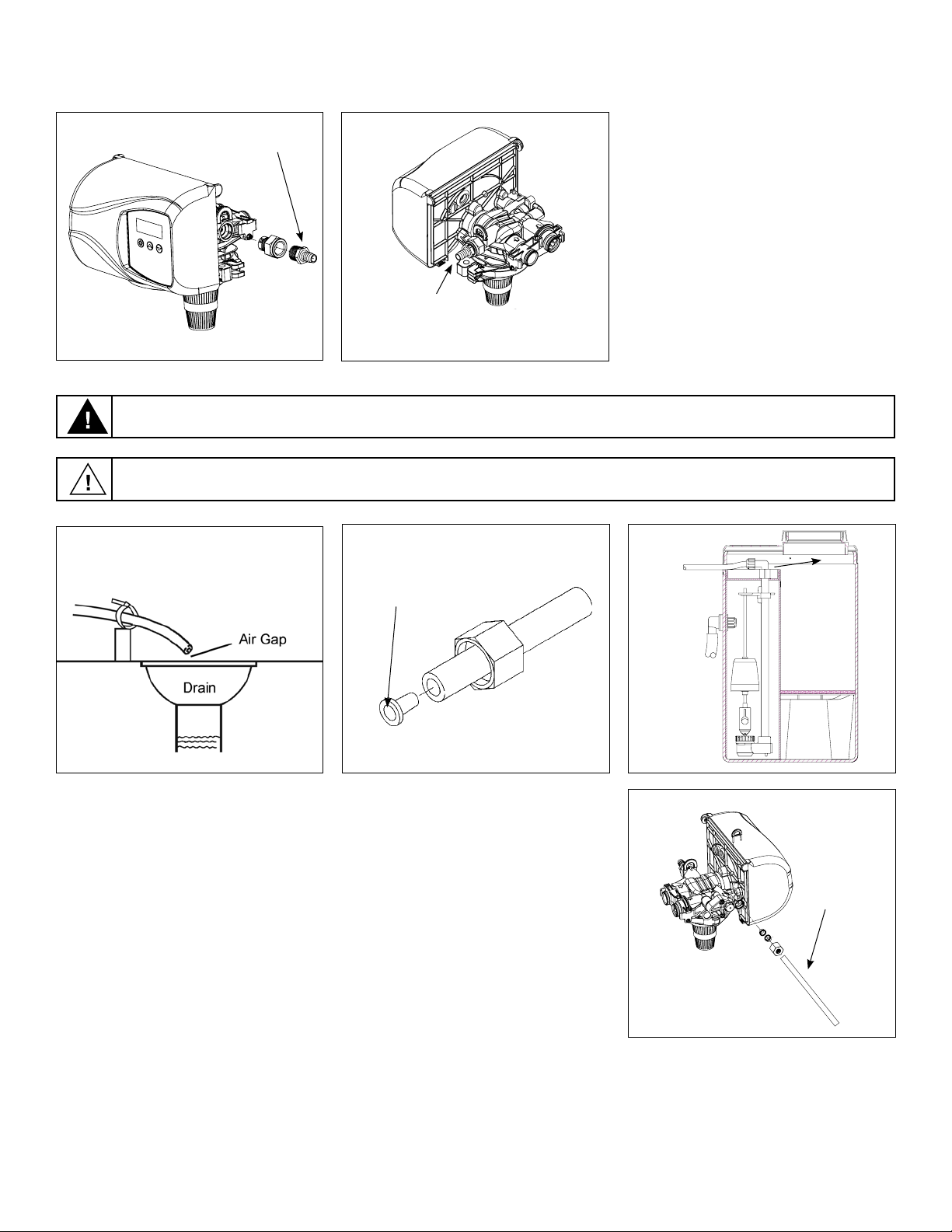
5
Waste connections or drain outlet shall be designed and constructed to provide for connection to the sanitary
waste system through an air-gap of 2 pipe diameters or 1 inch (22 mm) whichever is larger.
Never insert drain line directly into a drain, sewer line, or trap. Always allow an air gap between the drain line and
the wastewater to prevent the possibility of sewage being back-siphoned into the conditioner.
Hose Barb
5
Connect 1/2”
drain hose (not supplied)
with a hose clamp here
5. Drain Line Connection: Using teflon
tape, screw the 1/2” hose barb into
the drain port in the valve. Attach
1/2” drain hose to the hose barb and
tighten securely with a hose clamp.
Run the drain line to a floor drain or a
laundry drain. Complete any necessary plumbing.
5
6. Connect the feeder container to
the control valve with the flexible
polyethylene tubing provided. The
connection to the container is made
with the fitting nut provided (do not
overtighten).
Connect the brine line to the fitting
on the side of the valve using the nut
and ferrule. Tighten snugly. Remove
the nut from the brine line of the
valve and push the other end of the
brine tube inside it. Make sure that
the brass insert is snugged inside the
brine tubing. The brine tubing should
pass through both plastic inserts of
the black nut.
6
Tube Insert
7. Overflow Connection (Optional): In
the event of a malfunction, the brine
TANK OVERFLOW will direct “overflow”
to the drain instead of spilling on the
floor. This fitting should be installed at
the side of the cabinet or brine tank.
Attach the 5/8” hose (supplied) to the
over flow fitting on the feeder and run
the hose to the floor drain
Do not tie into drain line of control unit.
Overflow line must be a direct, separate line from overflow fitting to drain,
sewer or tub. Allow an air gap as per
drain line instructions,
6
6
Brine
Tubing
10
11
Page 12
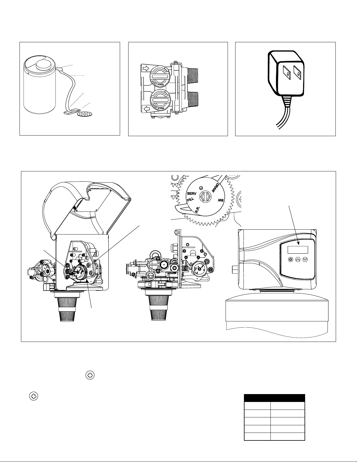
Overflow Fitting
Drain Tubing
Secure hose in place
Air Gap
Drain
7
outlet
intlet
8
9
10
Brine
Valve
8. Make sure the bypass valve is in the
service position.
Position Label
9. Plug the 24-volt transformer into a
120 VAC 60 Hz outlet.
Circuit Board Screen
Brine Cam
10. This valve has four positions: 1) Brine/
Rinse 2) Backwash 3) Rapid Rinse
and 4) Brine Refill. When the valve is
in the Service position
pressed and held for 5 seconds before it activates. Press and hold the
pic for 5 seconds to advance
the valve into the Brine Refill position. Allow to fill for 5 minutes. Make
sure there are no leaks in the top
connection to the feeder container.
must be
Advance to the Brine/Rinse position “2”. Proper draw is indicated
by upward motion of water droplets in the tube connected to the
feeder container. Allow to draw for
5 minutes to pull the air out of the
feeder container. Put control into
the service position.
11
12
The valve position during regeneration and servicing can be checked
in the circuit board screen as well
the position label on the cam.
Cycle Step Abbreviation
BD Brine Draw
BW Backwash
RR Rapid Rinse
BF Brine Refill
SV Service
Page 13
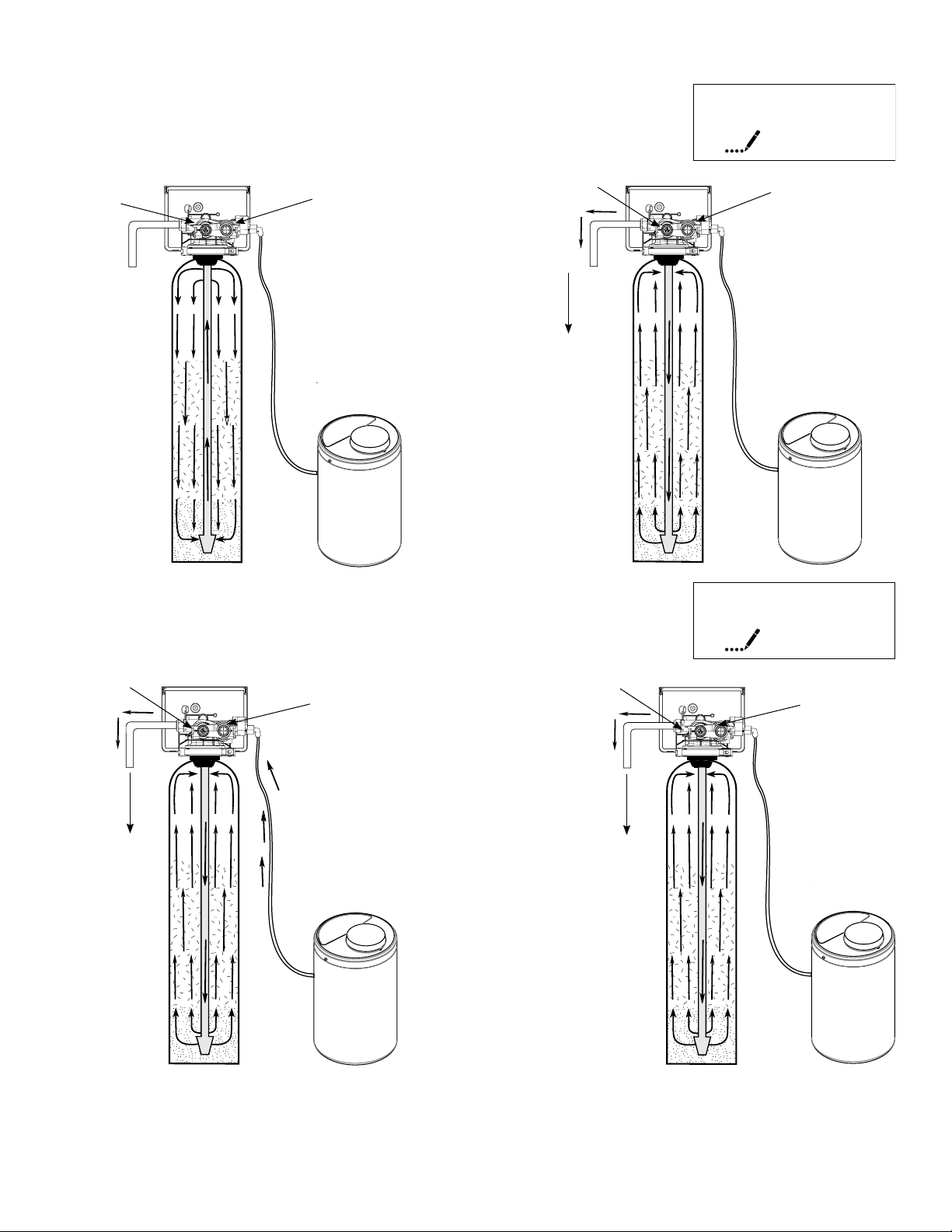
Water Conditioner Flow Diagrams
BW
Service Position Backwash Position
Untreated
Water
Treated Water
Untreated
Water
To Drain
10
Treated Water
Brine Rinse Position Slow Rinse Position
Untreated
Water
To Drain
Treated Water
Untreated
Water
To Drain
BD
60
Treated Water
11. Press the extra cycle button to advance the valve to the
“2” Backwash position. Slowly turn on the water supply
and allow the unit to backwash until the air purges out of
the tank and clears the system.
12. Press once more to advance to the “3” Rapid
Rinse position and allow water to run to drain for
2 Minutes.
12
13
Page 14
RR
10
Rapid Rinse Position Brine Refill Position
BF
12
Untreated
Water
To Drain
13. Press once more to advance to the
“4” Brine refill position.
Treated Water Treated Water
Untreated
Water
To Drain
14. Press to advance the valve from the Brine Fill position through service to the “1” position Brine/
Rinse position. Verify that water is being drawn from the tank. If not, repeat step 9.
15. Press button to advance the valve to the “2” Backwash position for 5 minutes.
16. Press to advance the valve to the “3” Rapid Rinse position.
17. Press to advance the valve to the “4” Brine Fill position for 5 minutes.
Press to advance the valve back into the service position indicated by the in upper left corner
of the display.
13
14
Page 15
19
Press and Hold
to manually regenerate
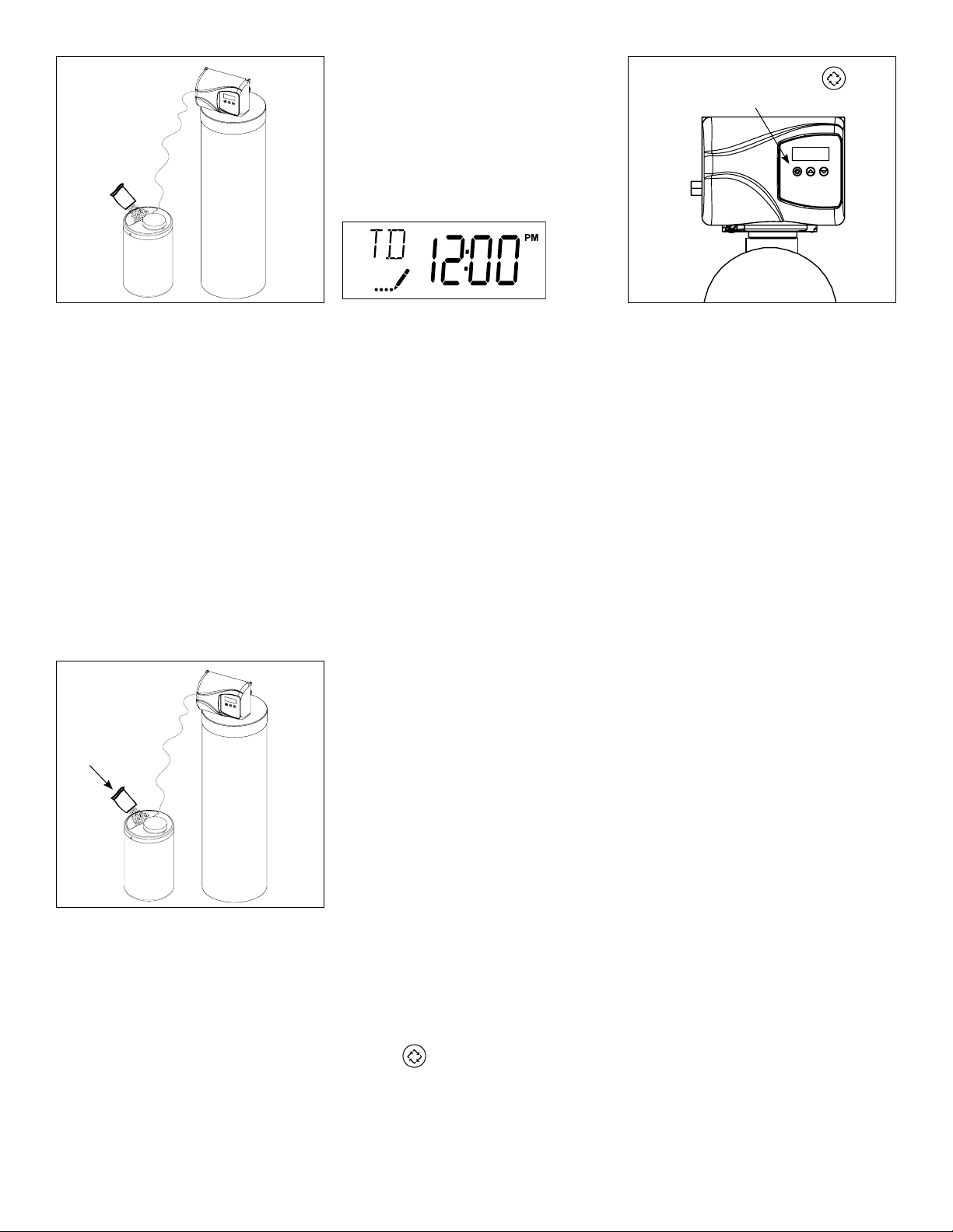
18. Cautiously pour the Potassium
Permanganate into the feeder
and replace the cover and safety
screws
19. Set time of the day in the control
valve and program the user section of the control. Refer to control
valve programming section in this
manual.
20. Manually initiate regeneration after
about one hour for the potassium
permanganate to activate the
manganese greensand by pressing
and holding extra cycle button.
Optional Sanitization Procedure: We recommend that all new water conditioners be disinfected as
part of the startup.
Sanitization
1a
Sanitization
Solution
1a. Pour entire packet of Sani-System
Liquid Concentrate – Part # 50032
(24 packets) into the brine well. If
no brine well is present, pour entire
packet into bottom of brine tank
when salt is nearly empty.
NOTE: ALL STATE AND LOCAL GOVERNMENT CODES GOVERNING INSTALLATION OF THESE DEVICES MUST BE OBSERVED.
Sanitization can also achieved by the application of chlorine in the regeneration
cycle of the conditioner. A liquid solution of 5.25% sodium hypochlorite (commonly referred to as household bleach) is recommended as a suitable disinfectant.
Use only unscented products. For every cubic foot of resin in the softener, pour
approximately two (2) tablespoons of sodium hypochlorite into the brine well
tube. The brine tank refill step of regeneration should add the correct amount of
water to the brine tank. If not, the water can be added manually now. Press and
hold the
Brine/Rinse cycle, then let the manual regeneration continue until the brine tank
is refilled again with the correct amount of water.
to begin a manual regeneration. Allow softener to complete the
14
15
Page 16
Programming Instructions
OFF
OFF
OFF
OFF
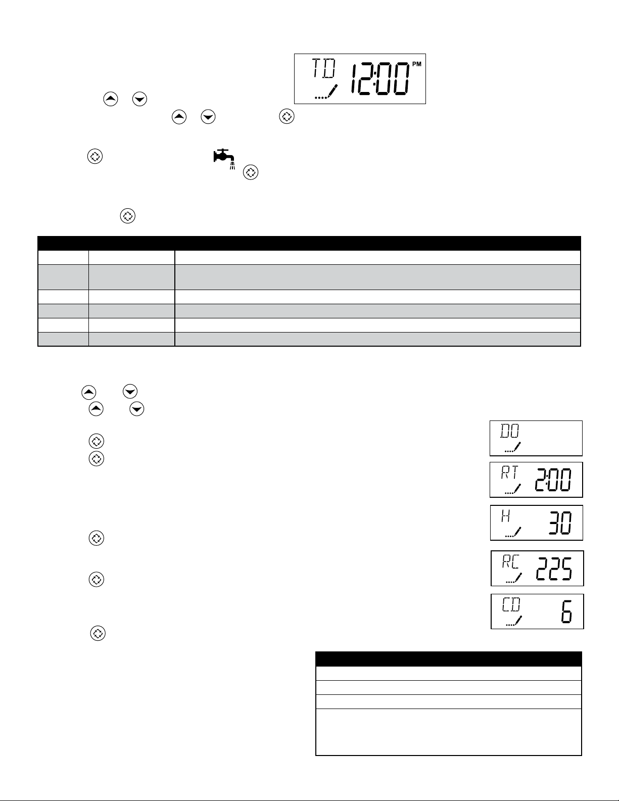
Set Time of Day
Press and hold or buttons until display reads TD
Adjust the displayed time with or buttons. Press to resume normal operation
Queuing a Regeneration
1. Press the button. The service icon will flash to indicate that a regeneration is queued.
2. To cancel a queued regeneration, press the button.
Regenerating Immediately
Press and hold the button for five seconds.
User Programming Mode Options
Abbreviation Parameter Description
DO Day Override The timer’s day override setting
THIS IS AN OPTION ONLY. PLEASE DO NOT ADJUST BEFORE CONSULTING AN AUTHORIZED DEALER.
RT Regeneration Time The time of day that the system will regenerate (meter delayed, timeclock, and day-of-week systems)
H Feed Water Hardness The hardness of the inlet water - used to calculate system capacity for metered systems
RC Reserve Capacity The fixed reserve capacity
CD Current Day The current day of week
User Programming Mode Steps
Note: Use and Down button to adjust values for parameters
1. Press the and buttons for five seconds while in service, and the time of day is NOT set to 12:01 PM.
2. Use this display to adjust the Day Override. Adjust this to OFF parameter for softeners.
3. Press the button. Use this display to adjust the Regeneration Time.
4. Press the button. Use this display to adjust the Feed Water Hardness in grains per gallon (gpg).
Hardness Compensation
1 mg/l of iron = 4 gpg
1 mg/l of manganese = 8 gpg
Maximum iron is not to exceed 1.5 mg/l total iron
Recommend the addition of a Res-up feeder when the total iron exceeds 0.5 mg/l
5. Press the button. Use this display to adjust the Fixed Reserve Capacity. This option setting is
identified by “RC” in the upper left-hand corner of the screen. 75 gallons X # of people in the
house = RC
6. Press the button. Use this display to set the Current Day of the Week. This option setting is
identified by “CD” in the upper left hand corner of the screen. This option is only available after the
Day of the Week control is set to ‘ON’ in the Master Programming. Refer to the valve manual for
details.
7. Press the button to end User Programming Mode.
In the second level mode, the control valve has been programmed as per the following main parameters related to
regeneration. For more information on master programming
manual, read control valve manual part # 54802
The valve has been pre-programmed with factory settings
as shown in the following chart:
1. Brine Rinse 60 minutes
2. Backwash 10 minutes
3. Rapid Rinse 10 minutes
4. Brine Refill 4 minutes
Regeneration Cycle Step Programming
DISF75SXT
DISF10SXT
DISF15SXT
DISF20SXT
OFF
15
16
Page 17
Diagnostic Programming Mode
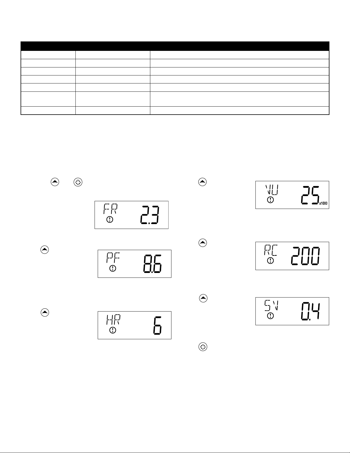
Diagnostic Programming Mode Options
Abbreviation Parameter Description
FR Flow Rate Displays the current outlet flow rate
PF Peak Flow Rate Displays the highest flow rate measured since the last regeneration
HR Hours in Service Displays the total hours that the unit has been in service
VU Volume Used Displays the total volume of water treated by the unit
RC Reserve Capacity
SV Software Version Displays the software version installed on the controller
NOTES:
Some items may not be shown depending on timer configuration.
The timer will exit Diagnostic Mode after 60 seconds if no buttons are pressed.
Press the Extra Cycle button to exit Diagnostic Mode at any time.
Diagnostic Programming Mode Steps
Displays the system’s reserve capacity calculated from the system
capacity, feed water hardness, and safety factor
1. Press the and buttons for five seconds while in
service.
2. Use this display to view
the current Flow Rate.
This option setting is
identified by “FR” in the
upper left hand corner
of the screen.
3. Press . Use this display
to view the Peak Flow
Rate since the last
regeneration cycle. This
option setting is identified
by “PF” in the upper
left hand corner of the
screen.
4. Press . Use this display
to view the Hours in
Service since the last
regeneration cycle. This
option setting is identified
by “HR” in the upper
left hand corner of the
screen.
5. Press . Use this display
to view the Volume
Used since the last
regeneration cycle. This
option setting is identified
by “VU” in the upper
left hand corner of the
screen.
6. Press . Use this display
to view the Reserve
Capacity. This option
setting is identified by
“RC” in the upper left
hand corner of the
screen.
7. Press . Use this display
to view the Software
Version. This option setting
is identified by “SV” in the
upper left hand corner of
the screen.
8. Press to end Diagnostic Programming Mode.
16
17
Page 18

Controller Behavior
Control Operation During Programming
The control will only enter the Program Mode with the valve in Service. While in the Program Mode, the control will
continue to operate normally, monitoring water usage and keeping all displays up to date. Control programming is stored
in memory permanently, eliminating the need for battery back-up power.
Meter Immediate Control
A meter immediate control measures water usage and regenerates the system as soon as the calculated system capacity
is depleted. The control calculates the system capacity by dividing the unit capacity (typically expressed in grains/unit
volume) by the feedwater hardness and subtracting the reserve. Meter Immediate systems generally do not use a reserve
volume. However, in twin tank systems with soft-water regeneration, the reserve capacity should be set to the volume
of water used during regeneration to prevent hard water break-through. A Meter Immediate control will also start a
regeneration cycle at the programmed regeneration time if a number of days equal to the regeneration day override
pass before water usage depletes the calculated system capacity.
Meter Delayed Control
A Meter Delayed Control measures water usage and regenerates the system at the programmed regeneration time after
the calculated system capacity is depleted. As with Meter Immediate systems, the control calculates the system capacity
by dividing the unit capacity by the feedwater hardness and subtracting the reserve. The reserve should be set to insure
that the system delivers treated water between the time the system capacity is depleted and the actual regeneration
time. A Meter Delayed control will also start a regeneration cycle at the programmed regeneration time if a number of
days equal to the regeneration day override pass before water usage depletes the calculated system capacity.
Time Clock Delayed Control
A Time Clock Delayed Control regenerates the system on a timed interval. The control will initiate a regeneration cycle at
the programmed regeneration time when the number of days since the last regeneration equals the regeneration day
override value.
Day of the Week Control
This control regenerates the system on a weekly schedule. The schedule is defined in Master Programming by setting
each day to either “off” or “on.” The control will initiates a regeneration cycle on days that have been set to “on” at the
specified regeneration time.
Control Operation During a Power Failure
The SXT includes integral power backup. In the event of power failure, the control shifts into a power-saving mode. The
control stops monitoring water usage, and the display and motor shut down, but it continues to keep track of the time and
day for a minimum of 48 hours.
The system configuration settings are stored in a non-volatile memory and are stored indefinitely with or without line power.
The Time of Day flashes when there has been a power failure. Press any button to stop the Time of Day from flashing.
If power fails while the unit is in regeneration, the control will save the current valve position before it shuts down. When
power is restored, the control will resume the regeneration cycle from the point where power failed. Note that if power fails
during a regeneration cycle, the valve will remain in it’s current position until power is restored. The valve system should
include all required safety components to prevent overflows resulting from a power failure during regeneration.
The control will not start a new regeneration cycle without line power. If the valve misses a scheduled regeneration due to
a power failure, it will queue a regeneration. Once power is restored, the control will initiate a regeneration cycle the next
time that the Time of Day equals the programmed regeneration time. Typically, this means that the valve will regenerate
one day after it was originally scheduled. If the treated water output is important and power interruptions are expected,
the system should be setup with a sufficient reserve capacity to compensate for regeneration delays.
17
7
Page 19
During Regeneration
Automatic Bypass
The regeneration cycle lasts approximately 2 hours, after which soft water service will be restored. During regeneration, hard
water is automatically bypassed for use in the household. Hot water should be used as little as possible during this time to
prevent hard water from filling the water heater.
IMPORTANT: This is why the automatic regeneration is set for sometime during the night and manual regenerations should be
performed when little or no water will be used in the household.
New Sounds
You may notice new sounds as your water softener operates. The regeneration cycle lasts approximately 2-1/2 hours. During
this time, you may hear water running intermittently to the drain.
Water Bypass
Figure 5A
Figure 5B
Outlet
Inlet
Outlet
Inlet
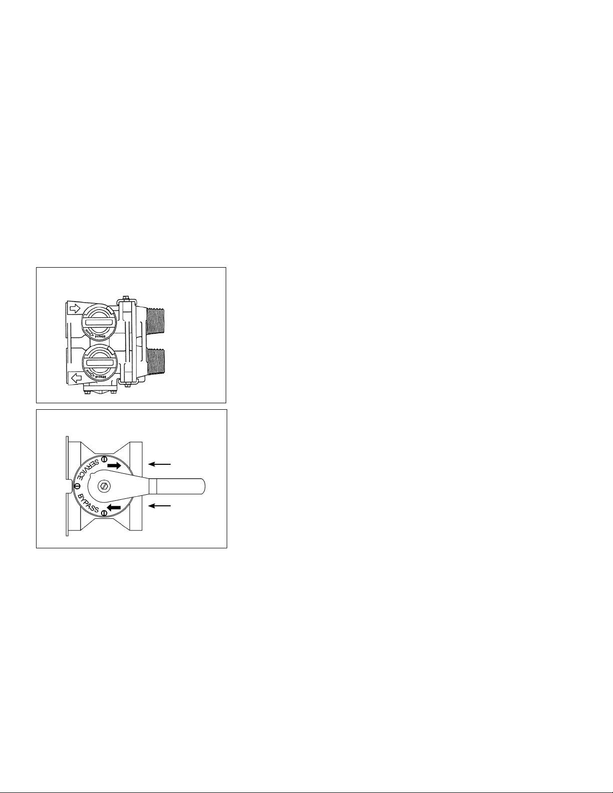
Manual Bypass (Figure 5A)
In case of an emergency such as an overflowing brine tank, you can isolate
your water softener from the water supply using the bypass valve located
at the back of the control. In normal operation the bypass is open with the
ON/OFF knobs in line with the INLET and OUTLET pipes. To isolate the softener,
simply rotate the knobs clockwise (as indicated by the word BYPASS and arrow) until they lock. You can use your water related fixtures and appliances
as the water supply is bypassing the softener. However, the water you use will
be hard. To resume soft water service, open the bypass valve by rotating the
knobs counter-clockwise.
Stainless Steel Bypass (Figure 5B)
In normal operation the bypass lever is aligned with the inlet/outlet with the
pointer on SERVICE. To isolate the softener or filter, rotate lever counter clockwise until it stops and pointer indicates unit is in bypass.
You can use your water related fixtures and appliances as the water supply is
bypassing the softener and filter. However, the water you use will be hard or
untreated. To resume treated water service, open the bypass valve by reversing the rotation of the lever.
18
Page 20

To determine the frequency of regeneration, use this procedure:
Setting the Frequency of Automatic Regeneration (SXT Models)
Please enter the ppm of compensated iron per gallon of water to be removed. See Step #4 of “User Programming.”
The SXT valve will automatically calculate the number of gallons of water to be treated by the iron filter between
regenerations.
Iron Content in the Feed Water:
ppm of capacity between regenerations (see Specifications - Page 1)
÷ ppm of iron in the water sample*
= number of gallons supplied between regenerations
- reserve capacity (number of people x 75 gallons)
Example - Using 5600 SXTM-948IF + 1 Feeder
6000 ppm between regenerations
÷ 8 ppm of compensated iron [To be entered by the user]
= 750 gallons between regenerations [See step #5 of “User Programming”]
- 375 gallons reserve capacity (5 people x 75 gallons)
= 375 GALLONS - BETWEEN REGENERATIONS [Calculated by valve]
* 1 ppm of manganese = 2 ppm of iron; 1 ppm of hydrogen sulfide = 3 ppm of iron
Days:
Total amount of iron to be removed between regenerations -
÷ ppm of iron to be removed per day
= NUMBER OF DAYS BETWEEN REGENERATIONS
Example:
5 people in the household
x 75 gallons of filtered water per person
= 375 gallons of filtered per day
x 8 ppm of compensated iron
= 3,000 PPM OF IRON TO BE REMOVED PER DAY
Using 5600 SXTM-948IF + 1 Feeder
6,000 ppm capacity
÷ 3,000 ppm to be removed per day
= 2** DAYS BETWEEN REGENERATIONS
**Maximum number of days between regenerartions should be 12.
19
20
Page 21

Manual Regeneration Cycle
If you run out of filtered water because of inadequate regeneration frequency, inadequate reserve capacity, power
failure or unusually high water usage, you can initiate a manual regeneration simply by pressing the extra cycle button.
The filter will now automatically complete a regeneration cycle and return to service. If possible, avoid water use during
the regeneration cycle.
Once you have set your filter you may experience frequent loss of water pressure, you may have to increase the
frequency of regeneration by decreasing the number of gallons between regeneration.
Potassium Permanganate Feeder
The potassium permanganate feeder assembly incorporates a non-pressurized storage tank and innovative new grid
design along with a dependable float valve.
The attractive 10” x 16” black tank is made of touch blow-molded high density polyethylene. It has a potassium
permanganate capacity of 30 lbs. and a liquid capacity of 5 gallons.
The black injection molded cover is securely fastened with three stainless steel safety screws to prevent access by children
and pets. Also, the potassium chemical tank should be placed where it is free from possible upset or access by children or
pets.
Chemical warning label and drain caution label are affixed to unit.
The unique polypropylene grid pad refuses to allow even the finest grade of undissolved potassium permanganate to
pass through the grid. This permits efficient use of our assembly with all grades of potassium permanganate. Standard grid
platform height is 6”. Additional heights are available - consult factory.
202221
21
Page 22
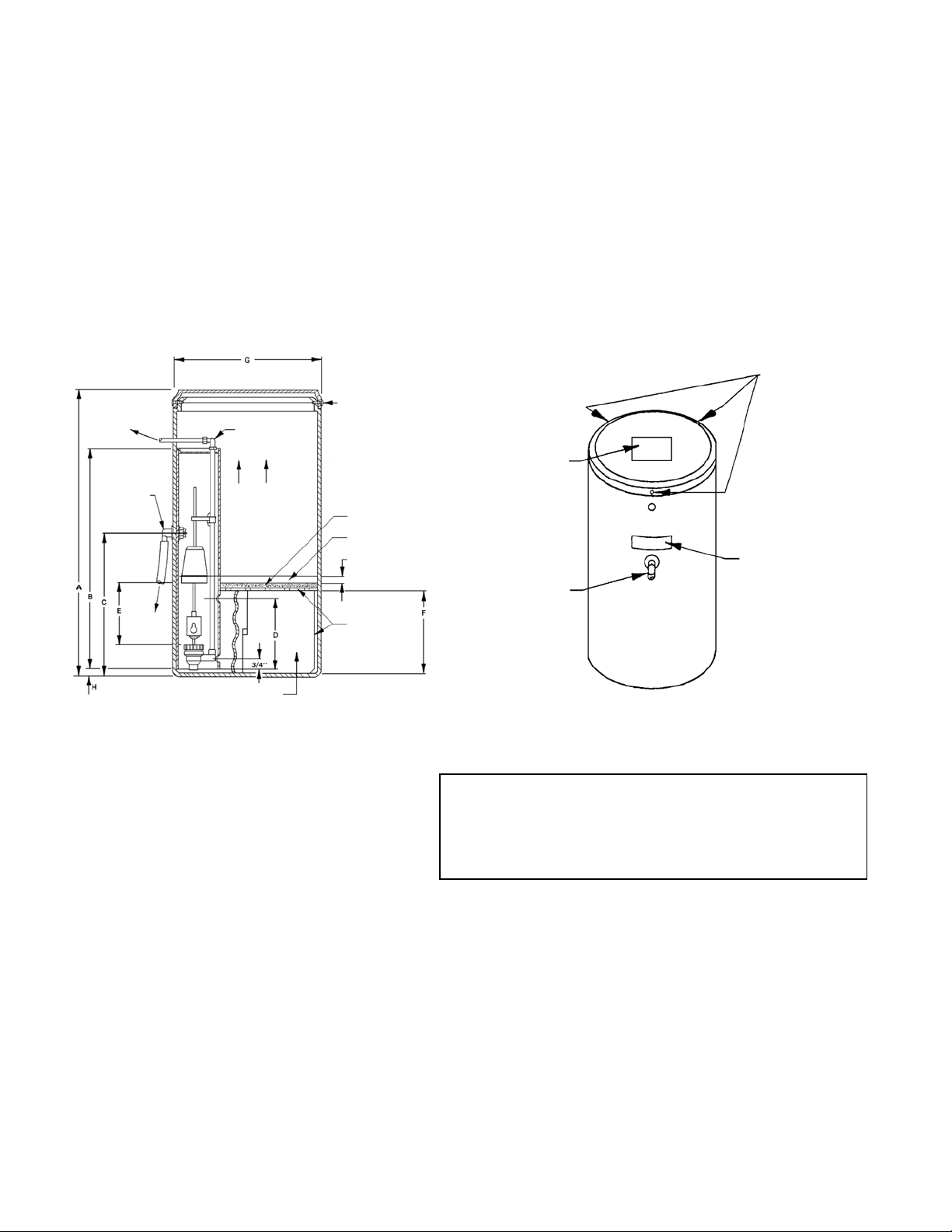
The unit is shipped fully tested and assembled and weighs approximately 7 lbs. The feeder assembly includes:
10” x 16 “ black tank Black injection molded cover
3 Stainless steel safety screws Grid with polypropylene grid pad
4” Well and cap Float valve
15 ft of 5/8” x 1/2” poly drain tubing* Chemical warning label
Drain caution label 4 ft of 1/4” or 3/8” suction tubing
1/4” PVC riser pipe 1/2” Overflow fitting
1/4” or 3/8” poly tube elbow
The potassium storage tank placement should be such to permit the installation of the overflow line to a permanent drain
facility.
Location of
Three Safety
Screws
Location of
Drain Label
Valve
Overflow
To
2 Piece
Approved
To
Drain
Poly Tube
Elbow
Dry Potassium
Permanganate
Storage
Safety Screws
Polypropylene
Grid Pad
Wet Permanganate
Solution
1_” Min.
Polyethylene
Grid Plate &
Supports
Location of
Warning
Label
To Approved
Drain
Dimensions - Inches
A = 16-1/2” E = See Table
B = 14-1/2” F = 5-3/4” (2 oz. to 4 oz.)
C = 10-1/2” 7-5/8” (6 oz.)
D = 5-1/4” G = 10-1/2”
H = 1/8”
Oz. Of Potassium Gallons of Float Riser Pipe
Permanganate Solution Setting Length
2 3/4 2-1/2 11
4 1 4 12-1/2
6 1-1/2 5-5/8 12-1/2
Correct water temperature is important for obtaining
properly dissolved potassium permanganate.
Tables based on permanganate solubility of 4 oz/gal at 50°F or 8 oz/gal at 72°F.
Float setting is based on distance between brine valve top body nut and the bottom of the float with the valve in the
closed (float up) position.
All dimensions nearest 1/4 inch.
Iron and Manganese Removal
A recommended dose of 2 oz. to 6 oz. of potassium permanganate per cubic foot of manganese greensand is
suggested for regeneration. Correct water temperature is important in obtaining proper dissolving of potassium
permanganate. At 50°F (10°C), 4 oz. of potassium permanganate can dissolve in one gallon of water. At room
temperature 72°F (22°C), 8 oz. will dissolve in one gallon of water.
Page 23
Maintenance Instructions
Care of Your Filter
To retain the attractive appearance of your new water filter, clean occasionally with a mild soap solution. Do not use
abrasive cleaners, ammonia or solvents. Never subject your softener to freezing or to temperatures above 43°C (110°F).
Servicing Components.
• Theinjectorassemblyshouldbecleanedorreplacedeveryyeardependingontheinletwaterqualityandwaterusage.
• Thesealsandspacercartridgeshouldbeinspected/cleanedorreplacedeveryyeardependingontheinletwater
quality and water usage.
Please refer to the servicing section of this manual for step by step procedure.
Not following the above will void all warranty on the control valve.
Servicing 6200 Valve
Before Servicing
1. Turn off water supply to conditioner :
a. If the conditioner installation has a 3 valve bypass system first open the valve in the bypass line, then close the valves at
the conditioner inlet & outlet.
b. If the conditioner has an integral bypass valve, put it in the bypass position.
c. If there is only a shut-off valve near the conditioner inlet, close it.
2. Relieve water pressure in the conditioner by stepping the control into the backwash position momentarily. Return the
control to the In Service position. (Refer to programming instructions)
3. Unplug Electrical Cord from outlet.
4. Disconnect brine tube and drain line connections.
WARNING! ELECTRICAL SHOCK HAZARD! UNPLUG THE UNIT BEFORE REMOVING THE COVER OR ACCESSING ANY
INTERNAL CONTROL PARTS.
CAUTION! Disassembly while under pressure can result in flooding. Always follow these steps prior
to servicing the valve.
10
22
Page 24
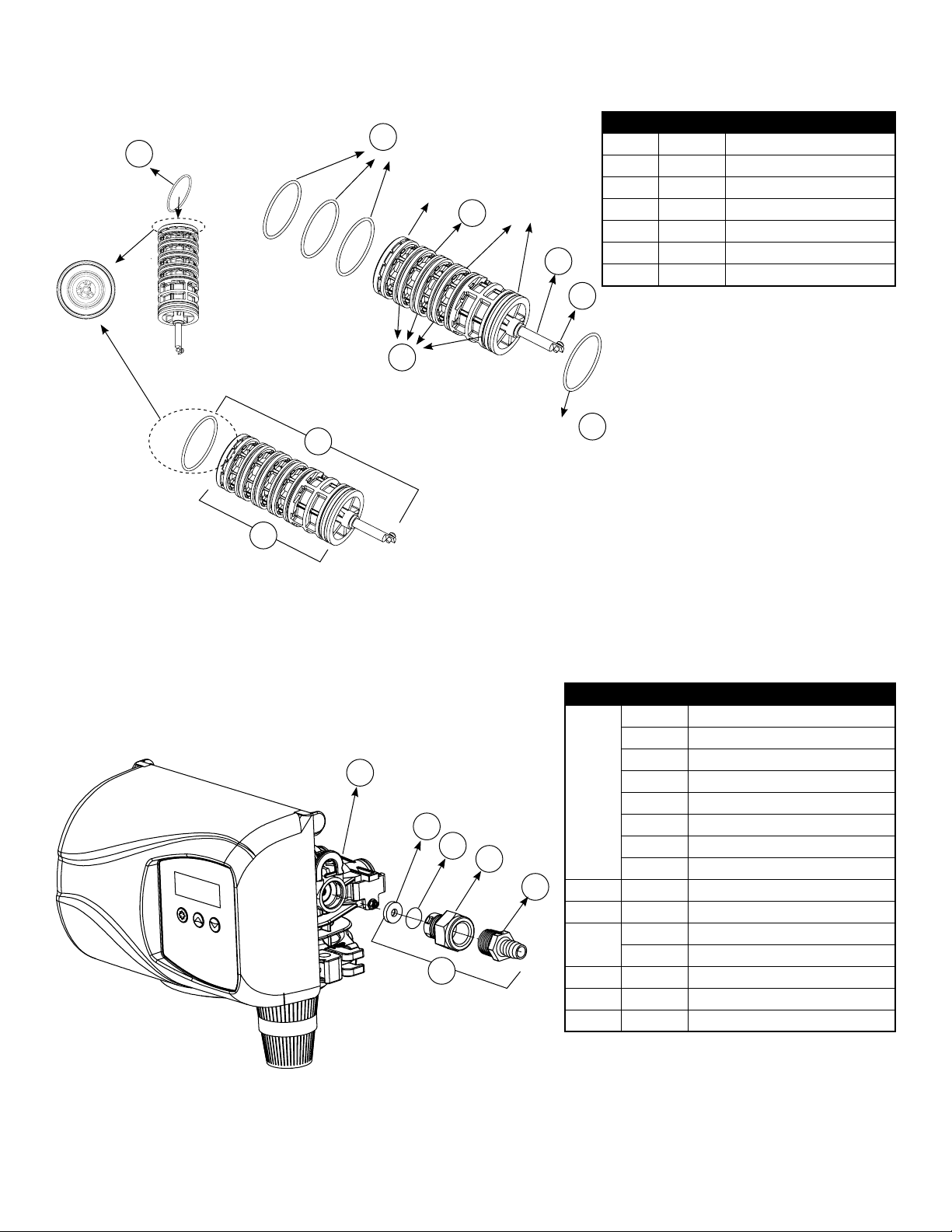
6200 Service Kits – Piston and Cartridge Assembly
B
4
3
2
1
5
D
C
6
REVISIONS
DATE
APP'D
DESCRIPTION
REV.
ECN
ZONE
O-Ring
98
99
O-Ring
O-Ring
7
97
97
Blank
100
Blank
O-Ring
101
Dwg # Part # Part Description
7 61799-01 Cartridge Assembly with Piston
76 11335 Screw, 4-40X3/16
97 16394 O-Ring, 029
98 13287 O-Ring, 123
99 61799 Seal and Spacer Cartridge
100 42920 Piston
101 19984 Piston Rod
76
97
6200 Service Kits – Drain Line Flow Control Kits
19
61
62
63
88
89
Dwg # Part # Part Description
12085 Washer, Flow, 1.2 GPM
12086 Washer, Flow, 1.50 GPM
12087 Washer, Flow, 2.0 GPM
61
12088 Washer, Flow, 2.4 GPM
12089 Washer, Flow, 3.0 GPM
12090 Washer, Flow, 3.5 GPM
12091 Washer, Flow, 4.0 GPM
12092 Washer, Flow, 5.0 GPM
62 11183 O-Ring, 017
63 11385-01 Adapter, Fitting, DLFC
88
13308 Hose Barb, Straight, DLFC,1/2"
12388 Hose Barb, 90 Deg, DLFC,1/2"
89 60705-XX DLFC Assembly, XX GPM For < 7 GPM
60706-XX DLFC Assembly, XX GPM For > 7 GPM
19 18312 Retainer, Drain
23
Page 25
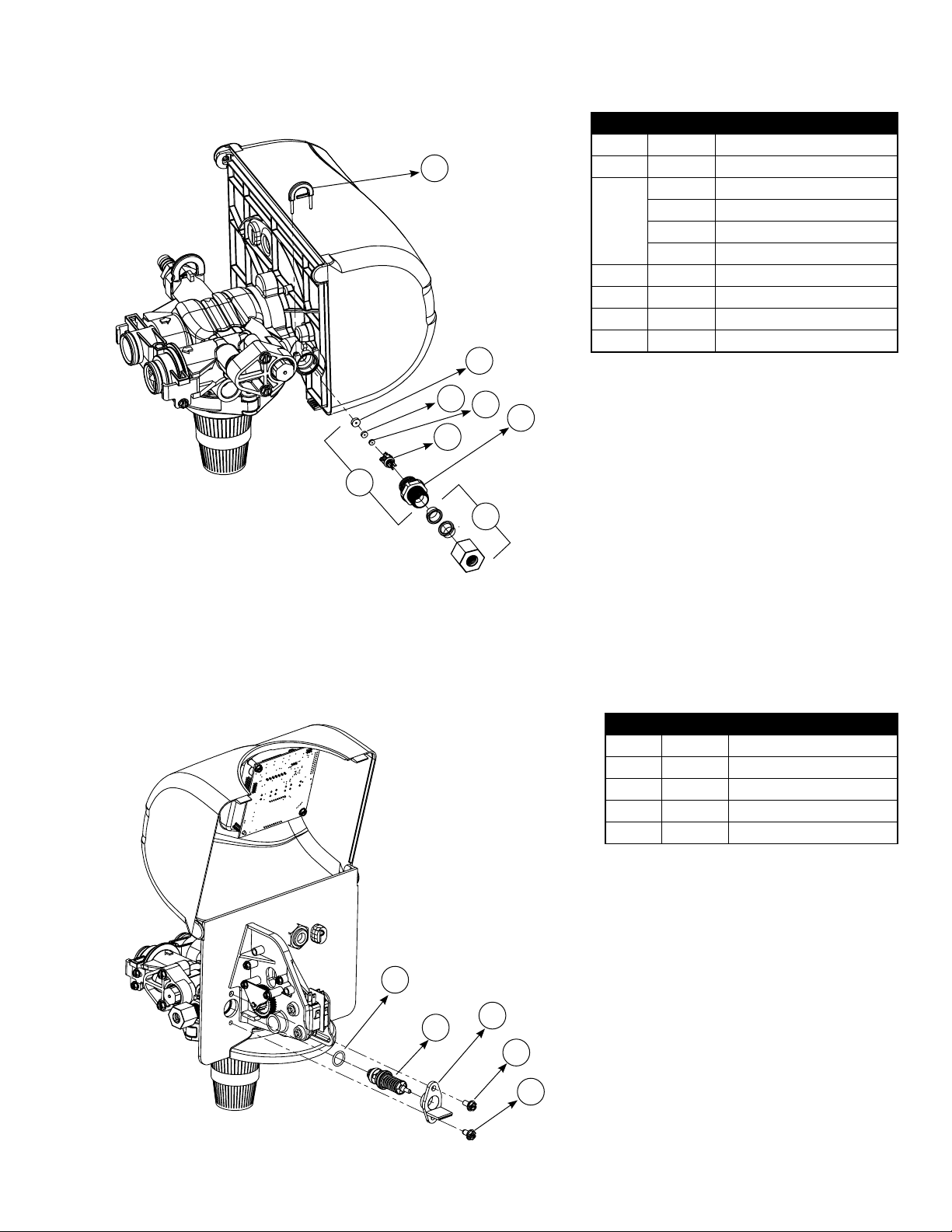
6200 Service Kits – Brine Line Flow Control Kits
18
17
12
68
16
15
95
20
Dwg # Part # Part Description
17 13302 O-Ring, 014
12 10141 O-Ring, 010
17307 Washer, Flow, 0.125 GPM
68
15 19334 Retainer, Flow Washer, BLFC
16 19335 Fitting, BLFC,3/8"
20 19625 Nut, Assembly, 3/8" Plastic
95 60422-XX BLFC Assembly, Specify XX=GPM
12094 Washer, Flow, 0.25 GPM
12095 Washer, Flow, 0.5 GPM
12097 Washer, Flow, 1.0 GPM
6200 Service Kits – Brine Valve
17
93
Dwg # Part # Part Description
17 13302 O-Ring, 014
93 60032 Brine Valve Assembly
52 40055-06 Bracket, Plastic
53 15137 Screw, Hex Washer Head
60 40134 Screw, Self Tap
52
53
60
24
Page 26
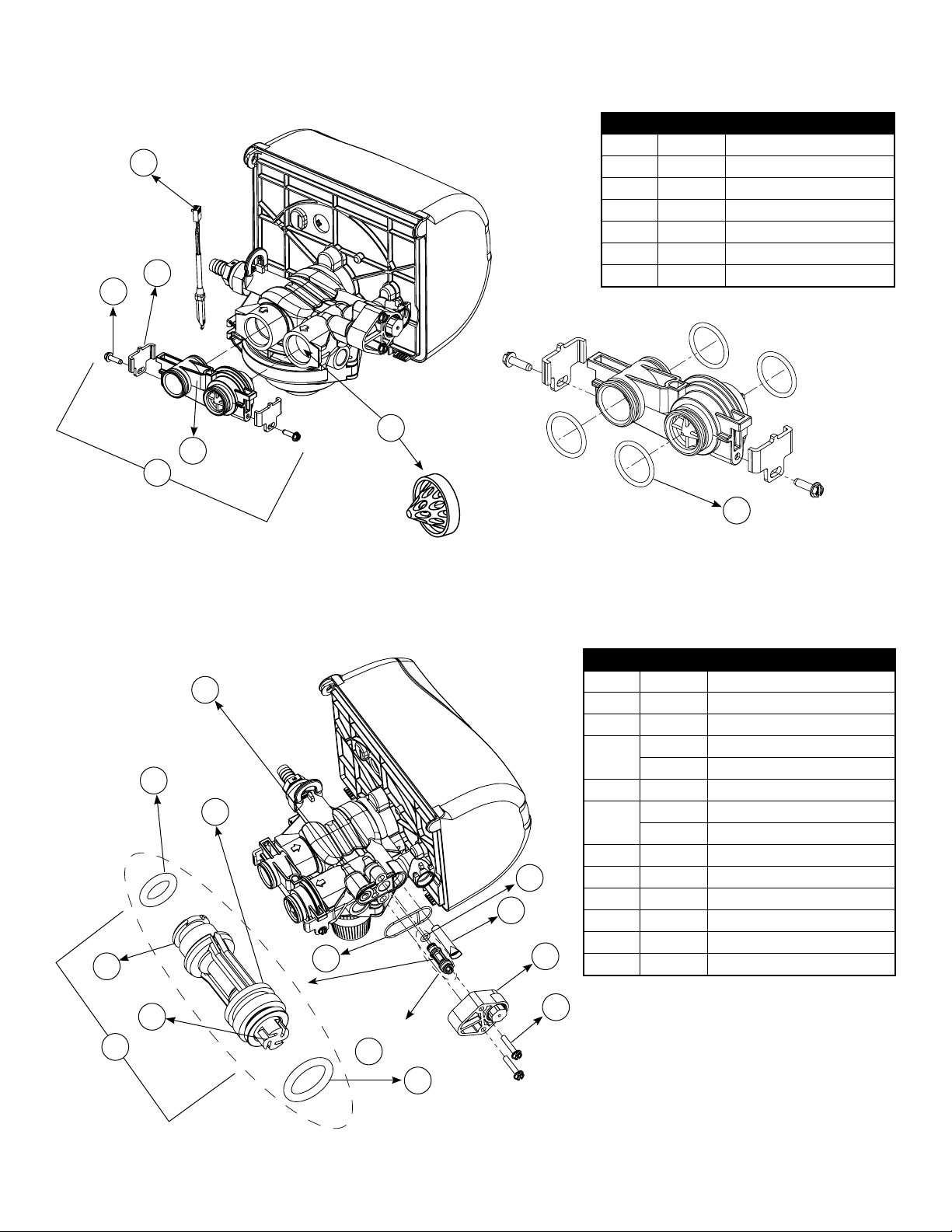
6200 Service Kits – Flow Meter
84
22
24
23
94
Dwg # Part # Part Description
84 19791-01 Cable, Meter
22 19569 Clip, Flow Meter
24 13314 Screw, Slot Hex, 8-18 X0.6
23 19797 Meter, Assy,3 /4" Dual Port
105 13305 O-Ring, -119
21 14613 Flow Straightener
94 60626 Meter Only, Electronic Turbine
21
105
6200 Service Kits – Injector Assembly
91
12
66
65
67
90
14
Replace with
for filter valve
91
56
64
58
29
Dwg # Part # Part Description
91 18276-01 Plug, Injector, Assembly
64 040095 Flow Dispersor
56 40058 Screen, Injector
40079-20 Cap, Injector, Regulated, Softener
58
29 18262 Screw, #10-24 X 1
14
66 18275-X Throat, Injector, Specify Size X
65 18274-X Nozzle, Injector, Specify Size X
12 10141 O-Ring, -010
67 18273 Generator, Vortex
13 13771 O-Ring, -012
90 61514-XX Injector Assembly, Specify Size XX
18277 Cap, Injector Filter
040064 Seal, Injector, Softener
18301 Seal, Injector, Filter
13
25
Page 27

6200 Service Kits – Circuit Board
82
37
Dwg # Part # Part Description
82 19474-01 Harness, Power, SXT
84 19791-01 Cable Meter
36 42766-02 Circuit Board, SXT
37 17020 Screw
36
84
6200 Service Kits – Other Parts
37
34
85
24
51
Dwg # Part # Part Description
37 17020 Screw, Stl Hex, 6-20 X 3/8
51 040050 Screw, Hex Washer
34 42919 Cam, Brine
85
24 13314 Screw, Slot, Hex, 8-18 X 0.60
87 18280 Collector, Top, 1"
48 19619 Bracket, Idler
47 43298 Gear Idler
42 10218 Switch, Micro
42
47
43107 Label, Cam Position, Softener
43121 Label, Cam Position, Filter
87
48
26
Page 28
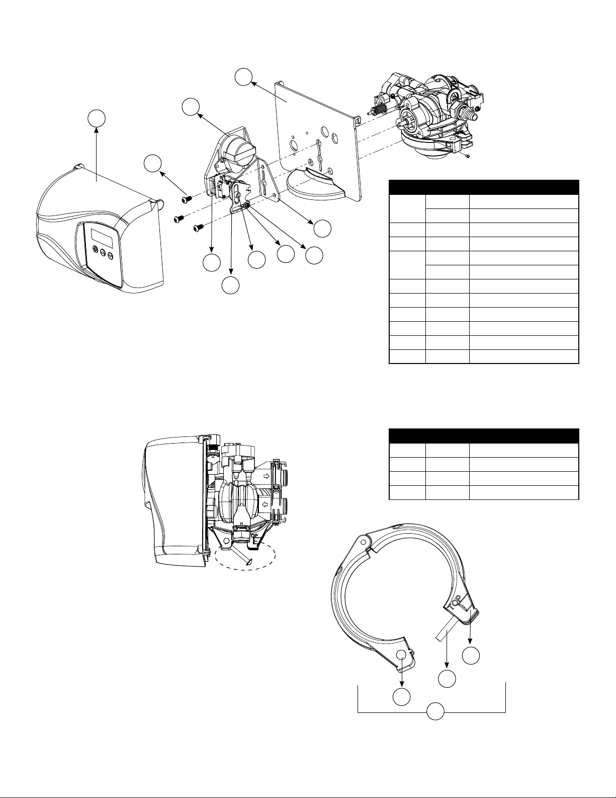
6200 Service Kits – Other Parts Continued
35
49
40
54
55
43
31
32
37
41
Dwg # Part # Part Description
43052-01 Cover, Black
40
43052-02 Cover, Cream
54 10231 Screw, Slot Hex, 1/4-20 X 1/2
49 19597 Motor, 24V, 50/60 Hz
43053-01 Backplate, Black
35
43053-02 Backplate, Cream
41 19 581 Bracket, Drive
43 10302 Insulator, Limit Switch
32 019688 Link, Piston Rod
31 019493 Shaft, Drive
55 13363 Washer
37 17020 Screw, Hex, 6-20 X 3/8
Dwg # Part # Part Description
28 19998 Shaft, Drive
27 40057 Screw, Hex Washer Head
26 40254 Clamp, Ring
92 60503 Clamp Ring Assembly
26
27
28
92
27
Page 29
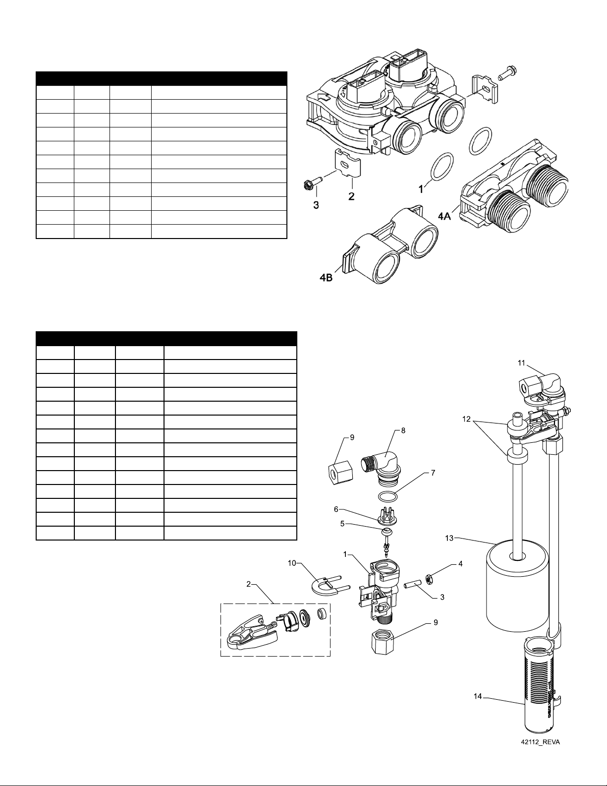
Bypass Valve Assembly & Yokes (Plastic)
Item No. Quantity Part No. Description
1 2 13305 O-ring, -119
2 2 13255 Clip, Mounting
3 2 13 314 Screw, Hex Washer Head, 8-18 x 5/8
4A 1 18706 Yoke, Plastic, 1” NPT
18706-02 Yoke, Plastic, 3/4” NPT
4B 1 13708 Yoke, Brass, 3/4” NPT
13708NP Yoke, 3/4” NPT Nickel Plated
13398 Yoke, Brass, 1” NPT
13398NP Yoke, 1” NPT Nickel Plated
40636 Yoke, 1 1/4” NPT
40636-49 Yoke, 1 1/4” Sweat
2310 Safety Brine Valve
Item No. Quantity Part No. Description
1 1 19645 Body, Safety Brine Valve, 2310
2 1 19803 Safety Brine Valve Assembly
3 1 19804 Screw, Socket Hd, Set, 10-24 X .75
4 1 19805 Poppet Assembly, SBV w/O-ring
5 1 19652-01 3RSSHW $VV\, 6%9 Z/2-ULQJ
6 1 19649 Flow Dispenser
7 1 11183 O-ring, -017
8 1 19647 Elbow, Safety Brine Valve
9 2 19625 Nut Assembly, 3/8” Plastic
10 1 18312 Retainer, Drain
11 1 60014 Safety Brine Valve Assembly, 2310
12 2 10150 Grommet, .30 Diameter
13 1 60068-30 Float Assembly, 2310, w/30” Rod
14 1 60002-34 Air Check, #500, 34” Long
28
Page 30
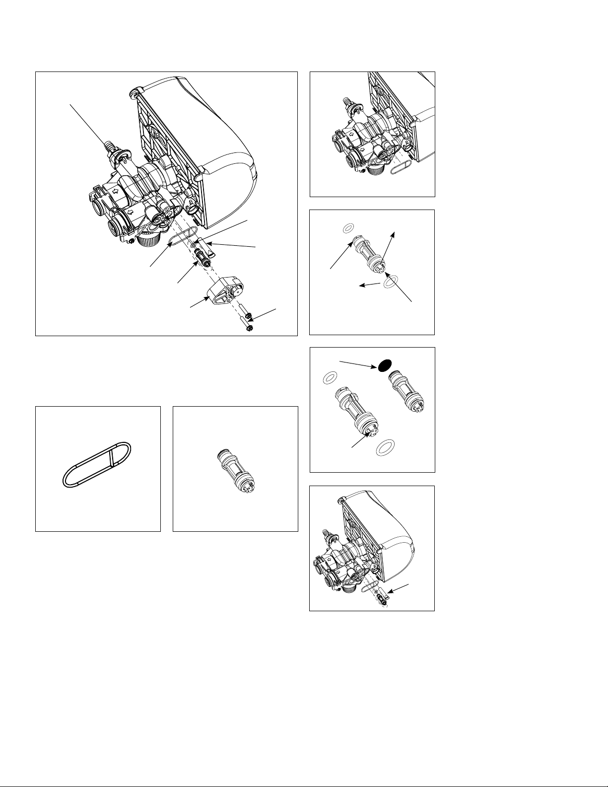
Servicing 6200 SXT Upflow Control Valve – Replacing Injectors and Screen
4. Apply silicone lubricant
Valve Body
to the gasket and install
around oval extension on
injector cap.
Gasket
Injector
Assembly
Injector
Cap
1. Unscrew the injector cap from the valve body
Disperser
Screen
Screw
Two
O-Rings
Disperser
Vortex
Generator
Disperser
Vortex
Generator
5. Apply silicone lubricant to
two new o-rings and install
over 2 bosses of the new
injector assembly.
6. Apply silicone grease to
the dispersor and press
it on the surface of the
injector assembly.
7. Screw in new injector
throat and nozzle (make
sure that vortex generator
is installed in the injector
body), be sure they are
seated tightly.
8. Install a new screen.
9. Tighten injector cap on
to the valve body.
2. Discard gasket.
3. Remove injector assembly from the valve body
and discard it.
30
29
Screen
Page 31
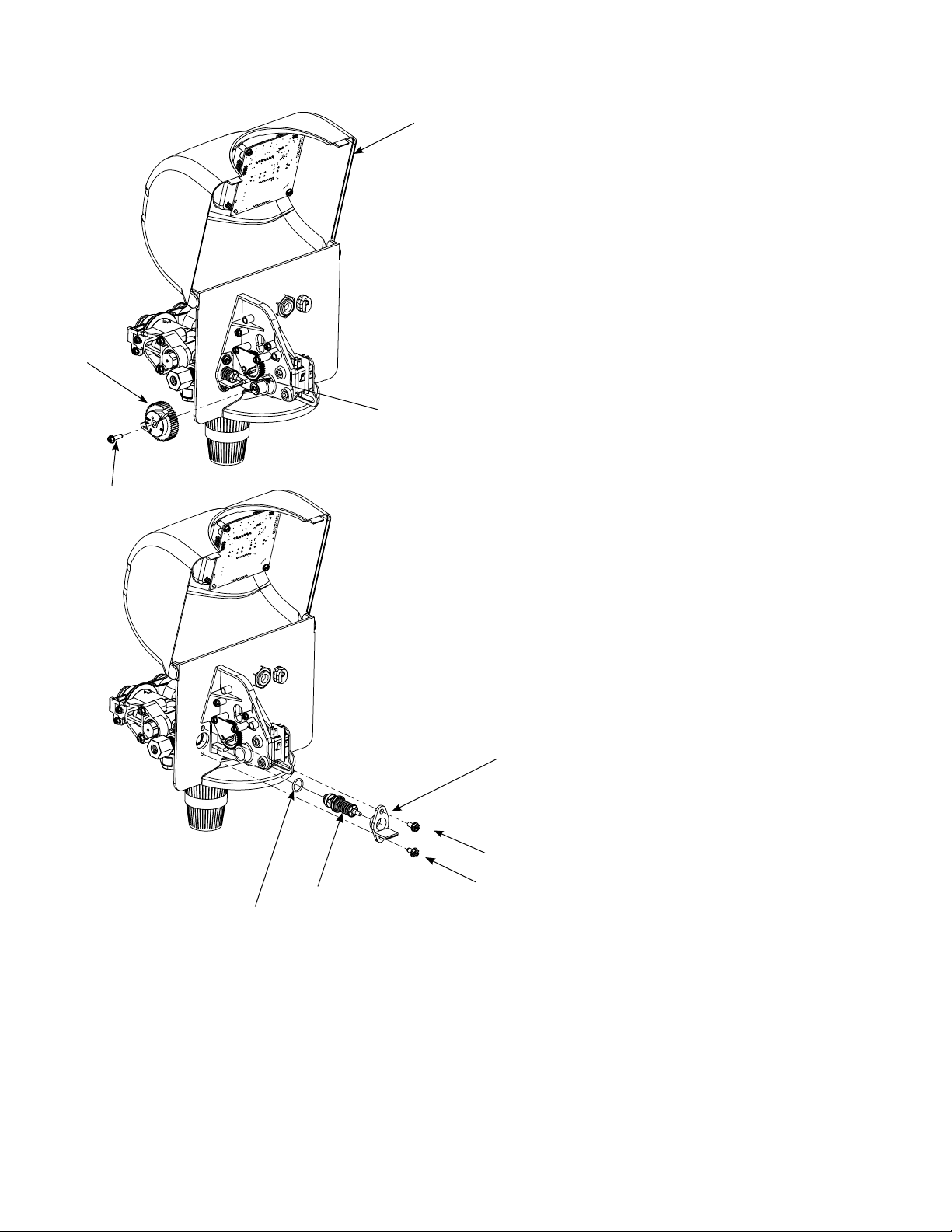
Replacing Brine Valve
Brine Cam
Screw
Front Cover
Brine Valve
1. Open the front cover of the powerhead, unscrew the
brine cam and push the brine valve in order to remove
the cam.
2. Remove the two screws from the grey brine valve bracket
and remove it from the valve back plate.
3. Pull brine valve from injector body. Also remove and
discard o-ring at bottom of brine valve hole.
4. Apply silicone lubricant to new o-ring and install at
bottom of brine valve hole.
5. Apply silicone lubricant to o-ring on new valve assembly
and press into brine valve hole. Be sure shoulder on bushing is flush with injector body.
6. Reinstall the brine valve bracket. Make sure to use self
tapping screw at the bottom of the bracket. Reinstall
brine cam. Close the front cover of the control valve.
O-ring
Brine Valve
Bracket
Screw
Self tapping screw
31
30
Page 32
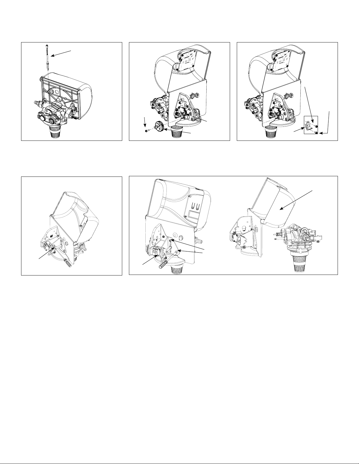
Timer Replacement
Meter Cable
Screw
Screw
Self
tapping
screw
Brine
Valve
1. Disconnect the meter cable from
the meter.
Piston screw
4. Remove the piston screw from the
piston rod.
Brine Cam
2. Open the front cover of the control
valve, unscrew the brine cam and
push the brine valve in order to
remove the cam.
Screw
Screw
5. Remove the three screws from the front bracket. The entire timer assembly will
disconnect from the valve body.
6. Replace the timer with a new one. Attach the three screws to the front bracket
and piston screw to the piston rod. Reinstall the brine valve bracket. Reinstall
brine cam. Close the front cover of the control valve.
7. Reconnect meter cable.
3. Remove the two screws from the
grey brine valve bracket and
remove it from the valve back plate.
Bracket
Timer Assembly
32
31
Page 33
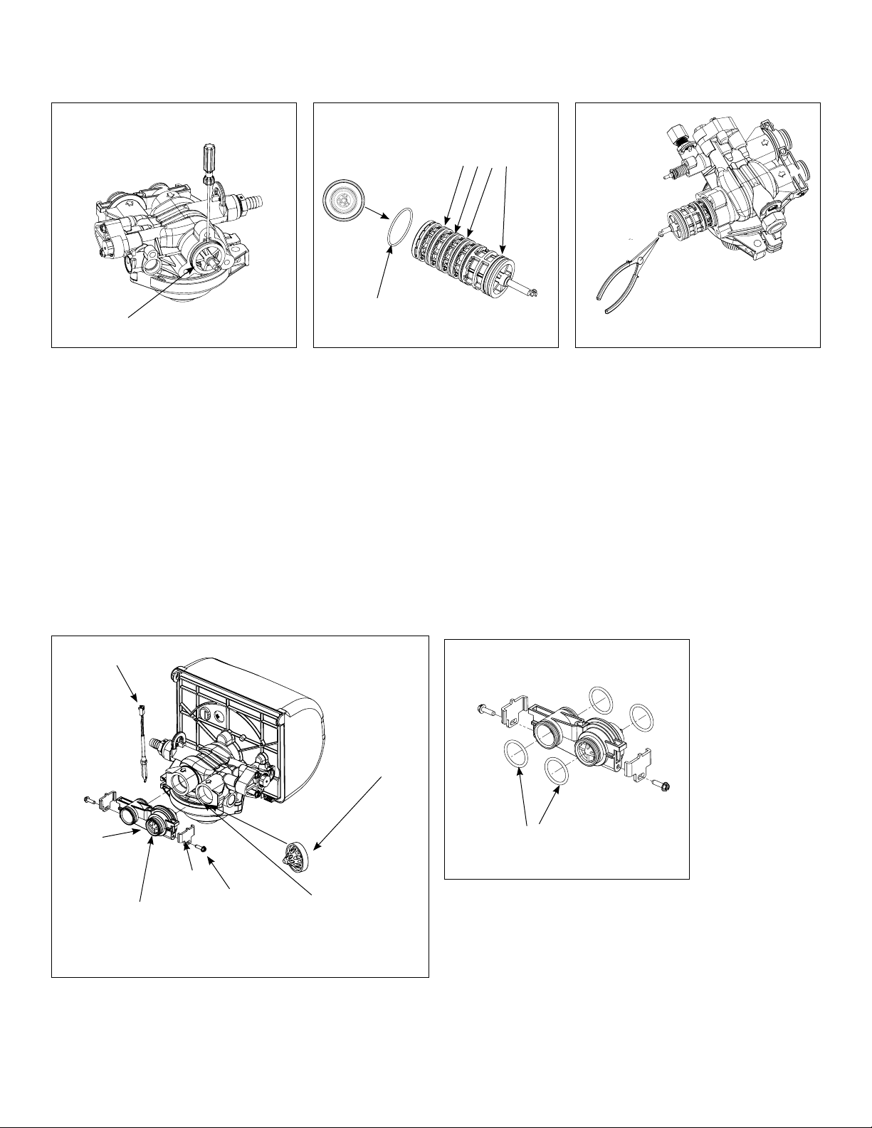
Piston Cartridge Assembly Replacement
B
4
3
2
1
5
D
C
6
REVISIONS
DATE
APP'D
DESCRIPTION
REV.
ECN
ZONE
All 5 O-rings need to be
inspected for damages
and lubricated
This O-ring goes to the
bottom of the cartridgeCartridge Assembly
1. Follow steps 1 to 5 of timer
replacement.
2. Use a flat head screw drive on the
notch of the valve body as shown
to loosen the piston cartridge, pull
the cartridge out of the body using
pliers.
3. Inspect the inside of the valve to
make sure that there is no foreign
matter that would interfere with the
valve operation.
4. Put food grade silicone grease on
the o-rings of the new piston cartridge assembly and install it inside
the valve body.
Meter Replacement and Service
Meter Cable
5. Reinstall the timer assembly, brine
valve bracket and meter cable.
Outlet Port
Lubricate O-rings
Meter
Assembly
Clip
Flow Meter should be
attached to the outlet
side of the valve
Screw
Flow Straightainer
Inside the Outlet
Port
4. Apply silicone lubricant to four new o-rings and assemble
to four ports on new meter module.
5. Assemble meter to control valve. Note, meter portion of
module must be assembled at valve outlet.
6. Push resin tank back to the plumbing connections and
engage meter ports with bypass valve or yoke.
1. Disconnect the meter cable from the meter.
2. Remove two screws and clips at bypass valve or yoke.
Pull resin tank away from plumbing connections.
3. Pull meter module out from control valve.
7. Attach two clips and screws at bypass valve or yoke. Be
sure clip legs are firmly engaged with lugs.
33
32
Page 34
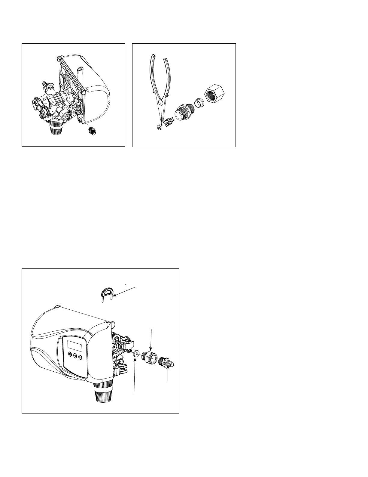
Servicing and Replacing Brine Line Flow Control (BLFC)
1. Disconnect the brine line
retainer clip.
2. Remove the BLFC assembly and pull
the flow washer retainer out of the
BLFC housing with the help of plier.
Servicing and Replacing Drain Line Flow Control (DLFC)
1. Disconnect the drain line retainer clip.
DLFC
Retainer
Flow Washer
Housing
2. Remove the DLFC assembly and pull the flow washer out
of the DLFC housing with the help of plier.
3. Remove the flow washer from the housing and clean it
with water to remove any debris. Replace it with a new
washer if necessary.
4. Re-install the DLFC housing and retainer
3. Remove the flow washer from the
retainer and clean it with water to
remove any debris. Replace it with a
new washer if necessary.
4. Re-install the BLFC housing
and retainer.
Flow Washer
Hose
Barb
34
33
Page 35
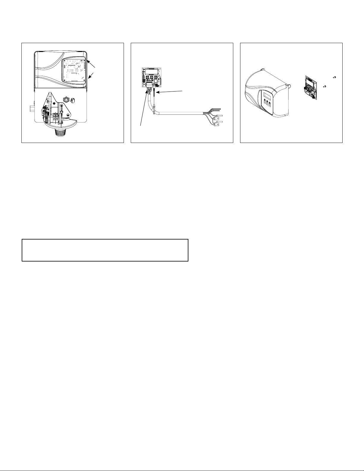
Circuit Board Replacement
Screws
Meter Cable
Power Harness
1. Detach the circuit board from valve
front cover by removing two screws.
2. Disconnect the meter cable and
power head harness from the
circuit board.
3. Replace and connect the new
circuit board on the front cover.
After Servicing
1. Reconnect brine tube and drain line.
2. Return bypass or inlet valve to normal in service position. Water Pressure will automatically build in the softener.
NOTE: Be sure to shut off any bypass line.
3. Check for leaks at all sealed areas. Check Drain seal with the control in the backwash position.
4. Plug electrical cord into outlet.
5. Set Time of Day and cycle the control valve manually to assure proper function. Make sure control valve is returned to
the In Service position.
6. Verify the salt level in the brine tank is sufficient. Start regeneration cycle manually if water is hard.
35
34
Page 36
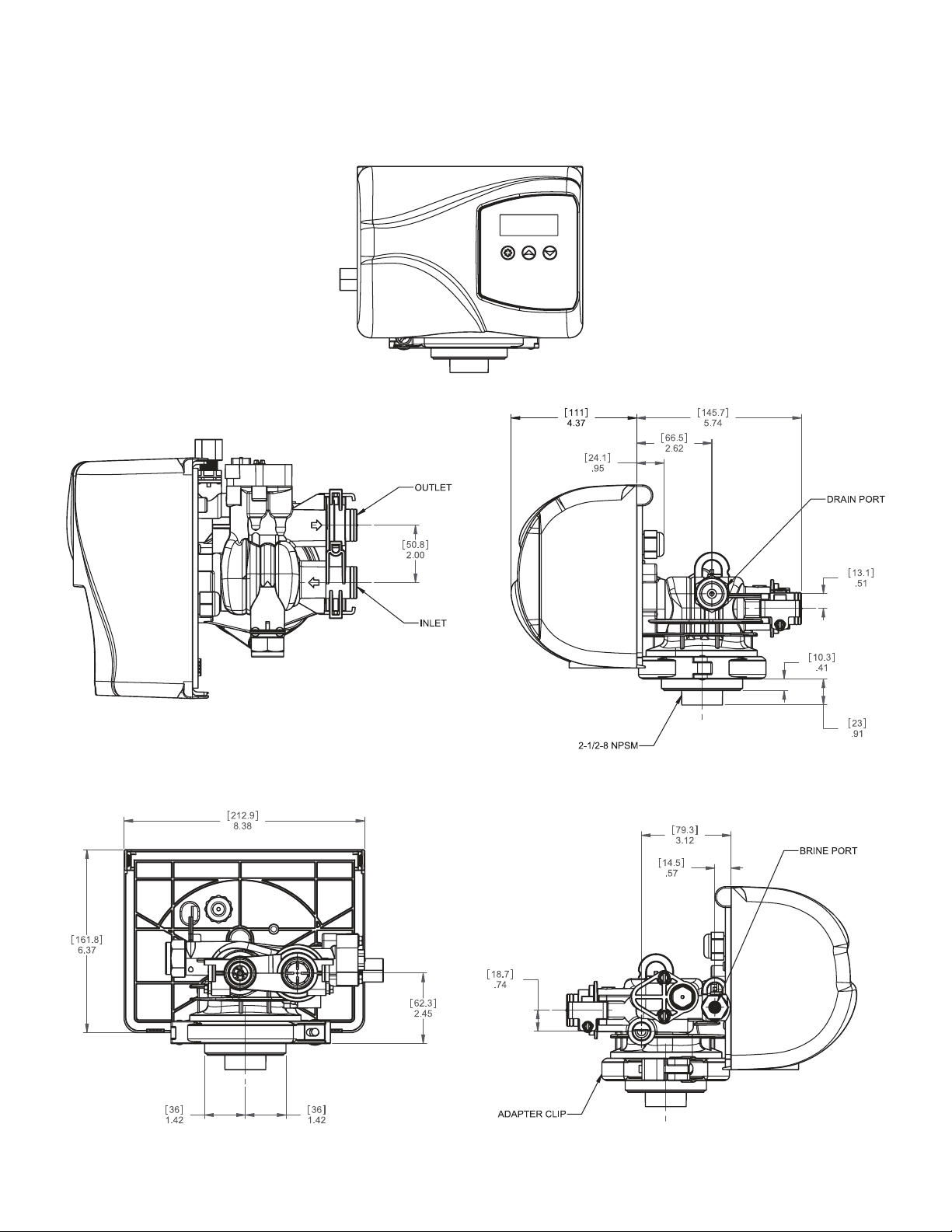
6200 SXT Valve Dimensional Drawings
All dimensions are in
Inches (mm).
36
36
35
Page 37
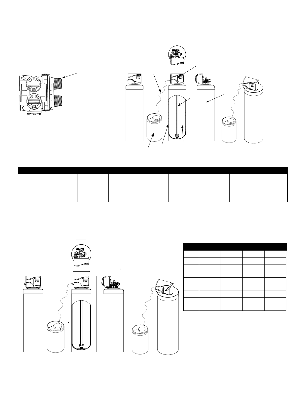
Parts Breakdown
12
2
1
4
5
Common Components
Item No. Part No. Description
N/A 95020 Pro-Pot Perm
10 60626 Meter
11 60049 Bypass
Item # Model # Feeder (1) Valve (2) Tank (3) Distributor (4) Jacket (5) Media (6) Tubing (7)
4636 DISF75SXT 33030 6200219 18474 19478 100502 95411 115208
4637 DISF10SXT 33017 6200220 110474 19478 100507 95412 115208
4638 DISF15SXT 33031 6200221 112524 19477 95413 115208
4639 DISF20SXT 33017 (2) 6200222 114501 19478 95414 115208
1
3
6
F
G
E
A
B
C
D
Dimesions (inches)
Model
DISF75SXT DISF10SXT DISF15SXT DISF20SXT
Item #
A 8 9 10 12
B 54 55 61 59
C 19 19 19 19
D 49 50 56 54
E 2 2 2 2
F 10 10 10 10
G 18 18 18 18
4636 4637 4638 4639
11
36
Page 38
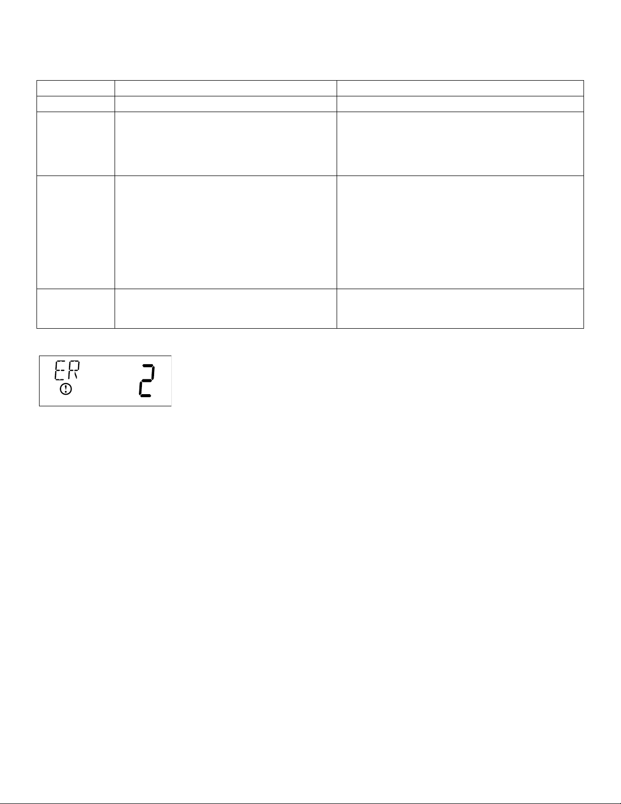
Error Codes
Note:ErrorcodesappearontheInServicedisplay
Error Code Probable Cause Recover and Resetting
[Err0] Drivemotorisstalled Unplugtheunitfromthepowersource
[Err1] Drivemotorisrunningcontinuously Whenpowerisrestoredtotheunit,theErr_display
codeclears.Iftheconditioncausingtheerrorhas
notbeenresolvedtheErr_codereappearsinthe
fourdigitdisplay.Donotattempttotroubleshootthis
problemanyfurther.
[Err2] Therehavebeenmorethan99dayssince
thelastRegeneration.IftheDayoftheWeek
modeofregenerationisselectedanddays
sincelastregenerationexceeds7days.
[7--5]:Therehavebeenmorethan7days
sincethelastregeneration.Allindividual
settings(d1,d2,d3,d4,d5,d6,d7)aresetto
0.
[Err3] Controlboardmemoryfailure. PerformaMasterReset.Iftheerrorreturns,
Regenerationmustoccurfortheunittorecover,the
displaytoclearandthevalveto
functionnormally.
[7--5]:Torecoverfrom[Err2],theusermust
initiatearegenerationorsetatleastoneindividual
dayto1.
donotattempttotroubleshootthisproblemany
further.
Error Display Example
NOTE:Unitwillflashwhenanerrorexists.
37
8
Page 39

Trouble Shooting Guide
PROBLEM CAUSE CORRECTION
1. Filter fails to regenerate or A. Electrical service to unit has A. Assure permanent electrical service
regenerates at wrong times been interrupted (check fuse, plug or switch)
B. Timer is defective B. Repair or replace timer
C. Power failure C. Reset time of day
D. Timer motor does not run D. Replace defective motor
2. Filter bleeds iron or odor A. Bypass valve is open A. Close bypass valve
B. Container is depleted B. Replace or refill container
C. Excessive water usage C. Increase frequency of regeneration
and/or settings. Make sure there are no
leaks in toilets and sinks
D. Insufficient water flowing into D. Check refill setting. Check for plugged
chemical container container tube and flow control
E. Hot water tank rusty E. Repeated flushings of the hot water tank
are required. Do not use hot water during
regeneration
F. Leak at distributor tube F. Make sure distributor tube is not cracked.
Check O-ring and tube pilot
G. Defective or stripped media bed G. Replace media
H. Not backwashing enough H. Be sure flow control is not clogged or
drain line restricted. Be sure water
pressure has not dropped and that pump
has sufficient capacity.
I. Internal valve leak I. Replace seals and spacers and/or piston
J. Electrical Service to unit has J. Assure permanent electrical service
(check been interrupted fuse, plug or
switch)
K. Control will not draw chemical K. Maintain water pressure at 20 psi (139.9
properly (see below) kPa) minimum. Clean or replace injector
assembly. Check for air leaks along brine
line and tighten all connections.
L. Quality of water has worsened L. Have water sample analysed to
determine any change
M. Filter capacity is too small M. Replace with larger unit
3. Filter regenerates every day A. Faulty gear train A. Check the mechanical linkage on the
timer control to eliminate possible binding
in the gear train.
4. Iron filter uses too much A. Defective chemical container A. Replace container
chemical
5. loss of water pressure A. Iron or turbidity build-up in filter A. Increase frequency of regeneration so
filter backwashes more often. NOTE:
Make sure filter is sized large enough to
handle water usage
B. Inlet to control blocked with iron B. Clean inlet line. Remove piston and clean
build-up or foreign matter control.
6. Loss of media through line A. Air in water system A. Assure that well system has proper air
eliminator control. Check for dry well
condition.
B. Backwash rate too fast B. Check drain flow control for proper flow
rate
13
38
Page 40
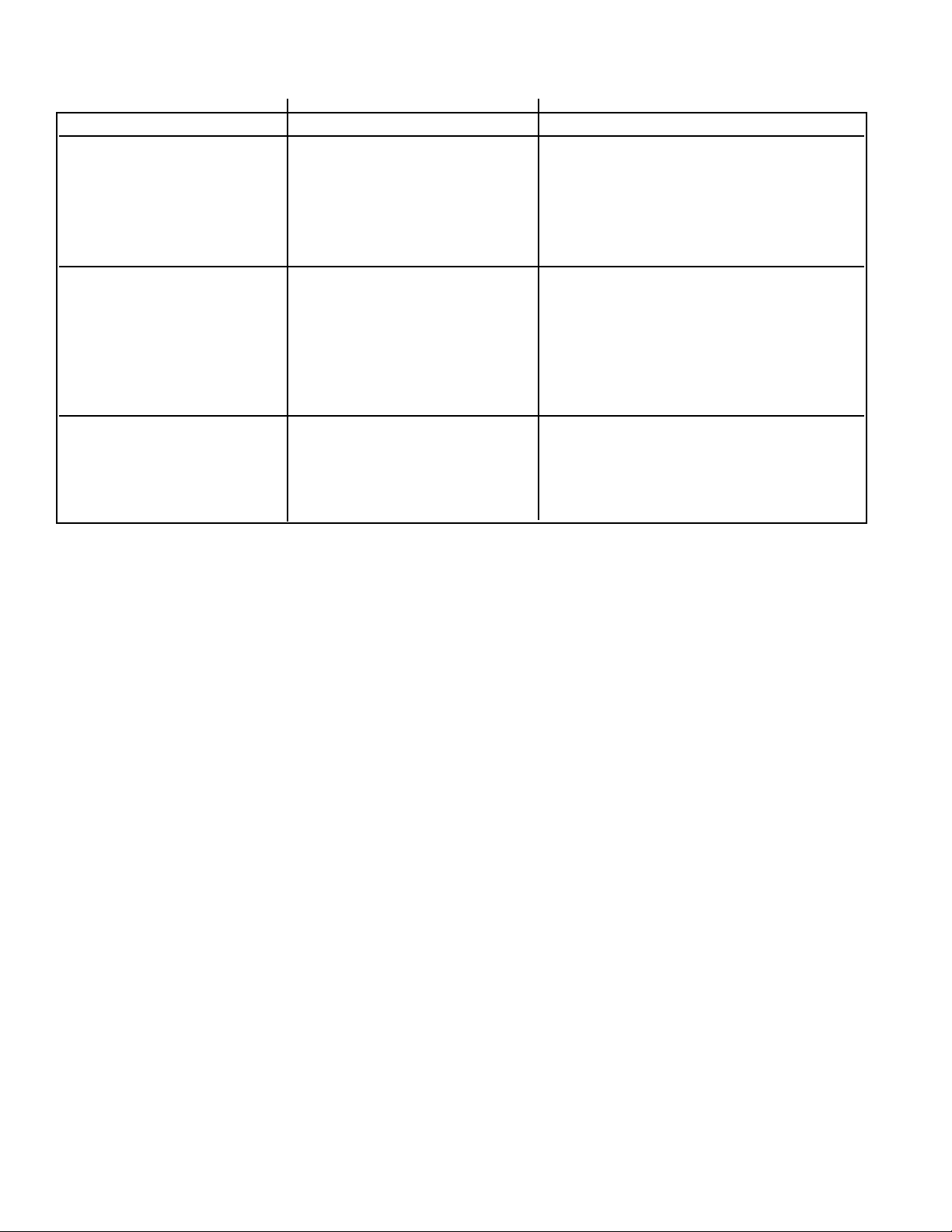
Trouble Shooting Guide
PROBLEM CAUSE CORRECTION
7. Iron filter fails to draw A. Drain line flow control is A. Clean drain line flow control
chemical plugged
B. Injectors and/or screen plugged B. Clean or replace injectors and/or screen
C. Line pressure is too low C. Maintain line pressure at 20 psi (139.9
kPa) minimum
D. Internal control leak D. Change seals and spacers and/or piston
assembly
8. Drain flows continuously A. Foreign material in control A. Remove piston assembly and inspect
bore, remove foreign material and check
control in various regeneration positions
B. Internal control leak B. Change seals and spacers and/or piston
assembly
C. Control valve jammed in brine C. Replace piston and seals and spacers
or backwash position (and drive motor if necessary)
D. Timer motor stopped or jammed D. Replace timer motor
9. Pink color (potassium A. Poor water pressure or A. Be sure pump is set at 20 psi (139.9
permanganate) present insufficient pump capacity kPa) minimum and is capable of
after regeneration; medicinal producing 5 - 12 USGPM according
water taste to filter size
B. Chemical in water supply B. Decrease frequency of regeneration
39
Page 41

Duro Guarantee
WaterGroupInc.guaranteesthatyournewwaterconditionerisbuiltofqualitymaterialandworkmanship.
Whenproperlyinstalledandmaintained,itwillgiveyearsoftroublefreeservice.
Seven Year Complete Parts Guarantee:
WaterGroupInc.willreplaceanypartwhichfailswithin60monthsfromdateofmanufacture,asindicated
bytheserialnumberprovidedthefailureisduetoadefectinmaterialorworkmanship.Theonlyexception
shallbewhenproofofpurchaseorinstallationisprovidedandthenthewarrantyperiodshallbefromthedate
thereof.
Ten Year Guarantee on Mineral Tanks and Brine Tanks:
WaterGroupInc.willprovideareplacementmineraltankorbrinetanktoanyoriginalequipmentpurchaserin
possessionofatankthatfailswithin120months,providedthatthewaterconditionerisatalltimesoperatedin
accordancewithspecificationsandnotsubjecttofreezing.
General Provisions:
WaterGroupInc.assumesnoresponsibilityforconsequentialdamage,labororexpenseincurredasaresultof
adefectorforfailuretomeetthetermsoftheseguaranteesbecauseofcircumstancesbeyonditscontrol.
Page 42

U.S. Headquarters
WaterGroup Companies, Inc.
193 Osborne Road
Fridley, MN 55432, USA
TOLL FREE PHONE: 1-877-581-1833
Canada Headquarters
WaterGroup Companies, Inc.
490 Pinebush Road, Unit 1
Cambridge, ON N1T 0A5, Canada
TOLL FREE PHONE: 1-877-288-9888
www.watergroup.com
Distribution Locations
Durham, NC
Libertyville, IL
Pottstown, PA
Rancho Cucamonga, CA
Cambridge, ON
Calgary, AB
Regina, SK
52308.0512
Printed in Canada
 Loading...