

Page 1

Warranty
• DuraTrax®will warranty this kit for 90 days after the purchase date from defects in materials or
workmanship. DuraTrax
will either repair or replace, at no charge, the incorrectly made part. Exception: Specific parts covered under the
Graphite Parts and Stress Tech™Guarantee, see page 3.
• Make sure you save the receipt or invoice you were given when you bought your model! It is your proof of purchase
and we must see it before we can honor the warranty.
• To retur n your Evader ST Pro for repairs covered under warranty you should send your truck to:
Hobby Services
3002 N. Apollo Drive Suite 1
Champaign, Illinois 61822
Attn: Ser vice Depar tment
Phone: (217) 398-0007 9:00 am-5:00 pm Central Time M-F
E-mail:
hobbyservices@hobbico.com
If the buyer is not prepared to accept the liability associated with the use of this product,the buyer is advised to
return this kit immediately in new and unused condition to the place of purchase.
READ THR OUGH THIS MANUAL BEFORE STARTING.IT CONTAINS IMPORT ANT INSTRUCTIONS AND WARNINGS
CONCERNING THE ASSEMBLY AND USE OF THIS MODEL.
v1.0 © Copyright 2004 DTXZ3104 For DTXC0027
ASSEMBLY AND OPERATION MANUAL
Length: 15.2" [385mm]
Width: 13" [330mm]
Height: 5.8" [147mm]
Weight: 3.3 lb [1500g]
Wheelbase: 11.6" [295mm]
T
echnical Support Information
For technical assistance, contact:
DuraTrax Product Suppor t
3002 N. Apollo Drive, Suite 1
Champaign, IL 61822
(217) 398-8970, Ext. 5
carsupport@duratrax.com
™
®
PREB
PREB
UIL
UILTT
Page 2

INTRODUCTION................................................................2
IMPORTANT SAFETY PRECAUTIONS............................2
HELPFUL HINTS...............................................................2
GRAPHITE & STRESS TECH PARTS GUARANTEE.......3
REPAIR SERVICE .............................................................3
SPECIFICATION & DESCRIPTION CHANGES ...............3
ADDITIONAL ITEMS REQUIRED.....................................3
Tools Needed for Completion ...................................3
Tools Included for Maintenance & Cleaning...........3
PREPARE THE RADIO SYSTEM......................................4
CHARGE Y OUR BA TTERY................................................4
STEERING SERVO INSTALLATION.................................4
RECEIVER INSTALLATION..............................................5
ELECTRONIC SPEED CONTROL INSTALLATION.........6
MOTOR INSTALLATION ...................................................6
BATTERY INSTALLATION................................................7
P AINT THE BOD Y..............................................................7
BALL DIFFERENTIAL BREAK-IN....................................8
MAINTENANCE TIPS........................................................8
Before Each Run ........................................................8
After Each Run ...........................................................8
After Every Ten Runs.................................................8
ASSEMBLY GUIDE ...........................................................9
Front Knuckle Arm, Hub Carrier, Axle .....................9
Steering Bellcrank Assembly...................................9
Servo, Servo Plate, Upper Plate .............................10
Rear Shock Tower, Bulkhead, & Suspension Arm ...10
Front Shock Tower, Bulkhead, & Suspension Arm ..11
Ball Differential.........................................................11
Slipper Clutch...........................................................12
Rear Hub, Rear Axles ..............................................12
Gearbox ....................................................................13
Shocks......................................................................14
TUNING GUIDE...............................................................15
Caster........................................................................15
Camber......................................................................15
Front / Rear Toe-In and Toe-Out..............................15
Rear Anti-Squat........................................................15
Wheel Base...............................................................15
Battery Placement....................................Back Cover
Ride Height...............................................Back Cover
Camber Link Placement..........................Back Cover
Slipper Adjustment..................................Back Cover
Front Shock Adjustment .........................Back Cover
Rear Shock Adjustment ..........................Back Cover
Shock Oils & Shock Springs...................Back Cover
Shock Pistons ..........................................Back Cover
Adjustable Steering Rate ........................Back Cover
Steering Adjustment (Ackerman)...........Back Cover
Thank you for purchasing the DuraTrax Evader ST Pro.This
manual contains the instructions you need to build, operate
and maintain your new electric R/C vehicle. Read over this
manual thoroughly before building or operating the Evader
ST Pro.
When the safety precautions are followed, the Evader ST
Pro will provide years of enjoyment. Use care and good
sense at all times when operating this radio controlled truck.
Failure to use this vehicle in a safe, sensible manner can
result in injury or damage to property. You and you alone
must insure that the instructions are carefully followed and
all safety precautions are obeyed.
• Do not operate the Evader ST Pro near people.
Spectators should be behind the driver or at a safe
distance away from the vehicle.
• Make sure to read the instructions with the battery and
charger before charging.
• Do not leave the charger unattended during charging. If
the battery or charger become hot at any time, disconnect
the battery from the charger immediately! Failure to do so
may cause permanent damage to the charger and battery
and may cause bodily harm.
• Do not cover the air intake holes on the charger during
charging.This may cause the charger to overheat.
• Do not allow the electronic speed control (ESC) or radio
equipment to come into contact with moisture.Water can
cause the electronics to short out and can cause
permanent damage.
• Always turn on the transmitter before turning on the
electronic speed control.
• Before turning on your radio, check to make sure that no
one else is running on the same frequency as your
Evader ST Pro.
• A void w orking ov er a deep pile carpet.If you drop a small
part or screw, it will be difficult to find.
• Place a mat or towel over y our work surface .This will prevent
parts from rolling off and will protect the work surface.
• Avoid running the truck in cold weather.The plastic and
metal parts can become brittle at low temperatures. In
addition, grease and oil become thick, causing
premature wear and poor performance.
• Test fit all par ts before attaching them permanently.
HELPFUL HINTS
SAFETY PRECAUTIONS
INTRODUCTIONTABLE OF CONTENTS
2
Page 3
We hav e engineered the Ev ader ST Pro to tak e the rough and
tumble abuse that makes R/C fun.We are so confident of the
quality and durability of the Graphite and Stress-Tech par ts
that we will replace any Graphite or Stress-Tech part you
break during the first 12 months you own the vehicle. Just
send in the part to us and we will send you a FREE
replacement. Please see the Evader ST Pro par ts list for the
items covered under the Graphite and Stress-Tech guarantee.
To receive your free replacement part, please send the
following to the Hobby Services address listed on the cover
of this manual.
❏ 1.The broken part must be included.
❏ 2.The part number and description of the broken part.
❏ 3. Dated copy of your invoice or purchase receipt.
❏ 4.Your name, phone number and shipping address.
Repair service is available anytime.
After the 90 day warranty, you can still have your Evader ST
Pro repaired for a small charge by the experts at DuraTrax's
authorized repair facility, Hobby Services, at the address
listed on the front page of this manual.
To speed up the repair process, please follow the
instructions listed below.
❏1. Under most circumstances return the ENTIRE system:
vehicle and radio. The exception would be sending in a
Stress-Tech or Graphite part.See the instructions under
Graphite and Stress-Tech Parts Guarantee above.
❏ 2. Make sure the transmitter is turned off and all of the
batteries are removed.
❏ 3. Send written instructions which include: a list of all
items returned, a THOROUGH explanation of the
problem, the service needed and your phone number
during the day. If you expect the repair to be covered
under warranty, be sure to include a proof of date of
purchase (your store receipt or purchase invoice).
❏ 4. Also be sure to include your full return address.
All pictures, descriptions and specifications found in this
instruction manual are subject to change without notice.
DuraTrax maintains no responsibility for inadvertent errors
in this manual.
To operate the Evader ST Pro,
the following items are required:
❏ DuraTrax 6 cell batter y pack (DTXC2081)
❏ DuraTrax 6-7 cell charger (DTXP4100)
❏ Electronic speed control
❏ Motor
❏ 2-Channel radio with one servo
❏ Hobby knife (HCAR0105)
❏ #11 Blades (HCAR0211)
❏ #2 Phillips head screwdriver (DTXR0124)
❏ Needle nose pliers (DTXR0300)
❏ 3/32", 1.5mm & 2.5mm hex Wrenches
❏Turnbuckle wrench
❏ Nut driver (4-way)
Tools Included for Maintenance & Cleaning
Tools Needed for Completion
ADDITIONAL ITEMS REQUIRED
SPECIFICATION & DESCRIPTION
CHANGES
REPAIR SERVICE
GRAPHITE AND STRESS-TECH
™
PARTS GUARANTEE
3
Page 4
❏
1. Install the “AA” batter ies in the transmitter.
❏
2. Install and extend the transmitter antenna.
❏
3. Connect the steering servo and electronic speed control
to the receiver. See your radio instructions to see which
channel is steering (servo) and which is throttle (ESC).
❏
4. Uncoil and extend the receiver antenna.
❏
5. Hook up the charged 6 or 7 cell battery to the electronic
speed control.
❏
6. Adjust the servo trims of the transmitter to the neutral
position (centered).
❏
7. Switch on the transmitter.
❏
8. Switch on the electronic speed control.
❏
9. Set up speed control (see your ESC instructions for the
correct set-up procedure).
❏
10.Operate the steering and throttle control.Make sure the
steering servo arm and motor move in proportion to the
movement of the steering wheel and throttle trigger.
❏
11. Switch off the receiver, then the transmitter.
❏
12.See your radio instructions for set-up and oper ating the
radio system.
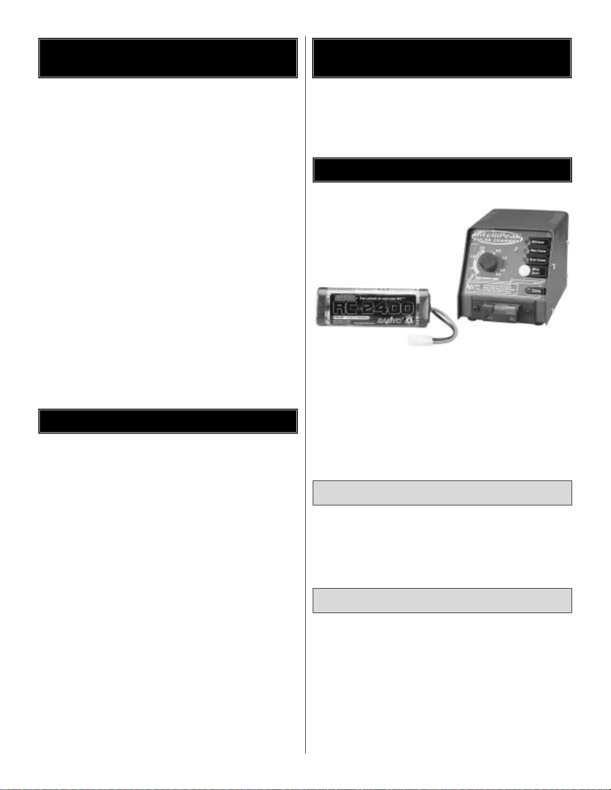
❏ 1. Charge the 6- or 7-cell
battery (not included) on
your charger (not included).
See Safety Precautions
before charging.See your
charger's instructions for
proper charging procedure
and charge times.
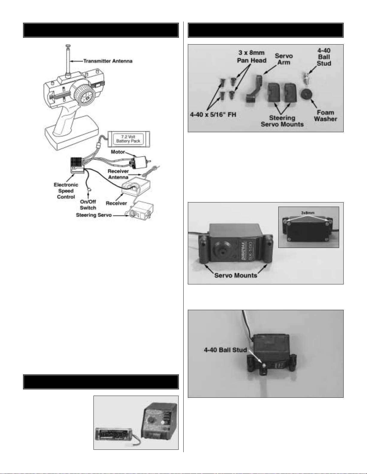
❏
1. Locate and remove from the parts bag two (2) steering
servo mounts, one (1) servo arm (determine which servo arm
is required for your radio system), one (1) 4-40 ball stud, one
(1) foam washer, two (2) 3x8mm pan head screws and two
(2) 4-40 x 5/16"flat head machined screws To ensure that
you are using the right size screw, match the screw to the
picture on the hardware chart, which is on the separate
exploded view/parts list.
❏
2. Attach the servo mounts to the servo using the two (2)
3x8mm screws as shown.
❏
3. Install the 4-40 ball stud into the flat side of the steering
servo arm in the upper hole. With the steering servo centered
as described in “Preparing the Radio System”, install the
correct steering servo arm onto the ser vo splines as shown
above.(Note: If the steering servo is not properly centered, the
steering could be off).Re-install the servo horn screw , securing
the horn onto the servo.
STEERING SERVO INSTALLATION
CHARGE Y OUR B A TTERY
PREPARING THE RADIO SYSTEM
4
Page 5
❏
4. Remove the two (2) 4-40 x 3/4
"
socket head machined
screws from the upper plate and rotate the front of the truck
forward. (Note: Be careful that you do not loosen any of
the steering assembly parts during this process).
❏
5. Install the steering servo into the mounting slot. Line up
the holes in the servo mounts with the two holes in the chassis.
(Note: there are two different mounting holes in the servo
mounts. Use the appropriate holes for your servo). Install the
two (2) 4-40 x 5/16"flat head machined screws through the
bottom of the chassis into the servo mounts. Attach the
steering link ball cup onto the 4-40 ball stud on the servo.
❏
6.Install the servo brace onto the chassis using the two (2)
4-40 x 3/8"socket head machined screws and two (2)
4-40 x 3/4"socket head cap screws. Re-install the two (2)
4-40 x 3/4"socket head cap screws into the upper plate.
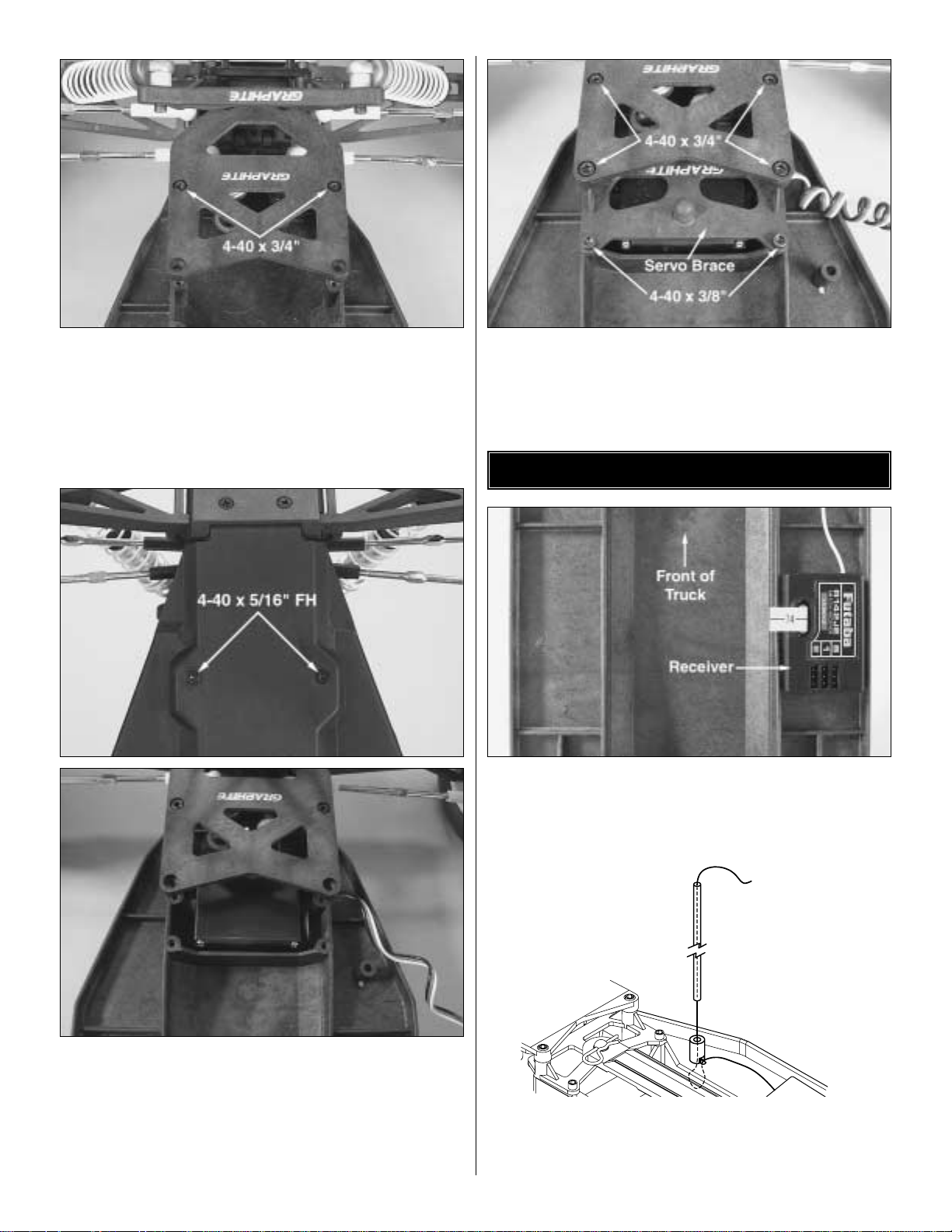
❏
1. Install the receiver onto the chassis as shown. Remove
the protective backing from one side of the included 1/4" thick
piece of foam tape and install it onto the chassis. Then
remove the other piece of protective backing and install the
receiver onto the foam rubber.
❏
2. Route the receiver antenna through the holes in the
chassis as shown above. Locate the antenna tube, and
thread the receiver antenna through the antenna tube. The
antenna will be longer than the antenna tube. DO NOT CUT
Route the antenna
through the chassis
and then through
the tube.
RECEIVER INSTALLATION
5
Page 6

OR COIL THE ANTENNA WIRE. Press fit the antenna tube
into the hole in the chassis. Tip: Run the antenna wire
through your fingers to straighten out the kinks before
running through the antenna tube. Also, applying a small
amount of soap and water to the antenna wire will help
lubricate the wire for threading into the antenna tube.
❏
1. Mount your ESC to the chassis using the included
double sided tape. If the speed control is too large to mount
to the chassis it can be mounted to the front of the rear shock
tower. When mounting the ESC make sure there is sufficient
air flow across the ESC to keep it cool.
❏
2.Plug the ESC receiv er lead into channel #2 of the receiver .
❏
1. Remove the rear wheel that is on the same side as the
spur gear, this will make installing the motor, pinion and gear
cover easier.
❏
2.Using the two included 3x8mm screws , secure the motor
to the motor plate. Note: Do not tighten the motor screws
down yet.
❏
3. Install the included pinion onto the motor shaft. Make
sure the set screw is placed over the flat spot on the motors
shaft. Line the pinion up with the spur gear so that it is
properly lined up with the spur gear. Note: See the pictures
above to help determine if the spur and pinion are properly
lined up.
❏
4. Set the gear mesh between the spur and pinion. The
mesh is set by sliding the motor forward and back. When
setting the gear mesh you want to make sure it is not set too
tight or too loose (either will cause the spur gear to strip easily).
MOTOR INSTALLATION
ELECTRONIC SPEED CONTROL (ESC)
INSTALLATION
6
Page 7

To set the gear mesh properly, slide the pinion until it fully
meshes up against the spur then back it up slightly. Run a
piece of paper between the two gears. If the paper is ripped,
the mesh is too tight.If the paper is not tightly creased the gear
mesh is too loose.Once the gear mesh is set, tighten the motor
screws.
❏
5. Install the gear cover onto the motor plate and secure it
in place with the included 3x3mm screws.
❏
6. Re-install the rear wheel back onto the truck.
❏
7. Connect the motor to your ESC according to the ESC's
instructrion manual.
❏
1. Remove the body pin from the battery strap post, and
remove the battery strap from the Evader ST.
❏ 2
.Install the charged 6 or 7 cell battery into the battery slot.
Re-install the battery strap onto the Evader ST. Note that
there is a channel in the rear of the chassis for the
battery strap to rest in. Re-install the body clip into the
battery strap post.
❏
1. Clean the body thoroughly using a small amount of dish
soap and water. Make sure that all of the soap is rinsed out
of the body. Let the body completely air dry.
❏
2. Apply the included window masks to the inside of the
body. Try to get as much air as possible out from under the
mask during application.
❏
3.Use Hobbico Master Mask liquid masking film or a quality
masking tape to mask the inside of the body to your desired
paint scheme.
❏
4. Spray a light coat of lexan compatible paint onto the
inside of the body and let it completely dry before applying
the next coat. Continue applying light coats until the desired
area of the body is adequately covered.
❏
5.Once the body is painted as desired, remove the windo w
masks and apply the desired decals.
❏
6.Secure the body to the chassis using the included body clips.
P AINT THE BOD Y
BATTERY INSTALLATION
7
Remove the pin and
lift the strap to
install/remove the
battery pack.
Install the strap
between the bumps.
Page 8

The ball differential has been adjusted at the factory for proper
“break-in”. Do not tighten the differential before the truck has
been properly broken-in or you can damage the differential.
After running the truck for 2 or 3 battery packs, the ball
differential will require readjustment. This is the “normal”
break-in period for the ball differential. You will hear a
“squealing” sound when accelerating from a stop and the
truck will accelerate slower. This indicates that the
differential is properly broken-in and now requires
adjustment.Do not run the truck again until the differential is
properly readjusted as follows.
Adjusting the differential is quick and easy. Access the
adjusting screw by disconnecting the rear camber link
(using pliers) at the right rear wheel. Rotate the wheel and
CV shaft out of the way.
While holding the left rear tire, tighten the adjusting screw by
inserting the included 3/32" L-wrench into the cap screw on
the right side of the ball differential. The screw should be
tightened until it is “just snug.” Caution: Do not over tighten
the adjusting screw or you will damage the differential.
Next, loosen the screw 1/8 of a turn.
Reinstall the CV shaft back into the differential and reattach
the camber link. The ball differential may need occasional
adjustment to maintain performance.
BEFORE EACH RUN
❏ 1
. Check to make sure that all screws are tight and there
are not any screws missing.
❏
2. Check to make sure that the transmitter batteries are
not low.
❏
3. Check to make sure that all of the moving parts of the
Evader move freely and do not bind.
❏
4. Check for broken or damaged parts. Replace any
broken or damaged parts before running the Evader ST Pro.
Running of the Evader ST Pro with broken or damaged parts
could result in damage to other parts.
❏
5. Check to make sure that the receiver and speed control
are still properly secured to the chassis.
❏
6.Check to mak e sure that all wires are properly connected.
AFTER EACH RUN
❏
1. Clean any large globs of dirt or debr is from the chassis
and moving parts.
❏
2. Disconnect and remove the battery from the Evader.
❏
3. Check for any broken or damaged parts.This way parts
may be replaced before the next run.
AFTER EVERY 10 RUNS
❏
1.
Check the servo saver for proper operation. During
normal maintenance, check the operation of the servo saver
by grasping the servo arm and linkage and turning one of
the front tires left and right.If the wheels turn without moving
the linkages and servo arm, then the unit is operating
properly. If the linkage and servo arm move, loosen the
knurled adjustment nut on the left side servo saver shaft. If
the servo saver becomes clogged with dirt, it may not work
properly which could cause servo or linkage damage. The
servo saver needs to be disassembled, cleaned and
readjusted. To safely adjust the servo saver, loosen the
knurled aluminum collar on the left side steering post
completely. Then reinstall 1-½ turns onto the post. Retest
the servo saver as described above. Adjust the servo saver
tighter or looser if needed.
❏
2. Check to make sure that the bearings are free of dirt
and debris and roll smoothly.
❏
3. Check the shocks for oil leakage. If the shocks have
leaked any shock fluid out, you should properly refill the
shocks for best performance. Inspect the shock shafts for
deep scratches.
❏
4. Check the motor brushes for wear. If the motor brushes
are severely worn or discolored they should be replaced.
❏
5. Check for buildup and wear on the bearings of the
motor.If the bearings are dirty, use DuraTrax Power Shot™to
clean them, then relubricate the bearings.
❏
6. Check for proper gear mesh between the spur and
pinion gear.
MAINTENANCE TIPS
BALL DIFFERENTIAL BREAK-IN
8
Camber Link
CV-Shaft
3/32" L-Wrench
Page 9

9
Steering Bellcrank Assembly
1. Insert two of the brass bushings (105) into the chassis.Note:The brass
bushings may need to be slightly tapped into place. The bushings
must be fully seated in the chassis.
2. Insert the short aluminum bellcrank post (99) into the right brass bushing
in the chassis.
3. Install ball studs (81) into the right bellcrank (46) in the holes shown.
4. Insert a plastic bushing (47) into each end of the right steering bellcrank.
Again, make sure the bushings are fully seated.
5. Slide the assembled right bellcrank onto the short aluminum bellcrank
post (99).
6. Install ball studs (81) into the lower left bellcrank (44) in the holes shown.
7. Insert the threaded aluminum servo sav er hub (101) into the bottom of the
lower left steering bellcrank (44). Note:The aluminum servo saver hub is
designed to key into the bottom of the lower left steering bellcrank.
Make sure that the hex in the hub fully seats in the bellcrank.
8. Install a ball stud (81) into the upper left steer ing bellcrank (45).
9. Slide the upper left steering bellcrank (45) onto the ser vo saver hub (101).
The upper and lower left steering bellcranks are designed to key together.
10.Place the servo saver spring (98) on top of the two left steering bellcranks.
11. Secure the left bellcrank assembly together with the aluminum servo
saver spring adjuster (102). Note: The servo saver spring adjuster is
machined on one side for the servo saver spring to fit into.Make sure
this side goes down against the servo saver spring.The servo saver
spring will need to be properly adjusted once the entire steering
bellcrank assembly has been installed on to the Evader ST Pro.
12. Insert a plastic bushing (48) into each end of the left steering bellcrank
assembly. Again, make sure the bushings are fully seated.
13. Install the long aluminum bellcrank post (100) into the left brass
bushing in the chassis.
14. Slide the assembled left bellcrank assembly onto the bellcrank post.
15. Attach the left and right bellcranks together with the one piece molded
link (43).
The following information has been provided to help maintain and tune the Evader ST Pro.
ASSEMBLY GUIDE
Front Knuckle Arm, Hub Carrier, Axle
1. Attach the front hub carriers (28) to the front suspension
arms (38) using the (95) front outer hinge pins.
2. Install the front axles (91) into the knuckle arms (24L or 25R).
3. Install two spacers onto each kingpin.
4. Insert the knuckle arms (24L or 25R) into the front hub carriers
(28) and then secure them in place with the kingpins (94). Note:
The spacers go on the top of the hub carriers (28).
5. Secure the kingpins (94) in place using 2.5mm e-clips (S).
6. Install 3mm set screws into the axles (91) to secure them to
the kingpins (94).
7. Attach the front bumper (2) to the front bulkhead using four
4-40x5/16" (B) flat head machine screws.
H
50
2
B
S
38
95
94
28
S
67
81
91
24
M
67
81
46
43
47
99
47
105
105
105
100
48
102
81
98
45
44
101
48
105
Page 10

10
Servo, Servo Plate, Upper Plate
1. Attach the servo mounting lugs (6) to the front of the servo
mounts on the servo using two 3x8 self tapping screws (L).
2. Install a ball stud (81) into the steering servo horn (8).
Install the ball stud into the hole furthest from the center.
3. Install the steering servo horn onto the servo. Note:
Make sure the transmitter, steering servo and servo
horn are properly centered before securing the servo
horn to the servo.
4. Secure the servo to the chassis with two 4-40x5/16" (B)
flat head screws.
5. Attach the servo brace (56) to the chassis by installing two
4-40x3/8" (C) socket head screws into the two rear holes.
6. Connect the servo to the steering bellcrank assembly
using the adjustable steering servo link (5 & 90).
7. Install two brass bushings (105) into the underside of the
upper plate (52). Note: The brass bushings may need to
be slightly tapped into place. The bushings must be
fully seated into the upper plate.
8. Install the upper plate (52) onto the ser vo plate (56) and
steering bellcrank assembly. Make sure the steering
bellcrank posts insert into the bushings in the upper plate.
Secure the upper plate with four 4-40x3/4" (E) socket head
screws and two 4-40x5/16" (B) flat head screws (b ulkhead).
Rear Shock Tower, Rear Transmission Plate, Rear Bulkhead, Rear Suspension Arm.
1. Attach the rear chassis plate (41) to the chassis using four 4-40x3/8" (C) socket head screws.
2. Attach the rear suspension arm mounts (153) to the rear chassis plate (41) using four 4-40x5/16" (B) flat head screws.
3. Attach the rear suspension ar ms (36 or 37) to the suspension ar m mounts (153) using the inner rear hinge pins (97).
4. Secure the inner rear hinge pins (97) in place using four 2.5mm e-clips (S).
5. Install the rear shock tower (40) and rear b ulkhead (42) onto the chassis using f our 4-40x1/2" (D) screws .Note: Make sure the
screws pass through the shock tower,chassis and into the rear bulkhead.
6.Install two ball studs (152) into the appropriate holes in the rear bulkhead.Note:The stock setting is the lower inner holes.
Make sure that the ball studs are in the same hole location on both sides.
E
C
52
56
5
90
81
T
8
L
6
F
53
42
152
67
36
S
153
41
154
S
B
97
40
C
153
37
1
D
S
Page 11

11
Bulkhead, Bulkhead Brace,
Front Suspension Arm,
Front Shock Tower, Front Bumper
1. Attach the front bulkhead (51) to the chassis using the
hinge pin (103).
2. Secure the hinge pin in place using a 2mm set screw.
3. Attach and secure the front suspension arms (38 and 39) to
the front bulkhead (51) using the (104) front inner hinge pins.
4. Secure the rear of the front inner hinge pin with a 2.5mm
(S) e-clip.
5. Install the front bulkhead brace (50) onto the two front
inner hinge pins.
6. Secure the front bulkhead brace using 2.5mm (S) e-clips.
7. Attach the front shock tower (49) to the front bulkhead
using four 4-40x3/8" (C) socket head screws.
8. Secure the front body mount (57) to the shock tower using two 4-40x3/8" (C) socket head screws.
9. Attach the top of the front bulkhead to the upper plate (52) with two 4-40x5/16" (B) flat head machine screws.
Ball Differential
1. Place one of the differential thrust washers (121) onto the 3x25mm cap screw (G).
2. Lubricate the differential thrust washer using silicone grease.Then install the plastic thrust ball holder (19) and 1/16"
thrust balls (113).
3. Lubr icate the other differential thrust washer (121) and install it on top of the 1/16" thrust balls (113) and holder (19).
4. Inser t the screw and thrust ball assembly into the right outdr ive (92).
5. Apply a small amount of silicone grease to one of the differential rings (120) and place it onto the right outdrive.The
grease should hold the differential ring in place.
6. Install a 5x9mm bear ing onto the right outdr ive.
7. Install the 3/32" differential balls (112) into the differential gear (18).
8. Install a 5x9mm bear ing into the center of the differential gear and install the gear onto the left outdrive.
9. Install the other differential ring (120) onto the left differential outdrive (93).
10. Insert the differential spring (123), lock nut holder (22) and the 3mm lock nut (M) into the end of the left differential
outdrive (93).
11. Join the left and right differential outdrives together and tighten the 3x25mm cap screw (G) until the differential gear
cannot be turned while both differential outdrives are being held.The differential will require fine tuning once it has been
installed into the car.
39
104
S
51
67
49
50
F
81
C
S
O
22
53
57
38
120
123
3/32" Hex wrench
The diff can be properly adjusted
by tightening the diff bolt until
snug and then back off 1/8 turn.
G
121
113
120
19
112
93
18
109
92
Page 12

12
Slipper Clutch
1. Install the inner slipper plate (86) onto the top shaft (83). Make sure the notch in the inner slipper plate keys onto the
2x10 spring pin in the top shaft.
2. Place the slipper pad (64) and outer slipper plate (85) onto the top shaft (83).Make sure the slipper pad (64) is properly
centered between the two plates (85 & 86).
3. Install a slipper bushing (86) into the spur gear (16).
4. Slide the spur gear (16) onto the top shaft (83) and secure it to the outer slipper plate (85) using (2) 3x6mm screws (J)
and (2) 3mm lock washers (P).
5. Slide a 3mm flat washer (V), 3mm brass washer (W), and then another 3mm washer (V) onto the top shaft.
6. Install the slipper spring (87), 3mm washer (V), and then the 3mm lock nut (O).Refer to page 16 for adjusting the slipper.
86
Rear Hub, Rear Axles
1. Install the bear ing spacer (88) and two 5x10mm bearings (108) in both of the rear hubs (26L or 27R).
2. Install a ball stud (81) into the center hole of the rear hubs.
3. Place a 3mm plastic spacer (58) on each side of the rear hubs. Secure the rear hubs (26L or 27R) to the rear suspension
arms (36L or 37R) with the 3mm outer rear hinge pins (107).
4. Secure the outer rear hinge pins (107) with 2.5mm e-clips (S).
5. Install the rear axles (79) through the bear ings in the hubs.
6. Slide a rear axle washer (82) onto the axle and then install a 2.5x12mm spring pin (117) into the rear axle.
64
85
16
86
MOTOR
(119)
80
J
P
P
H
W
87
V
O
74
S
79
67
S
117
107
108
88
58
81
58
82
M
108
Page 13

13
Gearbox
Note:When installing the bearings, make sure they are fully seated. If the bearings are not fully seated
the gearbox halves may not properly fit together or may cause binding.
1. Install a 5mm washer (X) onto each end of the top shaft (83)
2. Install a 5x10mm bearing (108) into the upper hole of the right gearbox half (21).
3. Install the top shaft (83) into the 5x10mm bear ing that was just installed into the right gearbox half.
4. Install the 2x10mm spr ing pin (116) into the top shaft
5. Attach the roll pin cover (7) to the right gearbox half.
6. Install a 5x10mm bear ing (108) into each side of the idler gear (17).
7. Install the idler gear shaft (89) into the idler gear bear ings.
8. Install the idler gear into the r ight gearbox half (21).
9. Install a 12x18mm bear ing (110) into the lower hole in the right gear box half (21).
10. Install the ball differential into the 12x18mm bearing that was just installed into the right gear box half (21).
11. Inser t a 12x18mm (110) and 5x10mm bear ing (108) into the left gearbox half (20).
12. Install the two gearbox halves together. Make sure the two gearbox halves seat together properly.
13. Secure the two halves together with the 4-40x1/2" socket head screw (D).
14. Install the aluminum motor plate (96) on the side of the gearbox and attach it with the (3) 3x25mm socket
head screws (G).
7
21
108
X
116
83
X
20
P
96
89
108
108
17
G
110
P
110
D
Page 14

14
Shocks
1. Install a 2.5mm e-clip (S) onto the lower groove on the shock shaft (77 or 78).Install the e-clip into the groove closest to
the center of the shaft.
2. Place the shock piston (4) on top of the 2.5mm e-clip.
3. Secure the shock piston (4) in place with a 2.5mm e-clip (S) in the groove towards the end of the shaft.
4. Install a shock o-ring (114), then the plastic spacer (35), and then another shock o-ring (114) into the shock seal holder (33).
Secure all of the parts in the shock seal holder using the shock seal cap (34).
5. Install the shock shaft assembly into the shock seal assembly.
6. Fill the shock with fluid. Then install the shock seal assembly into the shock.
7. While tightening the shock seal assembly down, work the shock shaft and piston up and down to help remove any air
and excess oil that may be trapped in the shock.
8. Thread the shock shaft end (31) onto the end of the shock shaft (77 or 78). Note: To hold the shock shaft, use needle
nose pliers with a piece of cloth (to protect the shaft).
9. Install the shock ball (106) in the shock end (31).
10. Install the shock spring (70 or 71) onto the shock body (75 or 76).
11. Secure the shock spring in place with the shock retainer (32).
35
78 (Rear)
77 (Front)
122
76 (Rear)
4
71 (Rear)
70 (Front)
S
75 (Front)
32
106
31
34
2. Slowly screw the cap
down about half way.
Push the piston part
114
33
way down to slowly
bleed off excess oil.
3. Tighten the cap a little
1. Fill to the top
with oil. Let all air
more and push the piston
down the rest of the way.
bubbles rise to
the top before
assembly.
4. Finally, tighten the cap
all the way.
With a properly filled shock, the piston can be pushed in completely
and will then rebound about 3/8".
Exercise the shock a few times and listen for air bubbles. If you hear
any squishing, rebuild the shock.
Page 15

When tuning the Evader ST Pro make sure that you have
equal length shocks on both sides (left and right), camber
rods and steering rods. Also, make sure to have the shock
pre-load adjusters at the same setting from left to right.They
do not have to be the same front to rear.
CASTER
Caster refers to the angle which the kingpin is at in relation to
the surface when viewed from the side. 0 degrees of caster
means that the kingpin is straight up and down. The Evader
comes stock with 30 degrees of caster and is not adjustable.
CAMBER
Camber refers to the angle at which the tire and wheel ride in
relation to the ground when viewed from the front or rear.
Negative camber is when the tire and wheel lean inward and
positive camber is when the tire and wheel lean outward.Typically
you want 0 to 2 degrees of negativ e camber .Never put in positive
camber. Make sure that both sides have equal amounts of
camber by keeping the camber turnbuckles equal in length.
FRONT/REAR TOE-IN AND TOE-OUT
Toe-in and toe-out refer to the angle which the tire is at when
viewed from above. Toe-in increases stability under
acceleration. However, toe-in also decreases steering when
entering a corner.Toe-out will increase steering into corners,
but will decrease the overall stability during acceleration.The
front typically is set-up with 0 to -2 degrees of toe-in.
Rear toe-in affects the traction of both the front and rear of
the truck. Rear toe-in increases the amount of traction in the
rear, but decreases steering. Decreasing rear toe-in will
increase steering, but will give less rear traction. Notice that
placing the rear suspension arm mount screws in different
locations on the aluminum rear plate changes the rear toe-in.
REAR ANTI-SQUAT
Increasing rear anti-squat will increase traction and give you
more on-power stability. However, the truck will have less grip
when decelerating into a corner.This could cause the truck to
spin out entering the corner. More anti-squat allows the truck
to accelerate better through the rough parts of the track.
WHEEL BASE
Wheel base is the distance from the center of the front wheel
to the center of the rear wheel. Lengthening the wheel base
of the Evader increases steering, but decreases rear traction
as a result of increased weight distribution to the front
wheels. Decreasing the wheel base of the Evader will
increase rear traction, but decrease steering.
TUNING GUIDE
15
30˚ Caster
2º Negative Camber
Adjust
0˚ Toe-in 1-1/2˚ Toe-in 3˚ Toe-in
1˚ Anti-squat
One Washer
2˚ Anti-squat
No Washers
3˚ Anti-squat
One Washer
Front
1˚
1˚
1˚ T oe-in
Front wheels pointed towards each other
Long
Two W ashers
In Front
Middle
One Washer
Either Side
Short
Two W ashers
In Rear
Page 16

BATTERY PLACEMENT
The battery placement of the Evader can be adjusted with the
foam spacers which will affect the truck’s rear traction.
Spacing the battery in the forward position will create less
rear traction. Spacing the battery in the rear position will
create more rear traction.
RIDE HEIGHT
The ride height of the Evader ST Pro affects how it jumps and
handles. The ride height of the Evader ST Pro is adjustable
through the threaded pre-load adjusters on the shock bodies.
To measure the r ide height of the Evader, set the truck up as
if you are ready to run. Push the front of the truck down all of
the way and release it.When the truck returns the front arms
should be parallel with the surface.The rear ride height is set
up the same except that the drive shafts are parallel with the
surface. Lowering the front ride height will increase steering
response due to more weight on the front wheels. Lowering
the rear ride height will increase rear traction and reduce
steering response due to more weight on the rear wheels.
CAMBER LINK PLACEMENT
The camber link placement affects the traction and handling
on rough tracks. Using a long mounting position will increase
traction but decrease stability. Shortening the link will increase
stability, but decrease traction.
SLIPPER ADJUSTMENT
The slipper clutch is designed to help prevent gear breakage
during jumping and controls traction. The slipper should not
be overtightened.This could cause damage to the differential
gears. The slipper should be set so that it slips for 1-2 feet
from a stop with a fully charged battery.
FRONT SHOCK ADJUSTMENT
Moving the tops of the shocks out will increase steering and
produce quicker suspension reaction. Moving the tops of the
shocks in will result in slower steering reaction, but greater
smoothness over bumps .Mounting the bottoms of the shocks
in the inside hole will give more slow speed steering but will
take away some high speed steering.
REAR SHOCK ADJUSTMENT
Moving the tops of the shocks in will result in more traction in
the corners and greater smoothness over the bumps.Moving
the tops of the shocks out will give the truck more steering
and enable it to handle large jumps better .Moving the bottom
of the shock in will give the car a smoother feel through
bumps, but will reduce stability. Moving the bottom of the
shock out will cause the car to exit corners more stable but
not be as smooth through rough sections of the track.
SHOCK OILS AND SHOCK SPRINGS
Many different combinations can be used between the shock
oils and shock springs. Some basic guidelines when setting
up the Evader are that if the rear end is stiff, the truck will ha v e
more steering and less rear traction. Hardening the front will
result in less steering and more rear traction. (Changing the
position of the threaded shock pre-load adjusters results in
ride-height change. It does not change the spring tension.)
Thinner shock oil will make the shocks react faster, b ut makes
the truck less stable and may cause the truck to bottom out
over large jumps.Thicker shock oil makes the truck smoother
over large jumps and in straights, but less reactive over rough
sections. We have filled the shocks with 20 weight shock oil,
which is a good choice for most driving conditions.
SHOCK PISTONS
“1x3” Shock Piston: 1 = The diameter of each piston hole.
3 = How many holes the piston has
.
The Evader ST Pro comes with optional shock pistons to help
you tune your kit to the different track conditions.You will find a
1x3, 1.10x3, 1.20x3 (stock), 1.30x3 and a 1.40x3. You can
obtain the same static feel by going with a larger hole in the
piston and thicker oil or a smaller hole in the piston and a
thinner oil. However, the handling of the car will be different.
Typically you would use a large hole piston with thicker oil for
bumpy or rutted tracks. This helps keep the oil from “packing”
up.Y ou would use small hole with thinner oil f or trac ks with large
jumps.This helps keep the chassis from “slapping” the ground.
ADJUSTABLE STEERING RATE
Adjust the D/R to increase or decrease the steering travel.
When first learning to drive, adjust the dual rate for less
steering travel. As you get to be a better driver, adjust the
dual rate for more steering travel.
STEERING ADJUSTMENT (ACKERMAN)
Choose the best steering link location for your driving style.
Use the outer location (most common) for a smoother, more
predictable feel.Use the inner location for a more aggressive,
responsive feel.
72
Aggressive Feel
Smooth Feel
 Loading...