

Page 1
Warranty
• DuraTrax®will warranty this kit for 90 days after the purchase date from defects in materials or
workmanship. DuraTrax
will either repair or replace, at no charge, the incorrectly made part. Exception: Stress Tech
™
parts, see page 3.
• Make sure you save the receipt or invoice you were given when you bought your model! It is your proof of purchase
and we must see it before we can honor the warranty.
• To return your Evader BX for repairs covered under warranty you should send your buggy to:
Hobby Services
1610 Interstate Drive
Champaign, Illinois 61822
Attn: Ser vice Depar tment
Phone: (217) 398-0007 9:00 am - 5:00 pm Central Time M-F
E-mail:
hobbyservices@hobbico.com
If the buyer is not prepared to accept the liability associated with the use of this product,the buyer is advised to
return this kit immediately in new and unused condition to the place of purchase.
READ THR OUGH THIS MANUAL BEFORE STARTING. IT CONT AINS IMPORTANT INSTRUCTIONS AND W ARNINGS
CONCERNING THE ASSEMBLY AND USE OF THIS MODEL.
v1.0 © Copyright 2002 DTXZ1071 For Kit DTXC0022/DTXD22**
ASSEMBLY AND OPERATION MANUAL
Length: 15-1/2" [394mm]
Width: 9-7/8" [251mm]
Height: 6.5" [165mm]
Weight: 44 oz. [1247g] without batter y
Wheelbase: 11" [279mm]
Motor: 20 Tur n Photon Speed
Radio: 2-channel surface frequency
T
echnical Support Information
For technical assistance, contact:
Duratrax Product Support
1610 Interstate Drive
Champaign, IL 61822
(217) 398-8970, Ext. 2
carsupport@duratrax.com
™
®
Page 2

INTRODUCTION................................................................2
IMPORTANT SAFETY PRECAUTIONS............................2
HELPFUL HINTS...............................................................2
STRESS TECH PARTS GUARANTEE..............................3
REPAIR SERVICE .............................................................3
SPECIFICATION & DESCRIPTION CHANGES ...............3
REQUIRED ITEMS FOR COMPLETION...........................3
TOOLS NEEDED FOR COMPLETION.............................3
TOOLS INCLUDED FOR MAINTENANCE.......................3
FINISHING THE RTR VERSION........................................4
FINISHING THE PRE-BUIL T VERSION ............................5
PREPARING THE RADIO SYSTEM..................................5
CHARGE Y OUR BA TTERY................................................5
STEERING SERVO INSTALLATION .................................6
RECEIVER INSTALLATION..............................................7
ELECTRONIC SPEED CONTROL SET-UP......................8
MAINTENANCE TIPS........................................................8
Before Each Run ........................................................8
After Each Run ...........................................................8
After Every Ten Runs.................................................8
ASSEMBLY GUIDE ...........................................................9
Front Knuckle Arm, Hub Carrier, Axle .....................9
Steering Bellcrank Assembly...................................9
Servo, Servo Plate, Upper Plate .............................10
Rear Shock Tower, Bulkhead, & Suspension Arm ....10
Front Shock Tower, Bulkhead, & Suspension Arm ...11
Ball Differential.........................................................11
Slipper Clutch...........................................................12
Rear Hub, Rear Axles ..............................................12
Gearbox ....................................................................13
Shocks......................................................................14
TUNING GUIDE...............................................................15
Caster........................................................................15
Camber......................................................................15
Front T oe-In and T oe-Out.........................................15
Wheelbase................................................................15
Battery Placement ...................................................15
Ride Height...............................................................15
Camber Link Placement..........................................15
Slipper Adjustment..................................Back Cover
Front Shock Adjustment .........................Back Cover
Rear Shock Adjustment ..........................Back Cover
Shock Oils & Shock Springs...................Back Cover
Thank you for purchasing the DuraTrax Evader BX. This
manual contains the instructions you need to build, operate
and maintain your new electric R/C vehicle. Read over this
manual thoroughly before building or oper ating the Evader BX.
When the safety precautions are followed, the Evader BX
will provide years of enjoyment.Use care and good sense at
all times when operating this radio controlled buggy. Failure
to use this vehicle in a safe, sensible manner can result in
injury or damage to property.You and you alone must insure
that the instructions are carefully followed and all safety
precautions are obeyed.
• Do not operate the Evader BX near people. Spectators
should be behind the driver or at a safe distance away
from the vehicle.
• Make sure to read the instructions with the battery and
charger before charging.
• Do not leave the charger unattended during charging. If
the battery or charger become hot at any time disconnect
the battery from the charger immediately! Failure to do
so may cause permanent damage to the charger and
battery and may cause bodily harm.
• Do not cover the air intake holes on the charger during
charging, this may cause the charger to overheat.
• Do not allow the electronic speed control (ESC) or radio
equipment to come into contact with moisture.Water can
cause the electronics to short out and can cause
permanent damage.
• Always turn on the transmitter before turning on the
electronic speed control.
• Before turning on your radio check to make sure that no
one else is running on the same frequency as your
Evader BX.
• A void w orking ov er a deep pile carpet.If you drop a small
part or screw, it will be difficult to find.
• Place a mat or towel over y our work surface .This will prevent
parts from rolling off and will protect the work surface.
• Avoid running the buggy in cold weather.The plastic and
metal parts can become brittle at low temperatures. In
addition, grease and oil become thick, causing
premature wear and poor performance.
• Test fit all parts before attaching them permanently.
HELPFUL HINTS
SAFETY PRECAUTIONS
INTRODUCTION
TABLE OF CONTENTS
2
Page 3
We have engineered the Evader BX to take the rough and
tumble abuse that makes R/C fun. We are so confident of
the quality and durability of the Stress-Tech plastic parts
that we will replace any Stress-Tech plastic part you break
during the first 12 months you own the vehicle.Just send in
the part to us and we will send you a FREE replacement.
Please see the Evader BX parts list for the items covered
under the Stress-Tech guarantee.
To receive your free replacement part please send the
following to the Hobby Services address listed on the cover
of this manual.
❏ 1.The broken part must be included.
❏ 2.The part number and description of the broken part.
❏ 3. Dated copy of your invoice or purchase receipt.
❏ 4.Your name, phone number and shipping address.
Repair service is available anytime.
• After the 90 day warranty, you can still have your Evader
BX repaired for a small charge by the experts at
DuraTrax's authorized repair facility, Hobby Services, at
the address listed on the front page of this manual.
To speed up the repair process, please follow the
instructions listed below.
❏ 1. Under most circumstances return the ENTIRE system:
vehicle and radio .The exception would be sending in a
Stress-Tech part. See the instructions under StressTech Guarantee.
❏ 2. Make sure the transmitter is turned off and all of the
batteries are removed.
❏ 3. Send written instructions which include: a list of all
items returned, a THOROUGH explanation of the
problem, the service needed and your phone number
during the day. If you expect the repair to be covered
under warranty, be sure to include a proof of date of
purchase (your store receipt or purchase invoice).
❏ 4. Also be sure to include your full return address.
All pictures, descriptions and specifications found in this
instruction manual are subject to change without notice.
DuraTrax maintains no responsibility for inadvertent errors
in this manual.
T o operate the Evader BX the f ollowing items are required:
❏ DuraTrax 6 cell batter y pack (DTXC2065)
❏ DuraTrax 6-7 cell charger (DTXP4000)
For the pre-built version of the Evader BX, you will
also need:
❏ 2-channel radio with one (1) standard servo (FUTJ24**)
❏ Eight (8) “AA” batteries (for the transmitter)
❏ Hobby knife (HCAR0105)
❏ #11 Blades (HCAR0211)
❏ #2 Phillips head screwdriver (DTXR0124)
❏ Needle nose pliers (DTXR0300)
❏ 3/32", 1.5mm & 2.5mm hex Wrenches
❏Turnbuckle wrench
❏ Nut driver (4-way)
TOOLS INCLUDED FOR MAINTENANCE
AND CLEANING
TOOLS NEEDED FOR COMPLETION
OF PRE-BUILT MODEL
REQUIRED ITEMS FOR COMPLETION
SPECIFICATION & DESCRIPTION CHANGES
REPAIR SERVICE
STRESS-TECH™PARTS GUARANTEE
3
Page 4

❏ 1. Remove the Evader BX and radio system from the box.
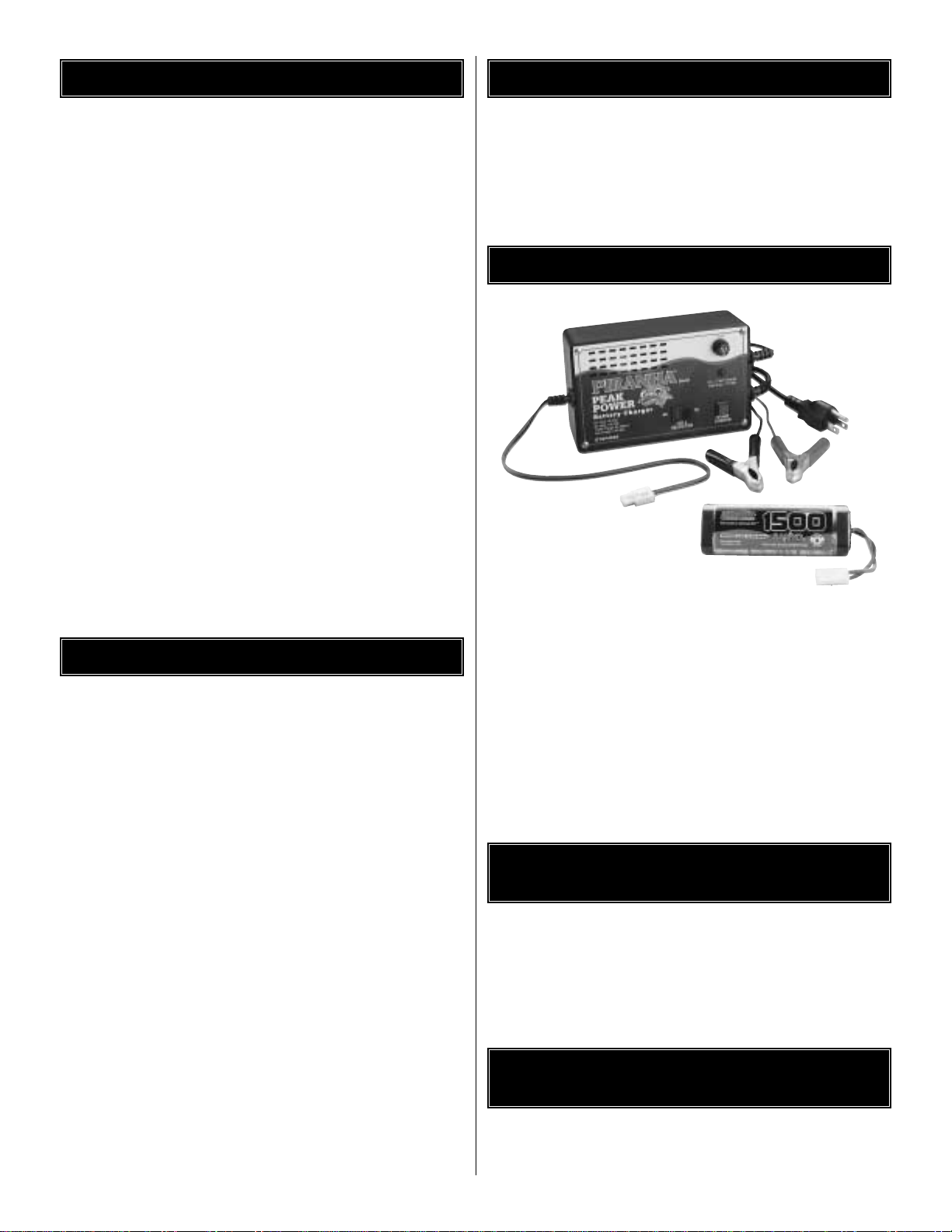
❏2.Charge the 6 or 7 cell battery (not included) on the charger
(not included). See Safety Precautions before charging and
charge the battery according to the instructions that came
with your charger.
❏ 3. Install the transmitter antenna by screwing it into the
hole on the top of the transmitter. Give a light tug on the
antenna to be sure it is seated properly.
❏ 4. Slide open the battery door on the bottom of the
transmitter.Install eight (8) “AA”batteries into the transmitter
in the configuration molded into the plastic on the battery
holder.Re-install the battery door.
❏5.Turn on the transmitter using the on/off switch (see step 3).
The red light on the transmitter should light up. If there is no
light on, turn the transmitter off and check to ensure that the
batteries are making contact with the metal contacts in the
battery holder. Make sure the batteries are installed correctly.
T urn the transmitter on and check f or the red light.If the red light
appears, turn off the transmitter. If the red light blinks, the
batteries are low and should be replaced.
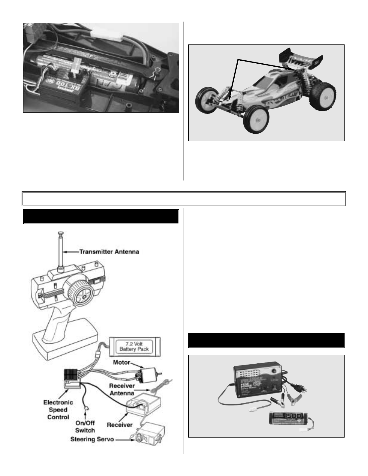
❏ 6. Straighten the receiver antenna. Route the receiver
antenna through the holes in the chassis as shown above.
Locate the antenna tube and thread the receiver antenna
through the antenna tube. The antenna will be longer than
the antenna tube. DO NOT CUT OR COIL THE ANTENNA
WIRE. Press fit the antenna tube into the hole in the chassis.
Tip: Run the antenna wire through your fingers to
straighten out the kinks before running through the
antenna tube. Also, applying a small amount of soap
and water to the antenna wire will help lubricate the wire
for threading into the antenna tube. Use a piece of tape to
hold the excess antenna wire to the antenna tube.
❏ 7. Remove the body pin from the battery strap post and
remove the battery strap from the Evader BX.
4
FINISHING THE EVADER BX RTR VERSION (DTXD22**)
Route the antenna
through the chassis
and then through
the tube.
Remove the pin and lift
the strap to install/remove
the battery pack.
Install the strap
between the bumps.
Page 5
❏ 8.Install the charged 6 or 7 cell battery into the battery slot.
Re-install the battery strap onto the Evader BX. Note that
there is a channel in the chassis for the battery strap to
rest in. Re-install the body clip into the battery strap post.
❏ 9.The transmitter features a adjustable steering rate knob
labeled “D/R” on the top of the transmitter. Tur ning it fully
clockwise will give you the greatest amount of steering
travel.Turning it counterclockwise will reduce the amount of
steering travel.If you are just learning to drive R/C you may
want to use less steering travel at first.
❏ 10. Decal the body as desired and install on the chassis.
Install the wing into the holes in the rear shock tower. Note:
If the wing fits loosely, bend the end of the wires a bit.
❏ 11. Proceed to page 8 for Running and Maintenance Tips.
5
❏
1. Install the “AA” batter ies in the transmitter.
❏
2. Install and extend the transmitter antenna.
❏
3. Connect the steering servo and electronic speed control
to the receiver.
❏
4. Uncoil and extend the receiver antenna.
❏
5. Hook up the charged 6 or 7 cell battery to the electronic
speed control.
❏
6. Adjust the servo trims of the transmitter to the
center (neutral) position.
❏
7. Switch on the transmitter.
❏
8.Switch on the electronic speed control.
❏
9.Operate the steering and throttle control. Make sure the
steering servo arm and motor move in proportion to the
movement of the steering wheel and throttle trigger.
❏
10.Switch off the receiver, then the transmitter.
❏
1.Charge the 6 or 7 cell battery (not included) on your charger
(not included). See Safety Precautions before charging.
CHARGE Y OUR B A TTERY
PREPARING THE RADIO SYSTEM
FINISHING THE EVADER BX PRE-BUILT VERSION (DTXC0022)
Body Clips
Page 6

6
❏
1. Locate and remove from the parts bag two (2) steering
servo mounts, one (1) servo arm (determine which servo arm
is required for your radio system), one (1) 4-40 ball stud, one
(1) foam washer, two (2) 3x8mm S/T pan head screws and
two (2) 4-40 x 5/16"flat head machined screws To ensure
that you are using the right size screw , match the scre w to the
picture on the hardware chart.
❏
2. Attach the servo mounts to the servo using two (2)
3x8mm S/T pan head screws.
❏
3. Install the 4-40 ball stud into the flat side of the steering
servo arm in the upper hole.With the steering servo centered
as described in “Preparing the Radio System”, install the
correct steering servo arm onto the ser vo splines as shown
above. (Note: If the steering servo is not properly centered,
the steering could be off). Re-install the servo horn screw,
securing the horn onto the ser vo.
❏
4. Remove the two (2) 4-40 x 3/4
"
socket head machined
screws from the upper plate and rotate the front suspension of
the buggy forward.(Note: Be careful that you do not loosen
any of the steering assembly parts during this process).
❏
5. Install the steering servo into the mounting slot. Line up
the holes in the servo mounts with the two holes in the chassis.
(Note: There are two different mounting holes in the servo
mounts. Use the appropriate holes for your servo). Install the
two (2) 4-40 x 5/16"flat head machined screws through the
bottom of the chassis into the servo mounts. Attach the
steering link ball cup onto the 4-40 ball stud on the servo.
STEERING SERVO INSTALLATION
Page 7

7
❏
6.Install the servo brace onto the chassis using the two (2)
4-40 x 3/8"socket head machined screws and two (2)
4-40 x 3/4"socket head cap screws. Re-install the two (2)
4-40 x 3/4"socket head cap screws into the upper plate.
❏
1. Install the receiver onto the chassis as shown. Remove
the protective backing from one side of the included 1/4" thick
piece of foam tape and install it onto the chassis. Then
remove the other piece of protective backing and install the
receiver onto the foam tape.
❏
2. Route the receiver antenna through the holes in the
chassis as shown above .Locate the antenna tube and thread
the receiver antenna through the antenna tube.The antenna
will be longer than the antenna tube.DO NOT CUT OR COIL
THE ANTENNA WIRE. Press fit the antenna tube into the
hole in the chassis. Tip: Run the antenna wire through
your fingers to straighten out the kinks before running
through the antenna tube. Applying a small amount of
soap and water to the antenna wire will help lubricate the
wire for threading into the antenna tube. Use a piece of
tape to hold the excess antenna wire to the antenna tube.
❏
3. Remove the body pin from the battery strap post and
remove the battery strap from the Evader BX.
❏ 4
.Install the charged 6 or 7 cell battery into the battery slot.
Re-install the battery strap onto the Evader BX. Note that
there is a channel in the chassis for the battery strap to
rest in. Re-install the body clip into the battery strap post.
❏4.Decal the body as desired and install on the chassis.
Install the wing into the holes in the rear shock tower. Note:
If the wing fits loosely, bend the end of the wires a bit.
RECEIVER INSTALLATION
Body Clips
Remove the pin and lift
the strap to install/remove
the battery pack.
Install the strap
between the bumps.
Route the antenna
through the chassis
and then through
the tube.
Page 8

8
Note: The set-up portion of the Sprint ESC occurs in the
first 2 seconds when the speed control is turned on.
❏
1. Set the throttle trim of the transmitter at neutral.
❏
2.Turn the transmitter on.
❏
3.Turn the electronic speed control on.
❏
4. Squeeze the throttle trigger all of the way and hold it for
2 seconds.
❏
5. Push the throttle trigger to full reverse and hold it for
2 seconds.
❏
6. Return the throttle trigger to neutral. The green LED
should turn on after a few seconds.
❏
7.The speed control will hold this setting until it is reset.
❏
8. If the speed control did not set-up, repeat the steps.
BALL DIFFERENTIAL BREAK-IN
The ball differential has been adjusted at the factory for proper
“break-in”. Do not tighten the differential before the buggy has
been properly broken-in or you can damage the differential.
After running the buggy for 2 or 3 battery packs, the ball
differential will require readjustment.This is the “normal” breakin period for the ball differential.Y ou will hear a “squealing”sound
when accelerating from a stop and the buggy will accelerate
slower. This indicates that the differential is properly broken-in
and now requires adjustment. Do not run the buggy again until
the differential is properly readjusted as follows.
Adjusting the differential is quick and easy. Access the
adjusting screw by disconnecting the rear camber link (using
pliers) at the right rear wheel.Rotate the wheel and universal
joint out of the way.
While holding the left rear tire, tighten the adjusting screw by
inserting the included L-wrench into the cap screw on the
right side of the ball differential. The screw should be
tightened until it is “just snug.” Caution: Do not over tighten
the adjusting screw or you will damage the diff erential.Next,
loosen the screw 1/8 of a turn.
Reinstall the universal shaft back into the differential and
reattach the camber link. The ball differential may need
occasional adjustment to maintain performance.
BEFORE EACH RUN
❏
1. Check to make sure that all screws are tight and there
are not any screws missing.
❏
2.Check to mak e sure that the transmitter batteries are not low.
❏
3. Check to make sure that all of the moving parts of the
Evader move freely and do not bind.
❏
4.Check f or broken or damaged parts.Replace any broken
or damaged parts before running the Evader BX. Running of
the Evader BX with broken or damaged parts could result in
damage to other parts.
❏
5. Check to make sure that the receiver and speed control
are still properly secured to the chassis.
❏
6.Check to make sure that all wires are properly connected.
AFTER EACH RUN
❏
1. Clean any large globs of dir t or debris from the chassis
and moving parts.
❏
2. Disconnect and remove the battery from the Evader.
❏
3. Check for any broken or damaged parts.This way parts
may be replaced before the next run.
AFTER EVERY 10 RUNS
❏
1.
The servo saver is factory set. During normal
maintenance, check its operation by g r asping the servo arm
and linkage and turning one of the front tires left and right.
If the wheels turn without moving the linkages and servo
arm then the unit is operating properly. If the linkage and
servo arm move, loosen the knurled adjustment nut on the
left side servo saver shaft. If the servo saver becomes
clogged with dirt, it may not work properly which could
cause servo or linkage damage. The servo saver needs to
be disassembled, cleaned and readjusted. To safely adjust
the servo saver, loosen the knurled aluminum collar on the
left side steering post completely. Then reinstall 1½ turns
onto the post. Retest the servo saver as described above.
Adjust the servo saver tighter or looser if needed.
❏
2.Check to make sure that the bearings are free of dirt and
debris and roll smoothly.
❏
3.Check the shocks f or oil leakage.If the shocks hav e leaked
any shock fluid out, you should properly refill the shocks for best
performance.Inspect the shock shafts for deep scratches.
❏
4. Check the motor brushes for wear.If the motor brushes
are severely worn or discolored they should be replaced.
❏
5. Check for buildup and wear on the bushings of the
motor. If the bushings are dirty, use DuraTrax Power Shot to
clean them. If the bushings are worn, replace the motor.
❏
6. Make sure the servo saver is free moving and does not
bind.This will help prevent stripping of the servo during running.
❏
7. Check for smooth gear mesh between the spur and
pinion gear.
RUNNING AND MAINTENANCE TIPS
NOTE:The Sprint electronic speed control is pre-set at the
factory. The following instructions should be followed if
the pre-set needs to be changed. During nor mal running,
the speed control should be switched “on” and not given
input from the transmitter for 2 seconds.This bypasses the
set-up stage of the ESC.
ELECTRONIC SPEED CONTROL SET UP
Camber Link
1. Remove the Camber Link.
2. Rotate the Universal Joint out of the way.
3. Adjust the diff screw using the L–Wrench.
Universal Joint
L–Wrench
Page 9

99
Steering Bellcrank Assembly
1. Insert two of the brass bushings (105) into the chassis.Note:The brass
bushings may need to be slightly tapped into place. The bushings
must be fully seated in the chassis.
2. Insert the short aluminum bellcrank post (99) into the right brass bushing
in the chassis.
3. Install ball studs (81) into the right bellcrank (46) in the holes shown.
4. Insert a plastic bushing (47) into each end of the right steering bellcrank.
Again, make sure the bushings are fully seated.
5. Slide the assembled right bellcrank onto the short aluminum bellcrank
post (99).
6. Install ball studs (81) into the lower left bellcrank (44) in the holes shown.
7. Insert the threaded aluminum servo sav er hub (101) into the bottom of the
lower left steering bellcrank (44). Note:The aluminum servo saver hub is
designed to key into the bottom of the lower left steering bellcrank.
Make sure that the hex in the hub fully seats in the bellcrank.
8. Install a ball stud (81) into the upper left steer ing bellcrank (45).
9. Slide the upper left steering bellcrank (45) onto the ser vo saver hub (101).
The upper and lower left steering bellcranks are designed to key together.
10.Place the servo saver spring (98) on top of the two left steering bellcranks.
11. Secure the left bellcrank assembly together with the aluminum servo
saver spring adjuster (102). Note: The servo saver spring adjuster is
machined on one side for the servo saver spring to fit into.Make sure
this side goes down against the servo saver spring.The servo saver
spring will need to be properly adjusted once the entire steering
bellcrank assembly had been installed on to the Evader BX.
12. Insert a plastic bushing (48) into each end of the left steering bellcrank
assembly. Again, make sure the bushings are fully seated.
13. Install the long aluminum bellcrank post (100) into the left brass
bushing in the chassis.
14. Slide the assembled left bellcrank assembly onto the bellcrank post.
15. Attach the left and right bellcranks together with the one piece molded
link (43).
The following information has been provided to help maintain and tune the Evader BX.
ASSEMBLY GUIDE
Front Knuckle Arm, Hub Carrier, Axle
1. Attach the front hub carriers (28) to the front suspension
arms (38) using the (95) front outer hinge pins.
2. Install the front axles (91) into the knuckle arms (24L or 25R).
3. Install two spacers onto each kingpin.
4. Insert the knuckle arms (24L or 25R) into the front hub carriers
(28) then secure them in place with the kingpins (94). Note:The
spacers go on the top of the hub carriers (28).
5. Secure the kingpins (94) in place using 2.5mm e-clips (S).
6. Install 3mm set screws into the axles (91) to secure them to
the kingpins (94).
94
D
50
38
Y
28
2
67
81
24L
M
B
95
S
91
S
81
67
43
46
99
47
105
100
48
102
81
98
45
44
101
105
Page 10

1010
Servo, Servo Plate, Upper Plate
1. Attach the servo mounting lugs (6) to the front of the servo
mounts on the servo using two 3x8 self tapping screws (L).
2. Install a ball stud (81) into the steer ing servo horn (8).
Insert the ball stud into the hole fur thest from the center.
3. Install the steering servo horn onto the servo. Note:
Make sure the transmitter, steering servo and servo
horn are properly centered before securing the servo
horn to the servo.
4. Secure the servo to the chassis with two 4-40x5/16" (B)
flat head screws.
5. Attach the servo brace (56) to the chassis by installing two
4-40x3/8" (C) socket head screws into the two rear holes.
6. Connect the servo to the steering bellcrank assembly
using the adjustable steering servo link (5 & 90).
7. Install two brass bushings (105) into the underside of the
upper plate (52). Note: The brass bushings may need to
be slightly tapped into place. The bushings must be
fully seated into the upper plate.
8. Install the upper plate (52) onto the ser vo plate (56) and
steering bellcrank assembly. Make sure the steering
bellcrank posts insert into the bushings in the upper plate.
Secure the upper plate with four 4-40x3/4" (E) socket head
screws and two 4-40x5/16" (B) flat head screws (b ulkhead).
Rear Shock Tower, Rear Transmission Plate , Rear Bulkhead, Rear Suspension Arm.
1. Attach the rear chassis plate (41) to the chassis using four 4-40x3/8" (C) socket head screws.
2. Attach the rear suspension ar ms (36L or 37R) to the rear chassis plate (41) using the inner rear hinge pins (97).
3. Secure the inner rear hinge pins (97) in place using two 2.5mm e-clips (S).
4. Install the rear shock tower (40) and rear b ulkhead (42) onto the chassis using f our 4-40x1/2" (D) screws .Note: Make sure the
screws pass through the shock tower,chassis and into the rear bulkhead.
5.Install two ball studs (81) into the appropriate holes in the rear bulkhead. Note:The stock setting is the lower inner holes.
Make sure that the ball studs are in the same hole location on both sides.
E
C
B
52
56
5
81
90
T
8
L
6
F
36
67
97
41
81
53
40
42
37
1
D
C
S
Page 11

1111
Bulkhead, Bulkhead Brace,
Front Suspension Arm,
Front Shock Tower, Front Bumper
1. Attach the front bulkhead to the chassis using the (103)
hinge pin.
2. Secure the hinge pin in place using a 2mm set screw.
3. Attach and secure the front suspension arms (38) to the
front bulkhead (51) using the (104) front inner hinge pins.
4. Secure the rear of the front inner hinge pin with a 2.5mm
(S) e-clip.
5. Install the front bulkhead brace (50) onto the two front
inner hinge pins.
6. Secure the front bulkhead brace using 2.5mm (S) e-clips.
7. Attach the front shock tower (49) to the front bulkhead
using four 4-40x3/8" (C) socket head screws.
8. Secure the front body mount to the shock tower using two
4-40x3/8" (C) socket head screws.
9. Attach the front bumper (2) to the front bulkhead using four 4-40x5/16" (B) flat head machine screws.
10. Attach the top of the front bulkhead to the upper plate (52) with two 4-40x5/16" (B) flat head machine screws.
Ball Differential
1. Place one of the differential thrust washers (121) onto the 3x25mm cap screw (G).
2. Lubricate the differential thrust washer using silicone grease then install the plastic thrust ball holder (19) and 1/16"
thrust balls (113).
3. Lubr icate the other differential thrush washer (121) and install it on top of the 1/16" thrust balls (113) and holder (19).
4. Inser t the screw and thrust ball assembly into the left outdrive (92).
5. Apply a small amount of silicone grease to one of the differential rings (120) and place it onto the left outdrive. The
grease should hold the differential ring in place.
6. Install a 5x9mm bear ing onto the left outdrive.
7. Install the 3/32" differential balls (112) into the differential gear (18).
8. Install a 5x9mm bear ing into the center of the differential gear and install the gear onto the left outdrive.
9. Install the other differential ring (120) onto the right differential outdrive (93).
10. Insert the differential spring (123), lock nut holder (22) and the 3mm lock nut (M) into the end of the right differential
outdrive (93).
11. Join the left and right differential outdrives together and tighten the 3x25mm cap screw (G) until the differential gear
cannot be turned while both differential outdrives are being held.The differential will require fine tuning once it has been
installed into the car.
3
103
51
104
S
38
67
50
22
49
38
S
O
81
F
C
2
B
5
120
123
3/32" Hex wrench
The diff can be initially adjusted
by tightening the diff bolt until
snug and then back off 1/8 turn.
121
G
113
120
19
112
93
18
109
92
Page 12

1212
Slipper Clutch
1. Install the inner slipper plate (86) onto the top shaft (83). Make sure the notch in the inner slipper plate keys onto the
2x10 spring pin in the top shaft.
2. Place the slipper pad (64) and outer slipper plate (85) onto the top shaft (83).Make sure the slipper pad (64) is properly
centered between the two plates (85 & 86).
3. Install a slipper bushing (86) into the spur gear (16).
4. Slide the spur gear (16) onto the top shaft (83) and secure it to the outer slipper plate (85) using (2) 3x6mm screws (J)
and (2) 3mm lock washers (P).
5. Slide a 3mm flat washer (V) 3mm brass washer (W) and then another 3mm washer (V) onto the top shaft.
6. Install the slipper spr ing (87) 3mm washer (V) then the 3mm lock nut (O). Refer to page 16 for adjusting the slipper.
86
Rear Hub, Rear Axles
1. Install two 5x10mm bearing (108) in both of the rear hubs (26L or 27R).
2. Install a ball stud (81) into the center hole of the rear hubs.
3. Place a 3mm plastic spacer (58) on each side of the rear hubs. Secure the rear hubs (26L or 27R) to the rear suspension
arms (36L or 37R) with the 3mm outer rear hinge pins (107).
4. Secure the outer rear hinge pins (107) with 2.5mm e-clips (S).
5. Install the rear axles (79) through the bear ings in the hubs.
6. Slide a rear axle washer (82) onto the axle then install a 2.5x12mm spring pin (117) into the rear axle.
64
85
16
86
MOTOR
(119)
80
J
P
H
W
87
V
O
74
S
79
81
67
27
58
37
S
82
107
M
117
10858
Page 13

1313
Gearbox
Note:When installing the bearings make sure they are fully seated. If the bearings are not fully seated
the gearbox halves may not properly fit together or may cause binding.
1. Install a 5mm washer (X) onto each end of the top shaft (83)
2. Install a 5x10mm bearing (108) into the upper hole of the left gearbox half (21).
3. Install the top shaft (83) into the 5x10mm bear ing that was just installed into the left gearbox half.
4. Install the 2x10mm spr ing pin (116) into the top shaft
5. Attach the roll pin cover (7) to the left gearbox half.
6. Install a 5x10mm bear ing (108) into each side of the idler gear (17).
7. Install the idler gear shaft (89) into the idler gear bear ings.
8. Install the idler gear into the left gearbox half (21).
9. Install a 12x18mm bear ing (110) into the lower hole in the left gear box half (21).
10. Install the ball differential into the 12x18mm bearing that was just installed into the left gear box half (21).
11. Inser t a 12x18mm (110) and 5x10mm bear ing (108) into the r ight gearbox half.
12. Install the two gearbox halves together. Make sure the two gearbox halves seat together properly.
13. Secure the two halves together with the 4-40x1/2" socket head screw (D).
14. Install the aluminum motor plate (96) on the side of the gearbox and attach it with the (3) 3x25mm socket
head screws (G).
7
21
108
X
116
83
X
20
P
96
89
108
108
17
G
110
P
110
D
Page 14

1414
Shocks
1. Install a 2.5mm e-clip (S) onto the lower groove on the shock shaft (77 or 78).Install the e-clip into the groove closest to
the center of the shaft.
2. Place the shock piston (4) on top of the 2.5mm e-clip.
3. Secure the shock piston (4) in place with a 2.5mm e-clip (S) in the groove towards the end of the shaft.
4. Install a shock o-ring (114) then the plastic spacer (35) then another shock o-ring (114) into the shock seal holder (33).
Secure all of the parts in the shock seal holder using the shock seal cap (34).
5. Install the shock shaft assembly into the shock seal assembly.
6. Fill the shock with fluid then install the shock seal assembly into the shock.
7. While tightening the shock seal assembly down work the shock shaft and piston up and down to help remove any air
and excess oil that may be trapped in the shock.
8. Thread the shock shaft end (31) onto the end of the shock shaft (77 or 78). Note: To hold the shock shaft, use needle
nose plies with a piece of cloth (to protect the shaft).
9. Install the shock ball (106) in the shock end (31).
10. Install the shock spring (70 or 71) onto the shock body (75 or 76).
11. Secure the shock spring in place with the shock retainer (32).
n
35
78 (Rear)
77 (Front)
122
76 (Rear)
4
71 (Rear)
70 (Front)
S
75 (Front)
32
106
31
34
2. Slowly screw the cap
down about half way.
Push the piston part
114
33
way down to slowly
bleed off excess oil.
3. Tighten the cap a little
1. Fill to the top
with oil. Let all air
more and push the pisto
down the rest of the way.
bubbles rise to
the top before
assembly.
4. Finally, tighten the cap
all the way.
With a properly filled shock, the piston can be pushed in completely
and will then rebound about 3/8".
Exercise the shock a few times and listen for air bubbles. If you hear
any squishing, rebuild the shock.
Page 15

15
When tuning the Evader BX make sure that you have equal
length shocks on both sides (left and right), camber rods and
steering rods. Also, make sure to have the shock pre-load
adjusters at the same setting from left to right. They do not
have to be the same front to rear.
CASTER
Caster refers to the angle at which the kingpin is at in relation
to the surface when viewed from the side. 0 degrees of caster
means that the kingpin is straight up and down. The Evader
comes stock with 30 degrees of caster and is not adjustable.
CAMBER
Camber refers to the angle at which the tire and wheel ride in
relation to the ground when viewed from the front or rear.
Negative camber is when the tire and wheel lean inward and
positive camber is when the tire and wheel lean outward.Typically
you want 0 to 2 degrees of negativ e camber .Never put in positive
camber. Make sure that both sides have equal amounts of
camber by keeping the camber turnbuckles equal in length.
FRONT TOE-IN AND TOE-OUT
Toe-in and toe-out refers to the angle at which the tire is at
when viewed from above. Toe-in increases stability under
acceleration . However, toe-in also decreases steering when
entering a corner.Toe-out will increase steering into corners,
but will decrease the overall stability during acceleration.The
front typically is set-up with 0 to -2 degrees of toe-in.
Rear toe-in affects the traction of both the front and rear of
the buggy. Rear toe-in increases the amount of traction in the
rear, but decreases steering. Decreasing rear toe-in will
increase steering, but will give less rear traction.The Evader
comes pre-set with 3 degrees of rear toe-in.
WHEEL BASE
Wheel base is the distance from the center of the front wheel
to the center of the rear wheel. By lengthening the wheel
base of the Evader it increases steering, but decrease rear
traction as a result of increase weight distribution to the front
wheels. Decreasing the wheel base of the Evader will
increase rear traction, but decrease steering.
BATTERY PLACEMENT
The battery placement of the Evader can be adjusted with the
foam spacers which will affect the buggy’s rear traction.
Spacing the battery in the forward position will create less
rear traction. Spacing the battery in the rear position will
create more rear traction.
RIDE HEIGHT
The ride height of the Evader BX effects how it jumps and
handles.The ride height of the Evader BX is adjustable through
the threaded pre-load adjusters on the shock bodies. To
measure the ride height of the Evader, set the buggy up as if
you are ready to run. Push the front of the buggy down all of
the way and release it.When the buggy returns the front ar ms
should be parallel with the surface.The rear r ide height is set
up the same except that the drive shafts are parallel with the
surface. Lowering the front ride height will increase steering
response due to more weight on the front wheels.Lowering the
rear ride height will increase rear traction and reduce steering
response due to more weight on the rear wheels.
CAMBER LINK PLACEMENT
The camber link placement affects the traction and handling
on rough tracks. By using a long mounting position, it will
increase traction but decrease stability. By shortening the link,
it will increase stability, but decrease traction.
t
g
TUNING GUIDE
15
30˚ Caster
2˚ Negative Camber
Front Front Fron
Lon
Middle Short
Adjust
1˚
1˚
1˚ Toe-In
Front wheels pointed towards each other.
Page 16

SLIPPER ADJUSTMENT
The slipper clutch is designed to help prevent gear breakage
during jumping and controls traction. The slipper should not
be over tightened, this could cause damage to the diff erential
gears. The slipper should be set so that it slips for 1-2 feet
from a stop with a fully charged battery.
FRONT SHOCK ADJUSTMENT
Moving the tops of the shocks out will increase steering and
quicker suspension reaction.Moving the tops of the shocks in
will result in slower steering reaction, but will be smoother
over bumps .Mounting the bottoms of the shocks in the inside
hole will give more slow speed steering but will take away
some high speed steering.
REAR SHOCK ADJUSTMENT
Moving the tops of the shocks in will result in more traction in
the corners and will be smoother over the bumps.Moving the
tops of the shocks out will give the buggy more steering and
handle large jumps better.
SHOCK OILS AND SHOCK SPRINGS
Many different combinations can be used between the shock
oils and shock springs. Some basic guidelines when setting
up the Evader are that if the rear end is stiff it will give the
buggy more steering and have less rear traction. Hardening
the front will result in less steering and more rear traction.
(Changing the position of the threaded shock pre-load
adjusters results in ride-height change. It does not change
the spring tension). Thinner shock oil make the shocks react
faster, but makes the buggy less stable and may cause the
buggy to bottom out over large jumps. Thicker shock oil
makes the buggy smoother ov er large jumps and in str aights ,
but less reactive over rough sections. We have filled the
shocks with 20 weight shock oil, which is a good choice for
most driving conditions.
ADJUSTABLE STEERING RATE
Adjust the D/R knob to increase or decrease the steering
travel.When first learning to drive, adjust the dual rate knob
for less steering trav el.As you get to be a better driver, adjust
the dual rate knob for more steering travel.
OTHER PRODUCTS AVAILABLE FROM DURATRAX
IntelliPeak™Pulse Chargers give each battery a full charge, whether it’s a
NiCd or a NiMH pack. Use at home or at the track, to charge, discharge, or
even cycle a pack automatically. 1-year warranty.
DTXP4100 AC/DC Pulse Charger,
DTXP4110 AC/DC Mini Pulse Charger,
DTXP4120 AC/DC Deluxe Pulse Charger,
DTXP4130 AC/DC Digital Pulse Charger
Race economically with the Shark 6-cell 1500mAh sport pack
(DTXC2030)...or go for explosive output current and all-out speed with
Sanyo 1900SCRs (DTXC2130)! Both are assembled and ready to run.
Save by powering your transmitter with rechargeable NiCds! This kit
includes eight "AA" Sanyo®NiCd cells and a 110V AC wall charger.
Connect it to the radio's charge jack, and you can recharge the batteries in
just 2-3 hours — without removing them from the transmitter. DTXP4010
DuraTrax Power Shot™ Motor Spray
Ozone-safe and a must for routine car
maintenance -- quickly removes dirt and
grime. Safe for Lexan®bodies and most
other plastics. DTXC2458
 Loading...