

Page 1

®
™
ASSEMBLY AND OPERATION MANUAL
www.duratrax.com
Page 2

ITEMS
INCLUDED
The following items are included
with your Cliff Climber.
Chassis
Body
Decal Sheet
Transmitter (RTR Only)
Transmitter Antenna (RTR Only)
Transmitter Frequency Flag (RTR Only)
Receiver Antenna Tube
Exploded View/Parts Listing
YOU WILL
NEED
x 8
“AA” BATTERIES
ONYX™ 240 AC/DC DUAL CHARGER
DTXP4240
IF YOU HAVE THE ARR VERSION
YOU WILL ALSO NEED
• A radio system that includes transmitter, receiver and two standard servos. We
recommend the Futaba 2PL radio system (FUTK02**). For even better performance,
two high-torque servos such as Hobbico’s CS-170 (HCAM0316) can be used.
x 2
6-CELL 2/3 “A” CELL 7.2V
1200MAH NIMH STICK
DTXC2194
x 2
BATTERY ADAPTERS
(FOR CHARGING)
DTXC2210
• An electronic speed control capable of use with two 380 size motors and two 7.2-8.4V
batteries. We recommend the DuraTrax ESC-15K (DTXC1280).
• A dual servo output harness such as FUTM4130.
• Polycarbonate-compatible paint of the user’s choice.
2
Page 3
THINGS TO
SPECIFICATION AND
DESCRIPTION CHANGES
STRESS-TECH™ PARTS
GUARANTEE
KNOW
SAFETY PRECAUTIONS
When the safety precautions are followed, the
Cliff Climber will provide years of enjoyment.
Use care and good sense at all times when
operating this radio controlled crawler.
Failure to use this vehicle in a safe, sensible
manner can result in injury or damage to
property. You and you alone must insure that
the instructions are carefully followed and all
safety precautions are obeyed.
• Do not use lithium-polymer batteries with
the stock ESC unless a voltage cut-off
unit is used.
• Water can cause the electronics to short
out and can cause permanent damage.
• Always turn on the transmitter before
turning on the receiver.
• Fully extend the transmitter antenna
before operating your vehicle.
• Before turning on your radio sytem, check
to make sure that no one else is running
on the same frequency.
• Keep out of reach of children. The motors
and ESC may become hot during running.
• Never leave a battery on charge unattended.
• If the battery or the charger become hot
at any time, disconnect the battery from
the charger immediately! Failure to do
so could cause permanent damage to
the charger and battery and may cause
bodily harm.
• Do not allow water or moisture to contact
the charger.
• Do not place the charger on or near a
fl ammable object during use.
• Only use 6-cell or 7-cell “2/3 A” size
batteries in your Cliff Climber.
• Avoid running the Cliff Climber in cold
weather. The plastic and metal parts
can become brittle at low temperatures.
In addition, grease and oil become
thick, causing premature wear and poor
performance.
All pictures, descriptions and specifi cations
found in this instruction manual are
subject to change without notice. DuraTrax
maintains no responsibility for inadvertent
errors in this manual. Visit www.duratrax.
com for the latest updates and information
for your model.
WARRANTY
• DuraTrax® guarantees this kit to be
free from defects in both material and
workmanship at the date of purchase.
DuraTrax will warranty this kit for 90
days after the purchase date. DuraTrax
will repair or replace, at no charge, the
incorrectly made part.
• Make sure you save the receipt or invoice
you were given when you bought your
model! It is your proof of purchase and
we must see it before we can honor the
warranty. Further, DuraTrax reserves the
right to change or modify this warranty
without notice.
• In that DuraTrax has no control over the
fi nal user assembly or material used for
fi nal user assembly, no liability shall be
assumed nor accepted for any damage
resulting from the use by the user of the
fi nal user-assembled product. By the act
of using the user-assembled product, the
user accepts all resulting liability.
To return your Cliff Climber for repairs
covered under warranty, you should send
your truck to:
Hobby Services
3002 N. Apollo Drive, Suite 1
Champaign, Illinois 61822
Attn: Service Department
Phone: (217) 398-0007 9:00 am-5:00 pm
Central Time M-F
E-mail: hobbyservices@hobbico.com
www.hobbyservices.com
If the buyer is not prepared to accept the
liability associated with the use of this
product, the buyer is advised to return
this kit immediately in new and unused
condition to the place of purchase.
We have engineered the Cliff Climber to
take the rough and tumble abuse that makes
R/C fun. We are so confi dent of the quality
and durability of the Stress-Tech plastic
parts that we will replace any Stress-Tech
plastic part you break during the fi rst 12
months you own the crawler. Just send in
the part to us and we will send you a FREE
replacement. Please see the Cliff Climber
parts list for the items covered under the
Stress-Tech guarantee.
To receive your free replacement part
please send the following to the Hobby
Services address listed under the warranty
on the left.
❏ 1. The broken part must be included.
❏ 2. The part number and description of the
broken part.
❏ 3. Copy of your dated invoice or
purchase receipt.
❏ 4. Your name, phone number and
shipping address.
REPAIR SERVICE
Repair service is available anytime.
• After the 90 day warranty, you can still
have your Cliff Climber repaired for a
small charge by the experts at DuraTrax’s
authorized repair facility, Hobby Services.
• To speed up the repair process, please
follow the instructions listed below.
❏ 1. Under most circumstances return
the ENTIRE vehicle. The exception would
be sending in a Stress-Tech part. See the
instruction under the Stress-Tech Guarantee.
❏ 2. Make sure the transmitter is turned off,
and all of the batteries are removed.
❏ 3. Send written instructions which include:
a list of all items returned, a THOROUGH
explanation of the problem, the service
needed and your phone number during the
day. If you expect the repair to be covered
under warranty, be sure to include a proof
of date of purchase (your store receipt or
purchase invoice).
3
Page 4
FINISHING
THE CLIFF CLIMBER RTR
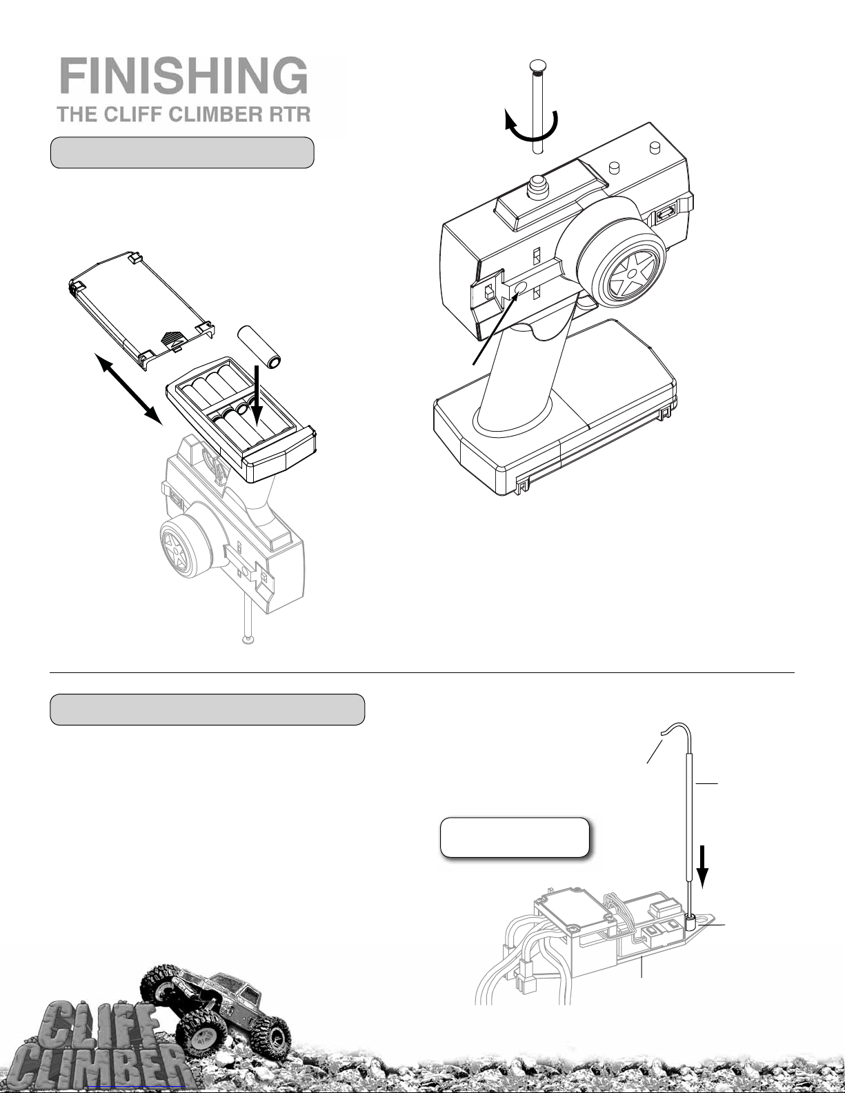
TRANSMITTER PREPARATION
• Slide the batttery tray door off and install
eight “AA” batteries into transmitter,
making sure the polarity is correct.
Battery
Tray Door
+
–
–
+
–
+
–
+
+
+
–
Battery On
• Insert the antenna into the top of the transmitter and gently tighten.
• Turn the transmitter on and check the battery light. If the red light glows
RECEIVER ANTENNA INSTALLATION
• Thread the receiver antenna wire up through the
antenna tube. The antenna will be longer than the
antenna tube.
• Press fi t the antenna tube down into the molded
antenna mount on the battery strap.
• Tip: Run the antenna wire through your fi ngers to
straighten out the kinks before running it through the
antenna tube. Also, applying a small amount of soap
and water to the antenna wire will help lubricate the
wire for threading into the antenna tube.
steadily, the batteries have enough voltage. If the red light blinks, the
batteries are low and should be replaced.
DO NOT CUT THE
ANTENNA WIRE!
X
Receiver
Antenna Wire
Antenna
Tube
Antenna
Tube Mount
Battery Strap
4
Page 5
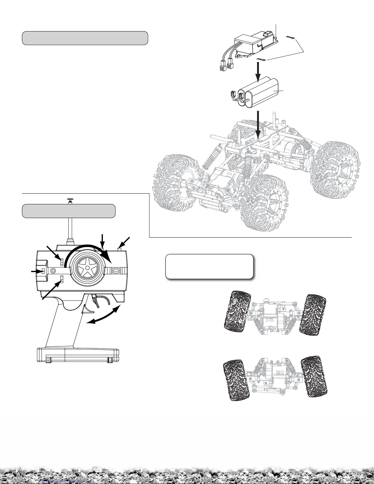
BATTERY INSTALLATION
• Remove the battery clips from the battery strap.
Battery Strap
Battery Clips
• Remove the battery strap.
• Install the 7.2V batteries (not included) into the
chassis as shown.
• Reinstall the battery strap and secure it in place
with the battery clips.
• Check that the ESC is “OFF,” and then plug the
batteries into the ESC.
RADIO SYSTEM CHECK
Steering
Servo
Reverse
Switch
On/Off
Steering
Tr i m
Throttle
Tr i m
CHECK THE RADIO SYSTEM
FOR PROPER FUNCTION
!
BEFORE EACH RUN
7.2V Batteries
Throttle
Servo
Reverse
Switch
Forward
The ESC is an autoset ESC. No programming is required.
• Turn the transmitter on and center the throttle trim.
• Turn the ESC on. Wait 2 seconds while the ESC sets itself up.
• When you pull the throttle trigger back, the red LED will fl ash
and the truck will go forward.
• When you push the throttle trigger forward, the green LED will
fl ash and the truck will go in reverse.
• At neutral, the LEDs will be on constantly.
• If the truck goes in reverse when you pull the throttle trigger,
switch the throttle reveresing switch on your transmitter.
Reverse
5
FRONT
REAR
• Turn the transmitter on. Then turn the ESC on.
• Turn the transmitter wheel to the right—the front
wheels should turn to the right and the rear wheels to
the left. If not, move the steering servo reverse switch.
• When running, adjust the steering trim so the crawler
tracks straight.
Page 6
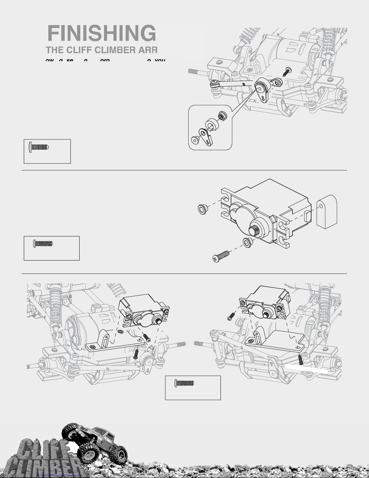
FINISHING
THE CLIFF CLIMBER ARR
The following section is provided to help you with
assembly of the almost-ready-to-run version of the Cliff
Climber. Pay extra attention to the notes and tips for
proper assembly.
• Assemble the front and rear servo saver bushings (45), arms
(44), rings (43), and adapters (42) as shown.
3x10mm
Screw
9
• Secure the assembled servo savers onto steering linkage
rods D (9) with 3x10mm screws.
...x1
3x10mm Screw
• Install a fl anged bushing (11) into the upper eye on each side
of the servos as shown.
• Using a 3x10mm S/T screw, secure a servo mounting block (41)
to the side of the servos with the output splines as shown.
...x1
3x10mm S/TScrew
45
11
42
43
44
3x10mm S/T Screw
Caution: Be sure to use the correct servo
spline adapter (42) for your servo. They
are marked for easy identifi cation:
F ➙ Futaba
H ➙ Hitec
J ➙ Airtronics/Sanwa
41
11
40
3x10mm S/T Screw
Front Rear
3x10mm S/T Screw
3x10mm S/T Screw
40
3x10mm S/T Screw
...x4
3x10mm S/TScrew
• Secure the side of the servos without the mounting blocks to
the servo tray mounts (40) using 3x10mm S/T screws.
• Secure the side of the servos with the installed mounting
blocks (41) to the bottom of the servo tray mounts (40) with
3x10mm S/T screws.
6
Page 7
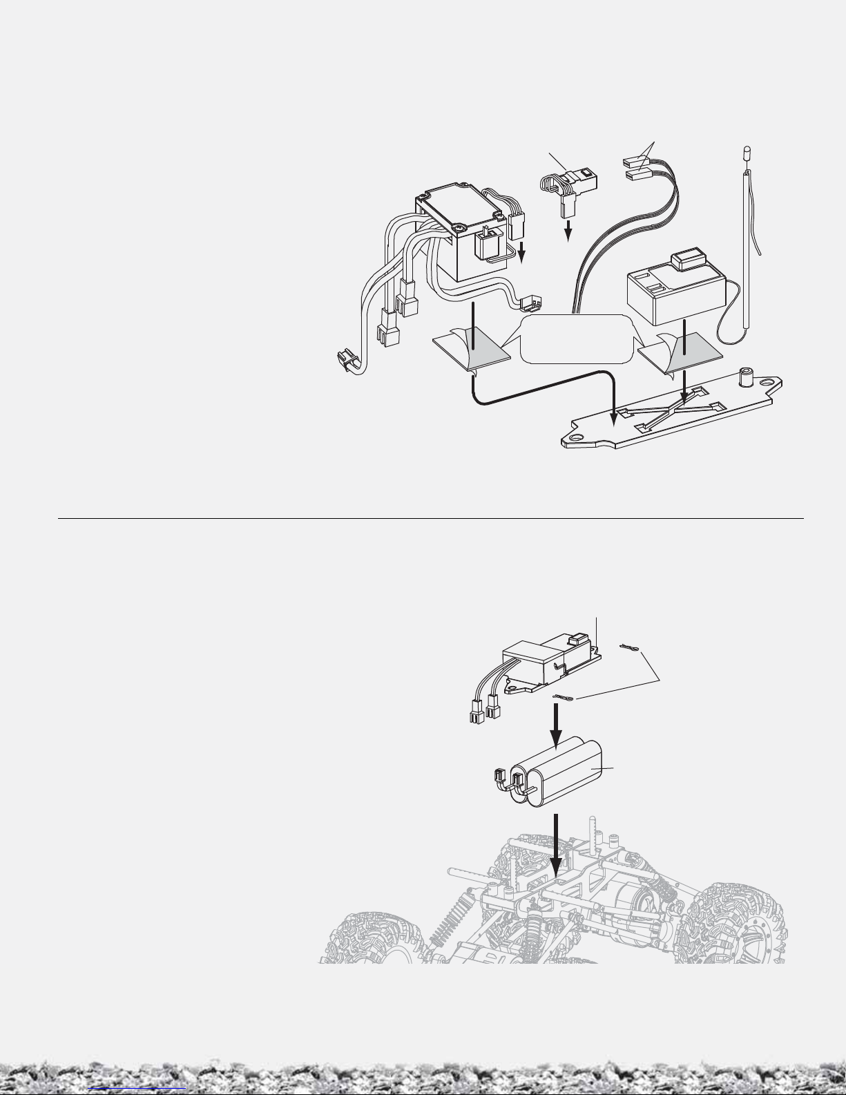
• Secure the ESC and receiver to the top
of the battery strap with double-sided
mounting tape (DTXR1215).
• Connect the ESC and receiver being
used, following the instructions that
came with the ESC and radio system.
Normally the ESC plugs into channel 2
on the receiver.
• Thread the receiver antenna wire up
through the antenna tube. The antenna
will be longer than the antenna tube.
• Connect both front and rear servo
leads into the larger plug on the servo
Y-harness (not included).
• Connect the Y-harness into channel 1
on the receiver. Mount the Y-harness
with double face tape (the location will
vary depending on the length of the
servo leads) to secure it.
ESC
Y-Harness
Ch2
Double-Sided
Ch1
Tape
Steering Servo
Leads
CH2
CH1
RX
• Remove the battery clips from the battery strap.
• Remove the battery strap.
• Install the 7.2V batteries (not included) into the
chassis as shown.
• Reinstall the battery strap and secure it in place
with the body clips.
• Check that the ESC is “OFF,” and then plug the
batteries into the ESC.
Battery Strap
Battery Clips
7.2V Batteries
7
Page 8
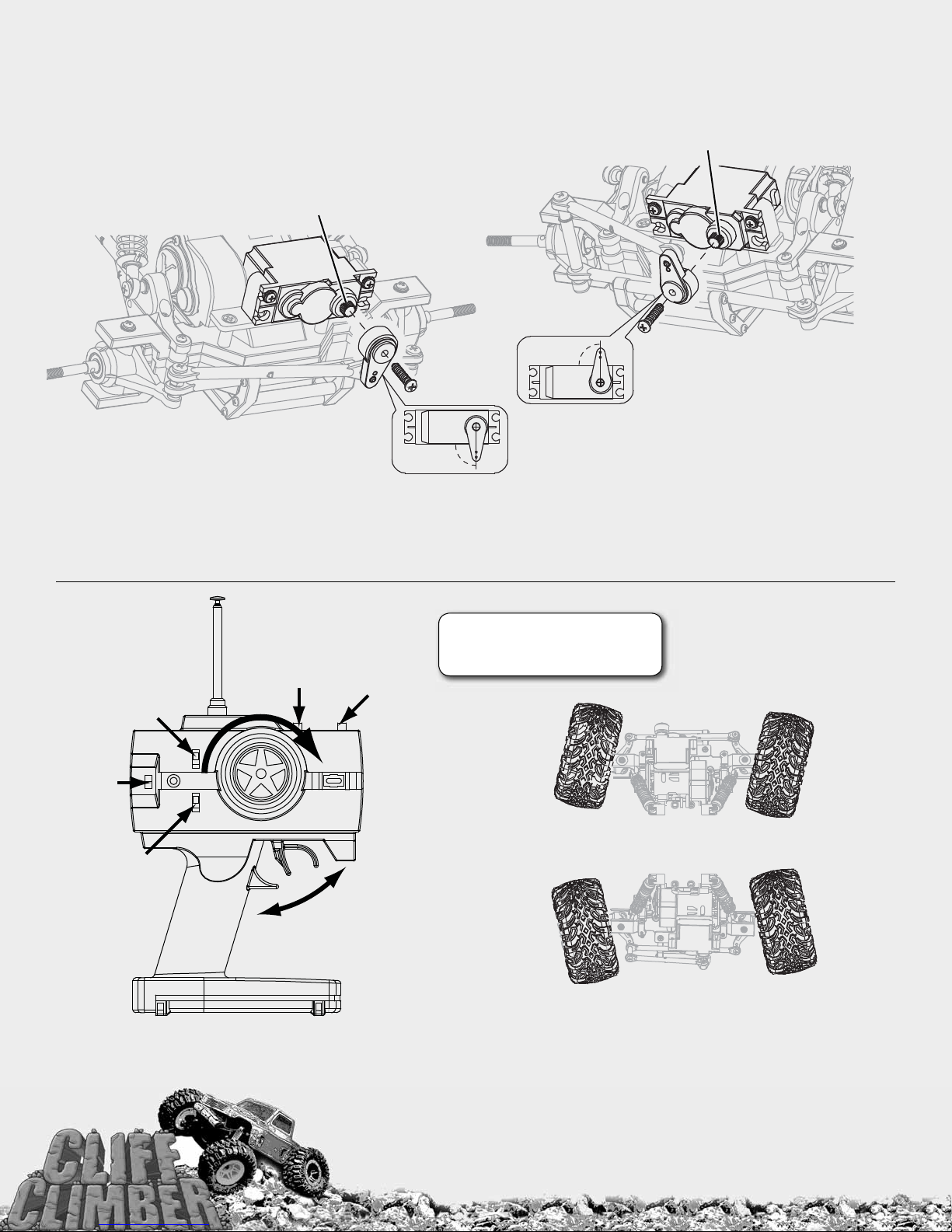
• Turn on the radio system and center the front and rear servos per the
radio system instructions.
• NOTE: You may want to unplug the motors from the ESC until you
completely set up the ESC and radio system. This will prevent a potential
“runaway” when centering the servos and attaching the linkages.
SPLINE
SPLINE
90°
Rear
Front
• Install the front servo horn onto the servo
output spline pointing down at a 90° angle.
• Secure the servo savers to the servos with the
servo horn screw that came with the servo.
Steering
Servo
Reverse
Switch
On/Off
Throttle
Servo
Reverse
Switch
Steering
Tr i m
Forward
Throttle
Tr i m
Reverse
• Install the rear servo horn onto the servo output
90°
CHECK THE RADIO SYSTEM
FOR PROPER FUNCTION
!
BEFORE EACH RUN
spline pointing up at a 90° angle.
• Secure the servo savers to the servos with the
servo horn screw that came with the servo.
FRONT
REAR
• Turn the transmitter on. Then turn the ESC on.
• Set up the ESC according to the instructions that came with your ESC.
• Turn the transmitter wheel to the right—the front wheels should turn to the right
and the rear wheels to the left. If not, move the steering servo reverse switch.
• When running, adjust the steering trim so the crawler tracks straight.
8
Page 9
The Cliff Climber ARR body comes clear. Below are a few tips to follow when painting your Cliff Climber.
CAUTION:
• Always paint in a well-ventilated area.
• Never paint near an open fl ame.
• Wash the inside of the body out with dish soap and water. Make sure the body is thoroughly rinsed out.
• Use a quality masking tape or Hobbico® Liquid Mask to mask the inside of the body off.
• If using masking tape, make sure it is properly sealed down.
• If using Hobbico Liquid Mask, make sure to use multiple coats. Make sure not to put the liquid mask on too thick
or too thin. 2-3 medium coats work best.
• Use a new hobby blade when cutting the masking tape or liquid mask.
• Paint the inside of the body using a quality Lexan compatible paint. Spray dark colors fi rst and always back light
colors with white or silver.
• Remove the clear protective fi lm from the outside of the body.
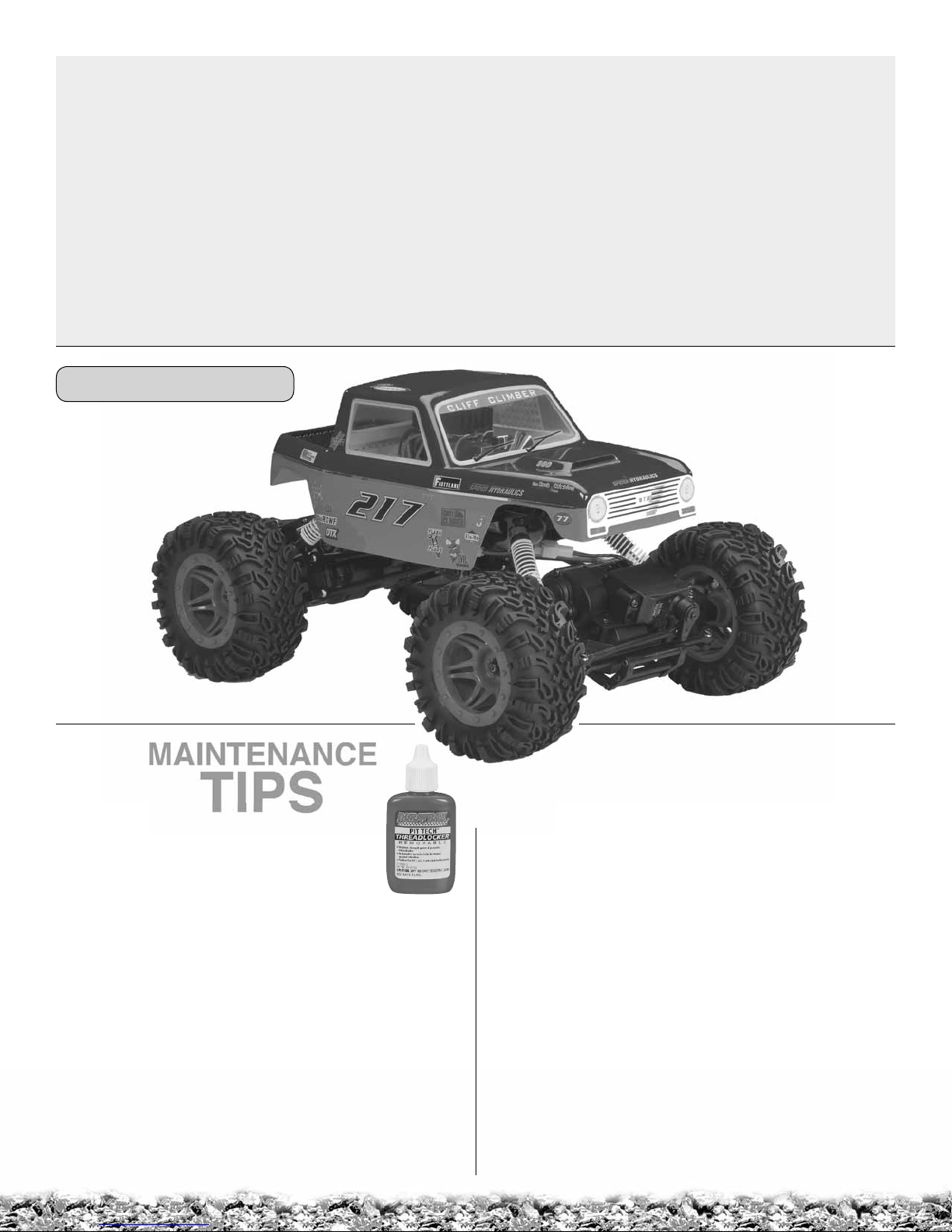
• Decal the body to your liking. Use the
BODY INSTALLATION
photos on the box as a reference.
• Install the body onto the chassis using
four body clips.
MAINTENANCE
TIPS
Before Each Run
• Check to make sure that all screws are tight.
Always use threadlock (DTXR2010) on screws
going into metal.
• Before running, always check the condition of your radio
system batteries and replace/recharge them if necessary.
• Check to make sure that all of the Cliff Climber’s moving
parts move freely and do not bind.
• Before running, turn on the radio and make sure the servos
move easily and in the proper direction.
• Check for broken or damaged parts. Replace any that
are found before running the Cliff Climber. Running the
Cliff Climber with broken or damaged parts could result in
damage to the rest of the truck.
• Check to make sure that all wires are properly connected.
• Check that the ESC and receiver are properly secured.
After Each Run
• Clean any large globs of dirt or debris from the chassis and
moving parts.
• Check for any broken or damaged parts. This way parts
may be replaced before the next run.
• Disconnect and remove the batteries from the Cliff Climber.
After Every 10 Runs
• Check to make sure that the bushings are free of dirt and
debris, and roll smoothly.
• Check the shocks for oil leakage. Inspect the shaft and
O-rings for wear and damage. Replace if necessary. (A
shock shaft with scratches you can feel with a fi ngernail
should be replaced.)
• Check the tires to make sure they are still properly glued
to the wheels.
9
Page 10
TUNING
d
l
s
PINION GEAR
GUIDE
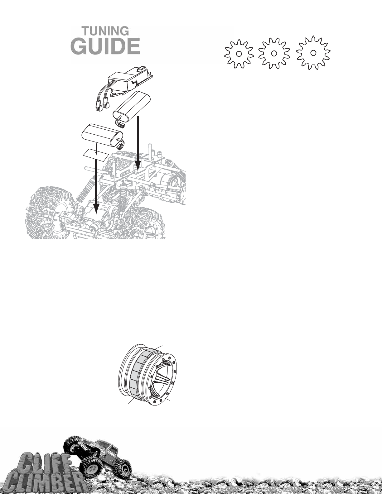
BATTERY PLACEMENT
7.2V Battery
7.2V Battery
Hook & Loop
Material
Front
Battery placement is an easy way to improve the Cliff Climber’s
crawling capabilities. Take one of the batteries and install it on
top of the front steering servo. Lay the other battery down in
the Cliff Climber chassis. By placing the battery over the front
steering servo, you lower the center of gravity of the vehicle
and you place additional weight over the front wheels for
additional traction and better weight bias. There are a couple
of different ways to install the battery on the front steering
servo. The fi rst is by purchasing the DuraTrax optional servo
battery mount (DTXC6279). If you don’t currently have the
servo battery mount, you can use hook and loop material on
the battery and the servo.
WEIGHT
Another quick and easy way
to improve your Cliff Climber’s
crawling capabilities is to add
weight to the front rims. This
can easily be done by installing
a strip of stick-on lead weights
(available at most hobby
shops) all the way around
each of the front wheels.
Tip: Make sure the weight is
evenly placed all the way around the rim to help prevent the
wheels from being severely out of balance. This will increase
Wrap weights
evenly.
the weight over the
front wheels, increasing
traction and stability.
Segmented
Stick-On
Lead Weight
Whee
More
Torque
11 Tooth 12 Tooth
(Stock)
The Cliff Climber comes stock with a 12 tooth pinion. Optional
11 tooth (DTXC8347) and 13 tooth (DTXC8349) pinions are
also available. If you fi nd that you need a little more torque,
go down to 11 tooth pinions. If you are looking for a little more
speed from the Cliff Climber, go to 13 tooth pinions. Always use
the same size pinion on both motors. Make sure you set your
gear mesh properly if you change the pinions. You want a small
amount of play between the pinion and the gear. Too tight, and
you will damage the gears and possibly the motor and ESC. Too
loose, and you can strip the gears.
STEERING
Another way to improve the Cliff Climber’s crawling ability
is to install high torque servos. This will allow you to use
the strength of the steering servo to help maneuver around
obstacles. Another good upgrade is aluminum servo horns
(DTXM5010) on the steering servos. This will eliminate any
give in the steering allowing you to use the strength of the
servos. Caution: By removing the servo savers from the
steering servos, you increase the chances of the servo
getting damaged during use. We recommend you only use
an aluminum servo horn with metal geared servos.
For better clearance over rocks you can remove the front
and rear bumpers. Caution! This will expose your steering
linkage to impact and could cause damage to your servos.
SHOCKS
The Cliff Climber comes stock with 30 weight shock oil
installed in the shocks. We found this to be a good general
setup. Changing the shock oil can change how the Cliff
Climber crawls. This is something you will have to experiment
with, depending on what type of surface you are crawling on.
There are also optional shock springs available for the
Cliff Climber. Again, this is something that you will have to
experiment with to see what works best for you.
DTXC9112 Yellow (Medium, stock)
DTXC9156 Green (Firm)
DTXC9157 Blue (Extra Firm)
BUILDING A ROCK CLIMBER COURSE
The options for building an R/C crawling course for your Cliff
Climber are only limited by your imagination and access to
supplies. It can be as simple as stacking some books, boxes
or other general household items in your living room. You can
use rocks, wood or just anything you can stack outside to
crawl with your Cliff Climber. There are also several different
threads in the rccrawler.com forum that describe how to
build more complex crawling courses.
10
13 Tooth
More
Spee
Page 11

ce
MAINTENANCE
GUIDE
The following section is provided to help you with maintenance
following section is provided to help you with maintenan
and repairs to your Cliff Climber. Pay extra attention to the
notes and tips for proper assembly.
3x6mm
1 2
3x6mm
Bushing
..........2
3x6mm Bushing
Bushing
x2
x2
3
x2
4
10x15mm
Bushing
5x11mm
Bushing
..........2
5x11mm Bushing
..........2
10x15mm Bushing
5x11mm
Bushing
10x15mm
Bushing
x2
..........2
3x10mm Screw
3x10mm Screw
x2
3x10mm Screw
11
Page 12

5
..........2
3x10mm Set Screw
Shaft
E-Clip
..........1
4mm E-Clip
......1
2.5mm Shaft
..........2
5x11mm Bushing
6
3x10mm
Set Screw
4mm E-Clip
2.5mm Shaft
5x11mm
Bushing
3x10mm Set Screw
5x11mm
Bushing
x2
7
..........2
3x6mm Bushing
x2
x2
3x6mm Bushing
12
Page 13

8
2mm E-Clip
..........2
2mm E-Clip
9
2mm E-Clip
10
..........2
2.6x8mm Screw
..........2
3x10mm Screw
..........2
2.6mm Lock Nut
..........1
3x10mm S/T Screw
x2
3x10mm Screw
2.6x8mm Screw
x2
3x10mm S/T Screw
3x10mm Screw
2.6x8mm Screw
x2
2.6mm Lock Nut
2.6mm Lock Nut
13
Page 14

11
..........1
3x3mm Set Screw
12
2.6x20mm Screw
..........2
2.6mm Washer
3.5mm
3mm Set Screw
Apply
Threadlock
x2
.....2
x2
2.6mm Washer
2.6x20mm Screw
2.6mm Washer
Apply
Threadlock
2.6x20mm Screw
14
Page 15

The gear mesh on the Cliff Climber is adjustable. Make sure to set the
gear mesh properly to avoid damage to the gears. The gear mesh should
be set so that there is a slight amount of play between the pinion and the
gear it meshes with. Be careful not to set the mesh too loose or too tight.
13
14
x2
Check for proper
gear mesh
3x10mm S/T Screw
3x10mm S/T Screw
x2
3x10mm S/T Screw
15
2.6x10mm S/T Screw
2.6x10mm S/T Screw
2.6x10mm S/T Screw
x2
.......2
........6
2.6x10mm S/T Screw
2.6x10mm S/T Screw
2.6x10mm S/T Screw
2.6x10mm S/T Screw
15
Page 16

16
..........3
2.6x10mm S/T Screw
17
..........4
2.6x8mm Screw
2.6x8mm Screw
2.6x10mm S/T Screw
2.6x10mm
S/T Screw
x2
2.6x10mm S/T Screw
2.6x8mm Screw
2.6x8mm Screw
2.6x8mm Screw
16
Page 17

18
3x8mm Screw
..........4
3x8mm Screw
3x8mm Screw
3x8mm Screw
3x8mm Screw
19
..........4
5.8mm Ball
5.8mm Ball
5.8mm Ball
A
5.8mm Ball
B
5.8mm Ball
A
B
17
A
102mm
B
103.5mm
x4
Page 18

20
Note the direction
of the flange.
B
3x28mm Screw
3x28mm Screw
B
B
Note the direction
of the flange.
21
3x15mm Screw
Note the direction
of the flange.
3x15mm Screw
A
........4
3x28mm Screw
3x15mm Screw
B
B
3x28mm Screw
A
B
B
A
..........4
B
A
3x15mm Screw
3x15mm Screw
18
Page 19

22
Note the direction
of the flange
Note the direction
of the flange
....8
3x15mm Screw
3x15mm
Screw
3x15mm Screw
3x15mm
Screw
3x15mm Screw
Note the direction
of the flange
3x15mm Screw
3x15mm
Screw
3x15mm
Screw
Note the direction
of the flange
3x15mm Screw
19
Page 20

2.6x20mm
Shoulder Screw
23
2.6x20mm
Shoulder Screw
The shock mounts should be
able to rotate. Do not
overtighten the
mounting screws.
......4
2.6x20mm
Shoulder Screw
2.6x20mm Shoulder Screw
2.6x20mm Shoulder Screw
1.5mm E-Clip
24
..........2
1.5mm E-Clip
Oil the shock shaft and O-rings
before installing the shock shaft
to prevent damage to the O-ring
during assembly.
1.5mm E-Clip
Oil
Oil
Oil
x2
20
Page 21

25
Slowly move the shaft up
and down to remove air
bubbles. Push the shock
shaft up when installing
the shock cap. Note: Make
sure the shock piston
does not come out of
the oil when pushed up.
26
Oil
x4
27
2x10mm Screw
2x10mm Screw
Insert the
screw into
the shock
mount as
shown.
x4
..........4
2x10mm Screw
2x10mm
Screw
21
Page 22

28
5.8mm Ball
5.8mm Ball
5.8mm Ball
29
3x15mm Screw
.......2
5.8mm
Ball
..........4
5.8mm Ball
3x15mm Screw
Note the direction
of the flange.
3x15mm Screw
Note the direction
of the flange.
x2
22
Page 23

30
3x30mm
Screw
3x30mm
Screw
3x30mm Screw
Do not
overtighten.
3x30mm Screw
Do not
overtighten.
3x30mm Screw
..........4
3mm Lock Nut
31
..........3
2.6x8mm Screw
3mm Lock Nut
..........4
2.6x8mm Screw
3mm Lock Nut
3mm Lock Nut
3mm Lock Nut
x2
2.6x8mm Screw
2.6x8mm
Screw
x2
23
Page 24

32
5.8mm Ball
C
C
C
121.21mm
..........4
5.8mm Ball
5.8mm Ball
33
3x18mm Screw
...1
x2
5.8mm Ball
D
5.8mm Ball
D
87.8mm
D
x2
Front
..........1
3x10mm Screw
..........1
3mm Lock Nut
3x18mm Screw
3x10mm Screw
3mm Lock Nut
24
Page 25

Rear
34
..........1
3x10mm Screw
3x15mm Screw
3x18mm Screw
35
3x18mm Screw
......1
3x10mm Screw
..1
3x15mm Screw
36
..........1
3x10mm Screw
Front
x2
3x10mm Screw
25
Page 26

37
..........1
3x10mm Screw
Rear
38
..........1
3x10mm S/T Screw
3x10mm Screw
3x10mm S/T Screw
39
..........2
3x10mm S/T Screw
Install the servo
as shown.
3x10mm S/T Screw
3x10mm S/T Screw
Front
26
Page 27

Install the servo
as shown.
40
..........2
3x10mm S/T Screw
41
..........1
3x12mm S/T Screw
*Check for proper screw
size depending on the
servo used. The screw
for the RTR is shown.
3x10mm
S/T Screw
Rear
3x10mm
S/T Screw
Front
42
3x12mm S/T Screw
*Check for proper screw
size depending on the
servo used. The screw
for the RTR is shown.
Rear
..........1
3x12mm S/T Screw
Do not
overtighten
3x12mm S/T Screw
27
Page 28

43
3x10mm Screw
3x10mm Screw
3x10mm Screw
........4
3x10mm Screw
3x10mm Screw
44
45
Red to
batteries
Yellow
to motor
CH1
CH2
Double-Sided
Tape
To servo leads
Yellow
to motor
28
Page 29

46
47
Now’s a great time
to add weight to the
front wheels.
4mm Lock Nut
4mm
Washer
48
49
4mm Lock Nut
4mm
Washer
CA
Glue
CA
Glue
2.5mm Shaft
Caution: Don’t overflow the glue over the
tire surface.
Note the direction of the tires before gluing.
..........4
4mm Lock Nut
..........4
4mm Washer
.......4
2.5mm Shaft
2.5mm Shaft
29
Page 30

Hop-Ups Available for the Cliff Climber
Axle Tube/Gearbox
Graphite Pattern
DTXC6167
Blue Aluminum Turnbuckle (4)
Suspension Link A
DTXC9491
Blue Aluminum Turnbuckle (2)
Blue Aluminum
Knuckle Arm (2)
Suspension Link A
Bent Blue Alum Turnbuckle (4)
DTXC9489
Suspension Link C
DTXC9493
Suspension Link D
Blue Aluminum Turnbuckle (2)
DTXC9494
Other Accessories Available From DuraTrax
DTXC8230
Suspension Link B
Blue Aluminum Turnbuckle (4)
DTXC9492
7.2V 1400mAh Battery
Tire Glue
DTXR2000, Thin
DTXR2002, Med
DTXC2185
Long Nose Pliers
DTXR0300
Ultimate Driver Set
Onyx 240 Charger
DTXP4240
Battery Adapter
DTXC2210
DTXR0183
For more optional parts and accessories,
contact your hobby dealer or www.duratrax.com
30
Lead Weight
GPMQ4485
Page 31

ROCK CRAWLING
REFERENCES
For more tips and helpful information about the Cliff Climber
and R/C Crawling, go to www.rccrawler.com.
For information on rules and specifi cations for
R/C competions, go to www.usrcca.com.
31
Page 32

Entire Contents Copyright © 2008 DTXZ1123 for DTXD18** v1.0
 Loading...