

Duratrax CHEVY CAMARO ZL1 Owner's Manual

N
YY
RR
G
3
110
13
32
13
2
2

Accessories
Pit-Tech™ Deluxe Car Stands
Pit Mats
Handy workstation features a rotating upper
plate with molded rubber insert grips. Base
includes an extra-large parts tray.
DTXC2370
Blue
DTXC2371
Orange
DTXC2372
Purple
DTXC2373
Green
The 5 x 5 in (63.5 x 63.5 mm) size is ideal for
small parts and hardware. The 29 x 19 in
(736.6 x 482.6 mm) has room for your vehicle,
heli or small plane, too. Both are made of
durable, solvent- and fuel-resistant rubber.
DTXP2045
5 x 5 in Pit Mat (63.5 x 63.5 mm)
DTXP2050
29 x 19 Pit Mat (736.6 x 482.6 mm)
3
3
This device complies with part 15 of the FCC rules. Operation is subject to the following two conditions.
(1) This device may not cause harmful interference.
(2) This device must accept any interference received, including interference that may cause undesired operation.
NOTE: THE MANUFACTURER IS NOT RESPONSIBLE FOR ANY RADIO OR TV INTERFERENCE CAUSED BY UNAUTHORIZED MODIFICATIONS
TO THIS EQUIPMENT. SUCH MODIFICATIONS COULD VOID THE USER’S AUTHORITY TO OPERATE THE EQUIPMENT.
FCC REQUIREMENT
CE COMPLIANCE INFORMATION FOR THE EUROPEAN UNION
Instructions for Disposal of Waste Equipment by Private Users in the European Union: This symbol on the product or its packaging indicates this
product must not be disposed of with other household waste. Instead, it is the user’s responsibility to dispose of their waste equipment by handing it over
to a designated collection point for the recycling of waste electrical and electronic equipment. The separate collection and recycling of your waste
equipment at the time of disposal will help to conserve natural resources and ensure that it is recycled in a manner that protects human health and the
environment. For more information about where you can drop off your waste equipment for recycling, please contact your local city office, your household
waste disposal service or location where you purchased the product.
Declaration of Conformity:
Product: Duratrax T240F 2.4GHz 2-Channel Tx and R240 3-Channel Rx
Item number: T240F, Equipment class: 2
The objects of the declaration described here are in conformiity with the requirements of the
specifications listed below, following the provisions of the European 2006/95/EC Low Voltage
Directive:
IEC 60950-1:2005(2nd Edition) + Am1:2009/EN 60950-1:2006 + A11:2009 + A1:2010 + A12:2011
The objects of the declaration described here are in conformity with the requirements of the
specifications listed below, following the provisions of the European R&TTE directive 1995/5/EC:
Radio: ETSI EN 300 328 V1.7.1 (2006-10)
EMC: ETSI EN 301 489-1 V1.8.1 (2008-04, Clause 9.2 and 9.3)
ETSI EN 301 489-17 V2.1.1 (2009-05)
Duratrax
c/o Hobbico, Inc.
2904 Research Road
Champaign, IL USA 61826
The associated regulatory agencies of the following
countries recognize the noted certifications to this
product as authorized for sale and use.
UK DE DK BG SE FI GR
EE LV LT PL CZ SK HU
RO SI AT IT ES PT IE
NL LU MT CY
0682
Included radio system not fully compliant with French regulations.
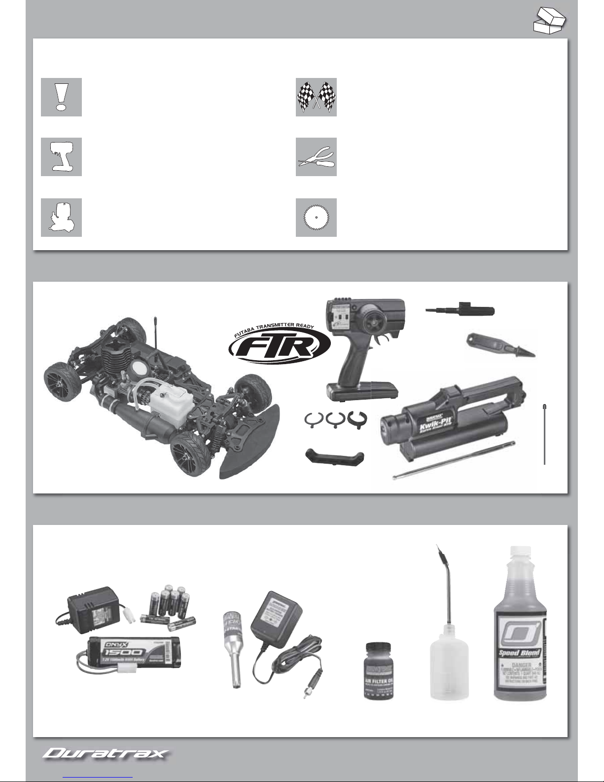
CONTENTS
Chassis
Super Start
Duratrax T240F
2.4 GHz Transmitter
™
Engine Stop Tool
Antenna
Tube
Shock Clips
x4 x4 x4
Rear Hinge Pin Mount
REQUIRES
“AA” (x8)
7.2V 6-Cell Battery Pack & Charger
(DTXP4615)
Glow Starter & Charger
(DTXP3000)
Air Filter Oil
(DTXC2465)
Fuel Bottle
DTXP0150
Fuel
(ODOP4520)
TABLE OF CONTENTS
Bind Tool
4
4
SAFETY PRECAUTIONS AND WARRANTY ....... 5 TUNING GUIDE ............................................. 10
GETTING READY TO DRIVE ............................. 6 ASSEMBLY GUIDE ........................................ 13
BREAK-IN PROCEDURE .................................8 REPLACEMENT PARTS ................................27
5
5
SPECIFICATIONS & DESCRIPTION CHANGES
ALL
information found in this manual is subject to change without notice. Visit Duratrax.com for the latest updates and information on your model.
Duratrax maintains no responsibility for inadvertent errors in this manual.
SAFETY PRECAUTIONS
To prevent injury and damage to property, follow these safety precautions when
operating any radio control vehicle.
Keep all spectators a safe distance away from the vehicle.
ALWAYS turn the transmitter on before the receiver.
NEVER touch any part of the engine or exhaust as they can become very hot.
ALWAYS keep model engine fuel out of the reach of children and follow
precautions on the container.
NEVER smoke and avoid ignition sources when using model engine fuel.
Model engine fuel is poisonous and fl ammable. Keep away from open fl ame.
NEVER run your model indoors. Fuel powered vehicles create harmful fumes.
Use a mat or towel when working on your model to protect your work surface.
Do NOT run your radio control vehicle in cold weather as plastic parts may
become brittle.
LIMITED WARRANTY
Duratrax guarantees this kit to be free from
defects in materials or workmanship for 90
days (3 years for the engine) after the date of
purchase. Duratrax will repair or replace at no
charge any incorrectly made part.
Your receipt or invoice at time of purchase
is your proof of purchase and is required for
Duratrax to honor any warranty. Duratrax
reserves the right to change or modify this
warranty without notice.
For warranty repairs, contact or send to:
Hobby Services
3002 N. Apollo Drive Suite 1
Champaign, IL 61822
ATTN: Service Department
Phone: (217) 398-0007
9:00 am – 5:00 pm Central Time M-F
E-mail: hobbyservices@hobbico.com
www.hobbyservices.com
IF
the buyer is not prepared to accept the
liability associated with the use of this product,
buyer is advised to return kit immediately
in new and unused condition to the place of
purchase.
STRESS-TECH PARTS GUARANTEE
Stress-Tech parts are guaranteed for 12 months from the date of
purchase. Check the parts list for items covered under the Stress-Tech
guarantee. Should a Stress-Tech part break during the fi rst 12 months
after purchase, return the part to Hobby Services and we will send you
a
FREE
replacement.
To receive your
FREE
replacement Stress-Tech part, include the
following and return to Hobby Services at the address above:
1. Broken part
2. Part number and description of the broken part
3. COPY of your dated purchase invoice or receipt
4. Name, phone number and shipping address
TM
REPAIR SERVICE
Hobby Services offers repair services after the limited warranty or 12 month
Stress-Tech parts replacement for a minimal charge.
Follow these instructions for your repair request:
1. Most circumstances require the return of the ENTIRE vehicle. STRESS-TECH
requires ONLY the broken part to be returned following the instructions above.
2. Turn off the transmitter and remove the batteries.
3. Empty fuel tank on nitro vehicles.
4. Include written instructions listing ALL items being returned with a THOROUGH
description of the problem, service needed and your DAYTIME phone number.
IF you expect the repair to be covered under the limited warranty, include
copy of receipt or invoice with date of purchase.
5. Send to Hobby Services at the address above. When shipping your item(s)
to us, we recommend that you insure them and use a company that offers
tracking service (such as UPS or Federal Express).
We will carefully inspect your item and notify you of our fi ndings. You will be
advised of your options for return, repair, or replacement. Please note that items
sent back unrepaired will carry a return shipping and service charge.
Hobby Services accepts Visa®, MasterCard®, or you can send a check. We can
return the item C.O.D., but additional charges will apply.

6
6
6
6
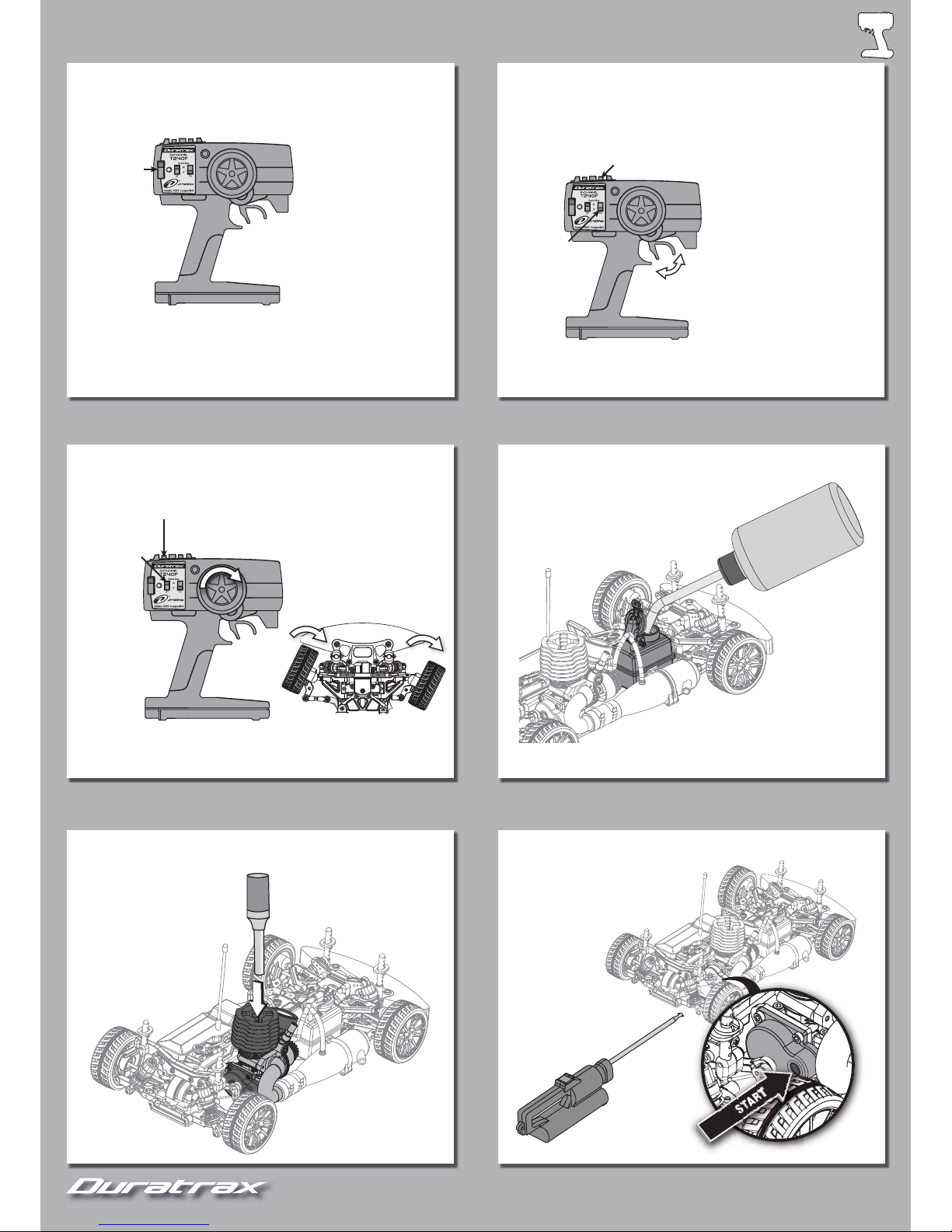
GETTING READY TO DRIVE
Follow these steps to get the radio, super start, and Camaro ready for use.
7.2V NiMH
1. CHARGE THE SUPER
START BATTERY*
2. PREPARE THE SUPER START
+
+
+
+
–
–
–
+
–
3. INSTALL TRANSMITTER
BATTERIES
4. INSTALL RECEIVER
BATTERIES
Do not cut antenna wire!
s
Apply air filter oil (DTXC2465) onto the foam element, squeezing
the element until it is completely coated with the oil.
s
TIP! Placing the element in a plastic bag will help keep your
hands clean.
s
Remove any excess oil with a paper towel.
5. INSTALL ANTENNA TUBE 6. OIL AIR FILTER
*Charger and battery not included.
7
7
Check radio operation
before each run!
On/Off
If you ever need to rebind the receiver, turn on the system
and press the bind button on the receiver using the included
binding tool until the L.E.D. turns solid green.
2.4 GHz
Forward
Brake
Check radio operation
before each run!
Throttle Trim
Throttle
Reverse
Switch
2.4 GHz
7
7
7. POWER UP TRANSMITTER 8. CHECK THROTTLE
Check radio operation
before each run!
Steering Trim
Steering Servo
Reverse Switch
2.4 GHz
9. CHECK STEERING 10. FUEL THE CAR
See page 8 for starting and
enigne break-in details.
11. ATTACH GLOW STARTER 12. START THE ENGINE
8
8
BREAK-IN PROCEDURE
When starting, hold the throttle slightly open. If the engine is diffi cult to turn over, loosen glow plug 1/2-turn before starting engine (this allows
some compression to escape while allowing the engine to start). Once engine starts tighten the glow plug.
IMPORTANT! FLOODED ENGINE:
IMPORTANT! FLOODED ENGINE: If the Super Start still is having problems turning the engine over, it is fl ooded (too much fuel inside the engine).
1. Remove glow plug and turn vehicle upside down, pointing away from you.
2. Run Super Start for 5-6 seconds (clearing engine of fuel).
3. Replace glow plug.
4. Repeat starting engine steps.
Initial engine break in will be accomplished with the fi rst 5 tanks of fuel. (Full break-in may take up to 15 tanks.)
Initial engine break in will be accomplished with the fi rst 5 tanks of fuel. (Full break-in may take up to 15 tanks.)
1. During break-in, run with the body off to keep the engine cool.
2. Keep air fi lter on at all times.
3. Run on smooth, hard surface.
4. Make sure you have extra glow plugs. Break-in puts stress on the glow plug
and it may need to be replaced.
TANK 1
TANK 1
Run very rich allowing fuel to carry as much oil as possible to lubricate internal engine parts.
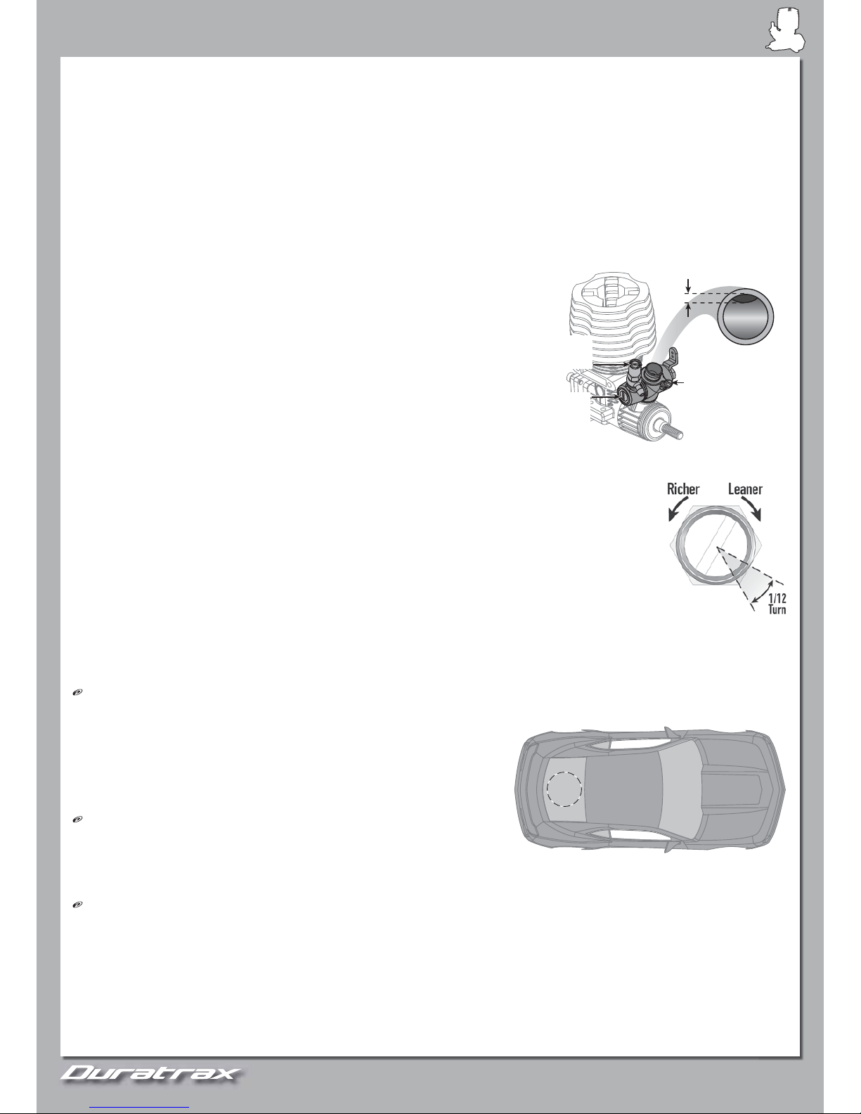
1. High Speed Needle Valve: Check this setting before running. Close the high speed
needle by rotating it clockwise until you just feel resistance, then open to 3 full turns out
(counterclockwise).
2. Run at medium speeds, slowly accelerating and decelerating.
NOTE:
NOTE: It is normal for the
two speed NOT to shift during this tank.
3. If engine does not stay running consistently, increase idle speed by turning the idle stop screw clockwise.
4. DO NOT allow the tank to run out of fuel during break-in.
5. Stop engine by placing the engine tool into the exhaust outlet. Allow it to cool approximately 10 – 15 minutes.
TANKS 2-4
TANKS 2-4
1. For each additional tank, lean high speed needle 1/12 turn from the previous tank’s setting.
2.
Stop engine, allowing it to cool approximately 10 – 15 minutes, between each tank.
TANK 5
TANK 5
1. Lean high speed needle an additional 1/12 turn from Tank 4 setting.
2. The engine should now be very close to fi nal tune and be broken in and ready to be performance tuned.
TUNING TIPS (Adjust only after the engine is fully broken in.)
TUNING TIPS (Adjust only after the engine is fully broken in.)
IMPORTANT!
IMPORTANT!
Always run the engine for 1-2 minutes to warm up temperature before tuning! Only use “small” adjustments (1/12 turn at a time) and test
the results.
High Speed Needle
High Speed Needle::
Controls the fuel/air mixture at high throttle settings. A properly tuned engine will accelerate smoothly and exhaust a
small amount of smoke. The goal is to tune the engine to make good power without overheating. Engine temperature should stay around
250° F (132° C) using a temperature gauge (Duratrax Flashpoint™, DTXP3100).
Note:
Note:
This temperature is a “guideline” only. Your engine may run slightly warmer or cooler
depending on conditions; fuel, track, and how you drive.
On hot days, additional cooling may be needed. Cut a 60mm hole in the rear window to
allow more airfl ow through the body.
Low Speed Needle
Low Speed Needle::
Controls fuel mixture at low throttle settings (idle). To check this
setting, keep the throttle at idle and pinch the fuel line close to the carburetor. A
correct setting will increase the engine speed after 2-3 seconds and then lose speed.
• If it slows too quickly, the mixture is too lean. Open the low speed needle (counterclockwise).
• If it takes longer than 4 seconds to slow down, the mixture is too rich. Close the low speed needle (clockwise).
Idle Stop Screw:
Idle Stop Screw: Adjust this screw to set the idle speed so the wheels do not rotate when you lift the vehicle off of the ground. When looking
into the carburetor, the barrel should be about 1mm from fully closed.
CARE AND MAINTENANCE
CARE AND MAINTENANCE
1. Keep engine clean and free of dirt.
2. Do not over lean engine.
3. Run all of the fuel out of the engine before storing.
4.
Use after run oil and work it into the engine by turning the fl ywheel before storing
.
5. Do not use a fuel with a nitromethane content over 30%.
~1mm
Idle stop
screw
High
speed
needle
Low
speed
needle
60mm
8
8
9
9
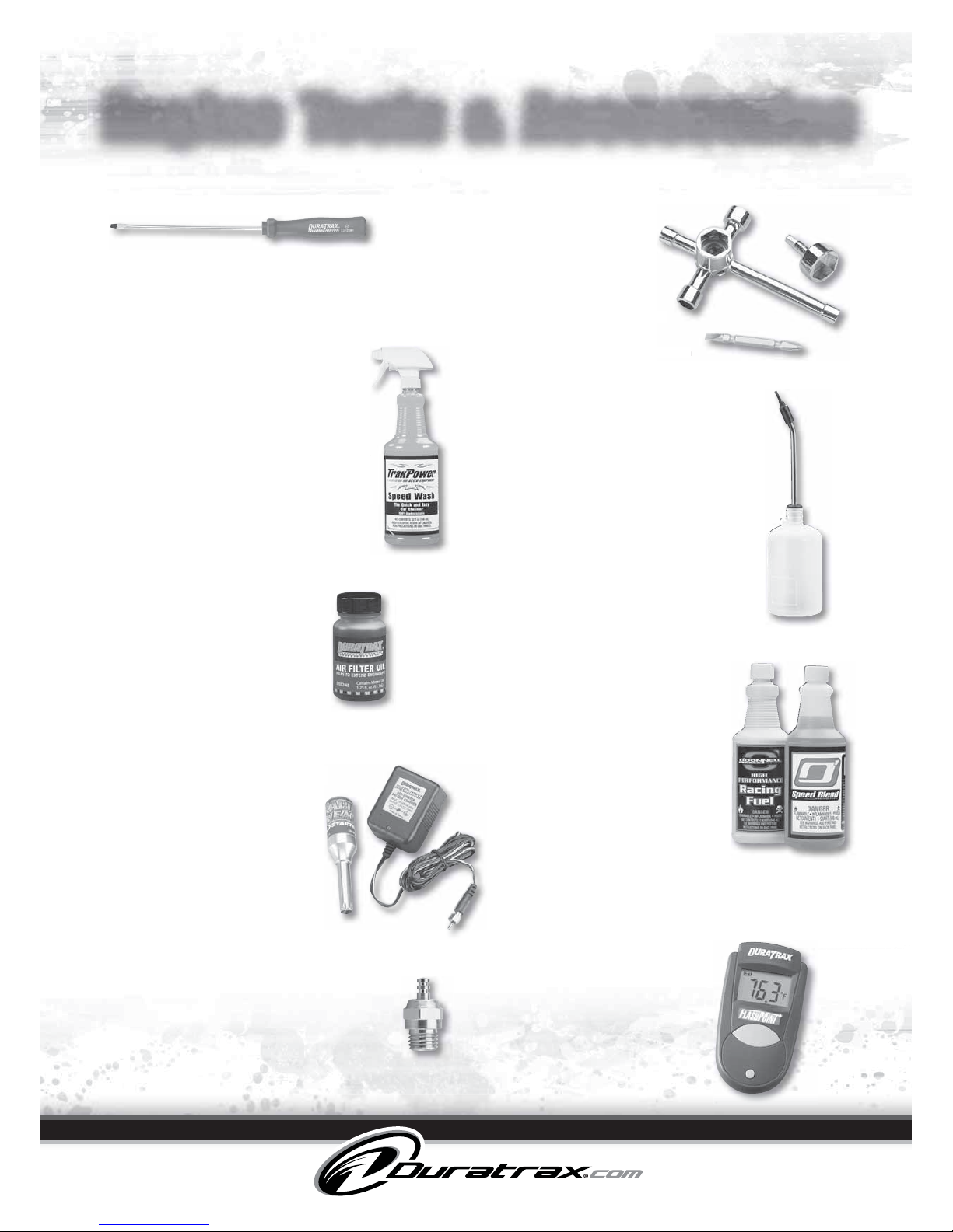
Engine Tools & Accessories
Engine Tuning Screwdriver
TrakPower
™
Speed Wash
Nitro Cleaner
Kwik-Pit
™
Fuel Bottles
Rapid Heat
™
Glo-Starter
FlashPoint
™
Infrared
Temperature Gauge
Deluxe Car Wrenches
O’Donnell Racing Fuel
®
Air Filter Oil
Standard slot-head screwdriver has a 120 mm
hardened steel shaft with 3.2 mm wide magnetized
tip and rubberized, hexagonal handle.
DTXR0185
Applies with or without water and is safe
for titanium, aluminum, fiberglass, clear
coat, stainless steel, chrome, rubber,
plastic, vinyl and leather. 32 fl oz (946 mL).
TKPC8001
A squeeze on the clear plastic body
lets you control fuel flow. The 5 in
(63.5 mm) long aluminum spout
features a curved tip for no-spill refills
and a tip cap to prevent leaks. For
glow fuel only.
DTXP0125
250 cc (8.5 fl oz) Fuel Bottle
DTXP0150
500 cc (17.0 fl oz) Fuel Bottle
Twist-on for a secure connection
to heat your glow plug. Twist
the other way for easy removal.
Includes NiCd and AC charger.
DTXP3000
Just point and press for
fast, accurate, no-touch
temperature readings of
engines, motors, batteries
and more. Works in seconds
and turns off automatically
after 15 seconds of inactivity.
DTXP3100
Hand-assembled with heat resistant coils.
Carbon Speed is medium-hot for informal
racing and sport use. Gold Racing Plug is for
higher nitro fuels and competitive driving.
DTXG3003
Carbon Speed Plug
DTXG3005
Gold Racing Plug
Deluxe includes 6
socket head sizes
and stores up to 4
glow plugs. Ultimate
adds a slotted/Phillips
screwdriver bit and
19 mm socket for 1/8 car
wheel nuts.
DTXR1170
Deluxe Car Wrench
DTXR1175
Ultimate Car Wrench
Speed Blend improves fuel
economy and pushes engine
performance to the absolute
peak. Race Blend simplifies
tuning and reduces engine heat
and internal wear.
ODOP3320
20% Racing Fuel Quart
ODOP3325
25% Racing Fuel Quart
ODOP3330
30% Racing Fuel Quart
ODOP4520
20% Speed Blend Quart
ODOP4525
25% Speed Blend Quart
ODOP4530
30% Speed Blend Quart
Treats foam air filter elements
to increase filtering capacity
and extend engine life. Handy
1.75 fl oz (51.7 mL) bottle fits
easily into a tool box or tote.
DTXC2465
.
r
rench
Glow Plugs
10
10
TUNING GUIDE
As a starting point, make sure your car has equal lengths on shocks, camber links and steering rods on both sides (left
and right). Front and rear do not need to be equal.
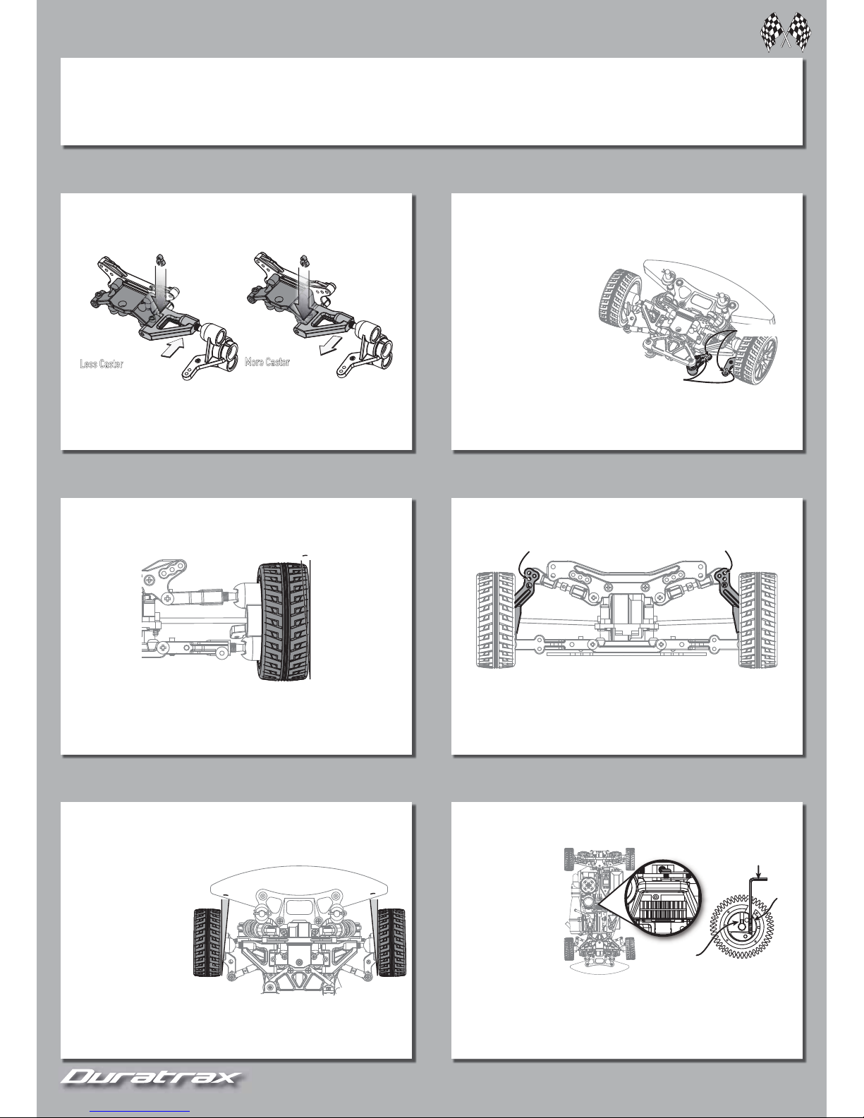
Upper Arm Spacer
Less Caster
= Arm forward
More Caster
= Arm back
Upper Arm Spacer
CASTER
Angle of the front knuckles in relation to the ground when
viewed from the side.
• Increased off power steering
when entering a corner.
• Straight line stability.
• Vehicle more responsive.
• Decreases on power steering
when entering a corner.
• Turns feel smoother.
More Ackerman
Less Ackerman
ACKERMAN
The difference in turning angle between the inside wheel
and outside wheel in a turn.
Less Ackerman
Less Ackerman =
Inside wheel turns more equal to the outside wheel.
Move steering rod forward on the knuckle or back on the bellcranks.
Less aggressive steering, smoother cornering.
Mo re Ackerman
Mo re Ackerman =
Inside wheel
turns increasing more than the
outside wheel. Move steering
rod back on the knuckle or
forward on bellcranks.
More aggressive steering,
vehicle turns more abruptly.
0°
-2°
CAMBER
Angle of the tire and wheel in relation to the ground when
viewed from the front.
Negative Camber
Negative Camber =
Tire and wheel lean inward (Typically 0° to -2°)
• Improved traction while corning.
• Adds overall stability.
Positive Camber
Positive Camber =
Tire and wheel lean outward (This is NOT recommended)
Highest roll center Lowest roll center
ROLL CENTER
Point at which the vehicle rolls laterally when cornering.
Raising Roll Center:
Raising Roll Center: Raise rear camber rod mounting location on the hub.
Increases rear on power traction and decreases rear traction during braking.
Lowering Roll Center:
Lowering Roll Center: Lower rear camber rod mounting location on the hub.
Decreases rear traction on power, reduces corner entry steering and
increases corner exit steering.
Toe-In
-
2°
-
2°
0°
0°
FRONT TOE-IN AND TOE-OUT
Direction the wheels point in relationship with each other,
when viewed from above.
Toe-Out
Toe-Out:: Fronts of the wheels point away from each other.
• Decreased stability when accelerating and increased steering when
entering a corner.
To e-In:
To e-In: Fronts of the wheels
point toward each other.
(Typically 0 to -2°)
• Increased stability when
accelerating. Decreased
steering when entering a
corner.
FRONT CUT AWAY VIEW
1.5mm hex wrench
Do not adjust
this screw!
Adjustmen
t
Screw
2-SPEED SHIFT POINT
Proper shift point helps keeps the engine within its optimum
RPM range.
Shifts too soon
Shifts too soon
(Vehicle will lose acceleration):: Turn the screw in, making
the vehicle shift later and engine rev higher before shifting.
Shifts too late
Shifts too late
(Vehicle will not hit top speed): Turn the screw out, making
the vehicle shift sooner and engine rev less before shifting.
THE ENGINE MUST BE
COMPLETELY BROKEN IN
AND UP TO OPERATING
TEMPERATURE BEFORE
MAKING SHIFT POINT
CHANGES.
IF YOU NEED TO MAKE A
CHANGE, STOP THE ENGINE!
10
10
11
11
CHASSIS MAINTENANCE TIPS
Check before every run:
1. All hardware to be sure everything is tight.
2. Transmitter batteries.
3. Moving parts are free from binding.
4. Parts are not broken or damaged.
5. Wires are properly connected.
6. Remove dirt or debris from chassis and moving parts.
7. Bearings should roll smoothly.
8. Shocks should operate smoothly. Check for leakage and refi ll as needed.
9. Gear mesh between the spur and pinion gears.
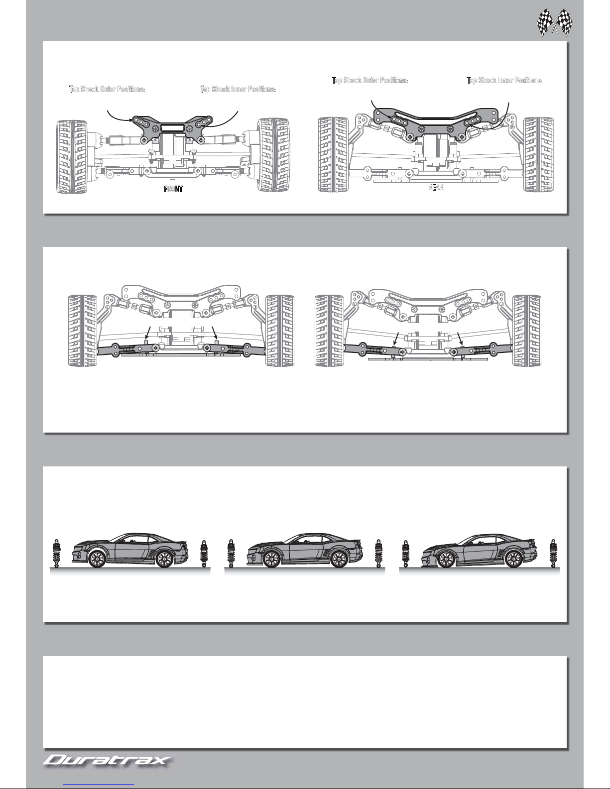
SHOCK ADJUSTMENTS
Top Shock Outer Positions:
s Decreases steering
s Quicker suspension reaction
FRONT
Top Shock Inner Positions:
s More aggressive steering
s Smoother over bumps
Top Shock Outer Positions:
s Increase steering
s Quicker suspension reaction
Top Shock Inner Positions:
s More traction in corners
s Smoother over bumps
REAR
Screws adjusted so arms drop less.
Screws adjusted so arms drop more (more droop).
DROOP
Distance the chassis can lift from ride height before the wheels come off the ground.
More Front Droop:
More Front Droop: Increases chassis up travel when on throttle and decreases high speed steering, making vehicle turn smoother. Good for low traction and bumpy surfaces.
Less Front Droop:
Less Front Droop: Decreases chassis up travel when off throttle and under braking, making steering more aggressive. Good for high speed smooth surfaces.
More Rear Droop:
More Rear Droop: Increases chassis up travel when off throttle and under braking. Increases steering in low speed corners and under braking.
Less Rear Droop:
Less Rear Droop: Decreases steering in low speed corners, making the vehicle turn smoother.
More spacers on the front shock. More spacers on the rear shock.Same number of spacers front and rear.
RIDE HEIGHT
Distance the chassis sits from the ground and how much weight is transferred when the vehicle changes speed and direction.
Lower Rear:
Lower Rear: More rear traction but reduces steering.
Lower Front:
Lower Front: Increases steering but can cause
rear end to break loose.
11
11
12
12
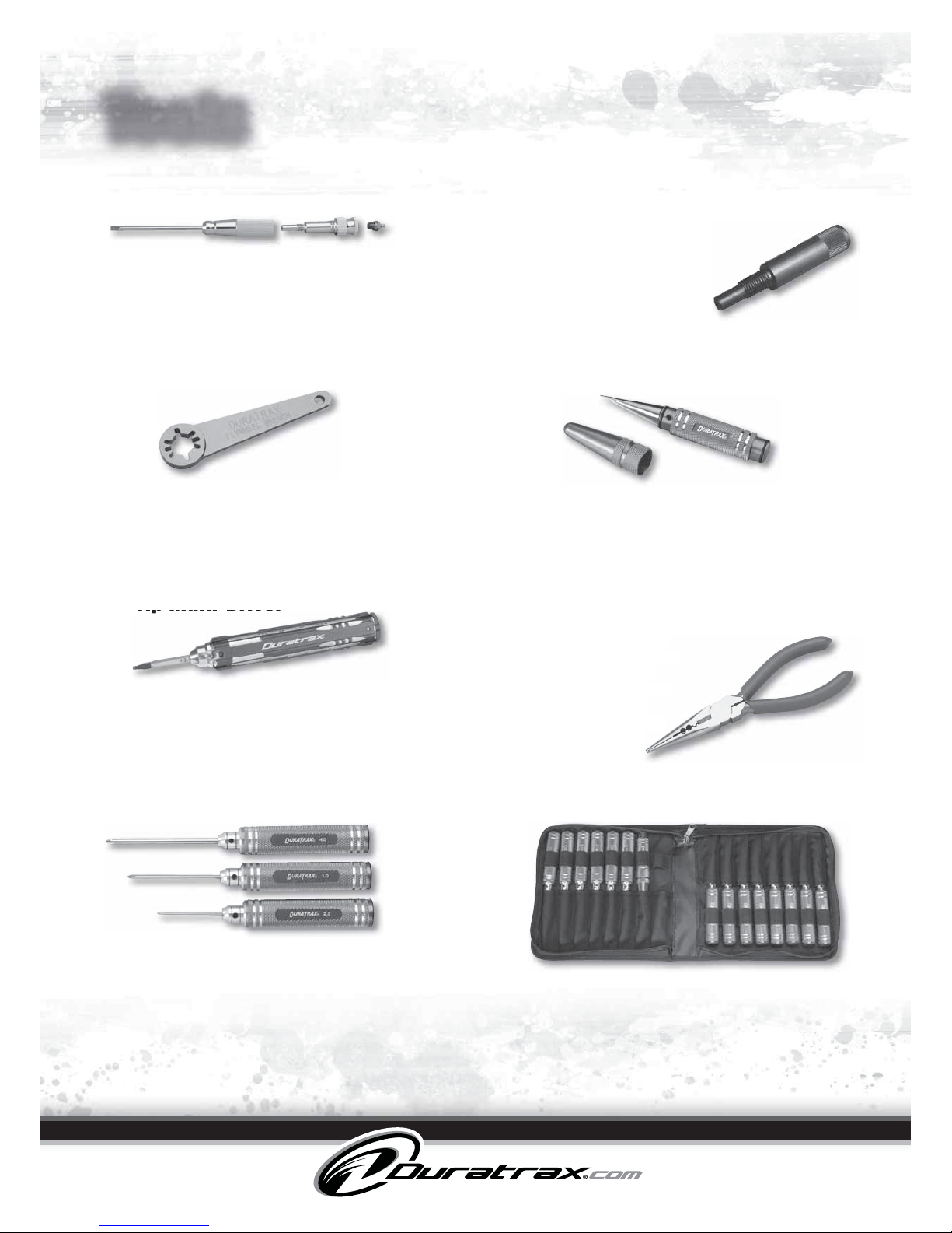
Tools
Engine Tuning Tool
Ultimate Flywheel Wrench
Ultimate Body Reamer
6” Long Nose Pliers
Tool Set and Pouch
Crankshaft Locking Tool
12-Tip Multi-Driver
Two tools for the price of one – a steel shank
screwdriver with a knurled, anodized aluminum
handle and a piston locking tool! Includes
storage space for one spare glow plug.
DTXR0187
Slotted to fit 2-, 3- or 4-pin flywheels, this
aluminum wrench safely holds the flywheel
while you tighten or loosen clutch nuts —
without stressing internal engine components.
DTXR1105
The extra-sharp point starts holes precisely
where you want them, while the knurled
aluminum handle provides a secure grip. A
snap-on cap protects the tip when not in use.
DTXR1157
Forged from chrome
alloy steel, these pliers
feature rubberized
handles and serrated
jaws for easy wire
bending, cutting and
stripping.
DTXR0300
Set includes 4 each of metric and SAE hex drivers,
3 each of slotted and Phillips screwdrivers, plus
an Ultimate Body Reamer — all organized in
a zippered, 15-pocket tool pouch (pouch also
available separately).
DTXR0400
15-Piece Ultimate Tool Set w/Pouch
DTXR0401
15-Pocket Ultimate Tool Pouch Only
Tools in these convenient sets have knurled, blue-anodized
aluminum handles; hardened steel shafts; precision-ground
tips; and tip sizes engraved onto the handles.
DTXR0179
3-Piece Ultimate Slotted Screwdriver Set (2, 3 and 4 mm)
DTXR0183
3-Piece Ultimate Phillips Screwdriver Set (2, 3 and 4 mm)
DTXR0292
4-Piece Ultimate Hex Driver Set (1.5, 2, 2.5 and 3 mm)
DTXR0297
4-Piece Ultimate Ball Driver Set (1.5, 2, 2.5 and 3 mm)
DTXR0392
4-Piece Ultimate Hex Driver Set (.050, 1/16, 5/64 and 3/32 in)
This handy tool threads into
your engine’s glow plug
socket, locking the piston
and crankshaft to prevent
them from turning while
you perform maintenance.
DTXR1100
The aluminum handles holds six shanks with 12 adjustablelength tips, suited for many different driving needs. Rotate
the end cap to select the tip you need. Tips included:
1.5 mm and 2 mm slotted; 0 and 00 Phillips; and 1.5 mm,
2.0 mm, 2.5 mm, 3.0 mm, .050”, 1/16”, 5/64”, and 3/32”.
DTXR1165
Tip Multi Driver
Ultimate Tool Sets
me
pliers
d
ed
nd
 Loading...