

Page 1
®
Page 2
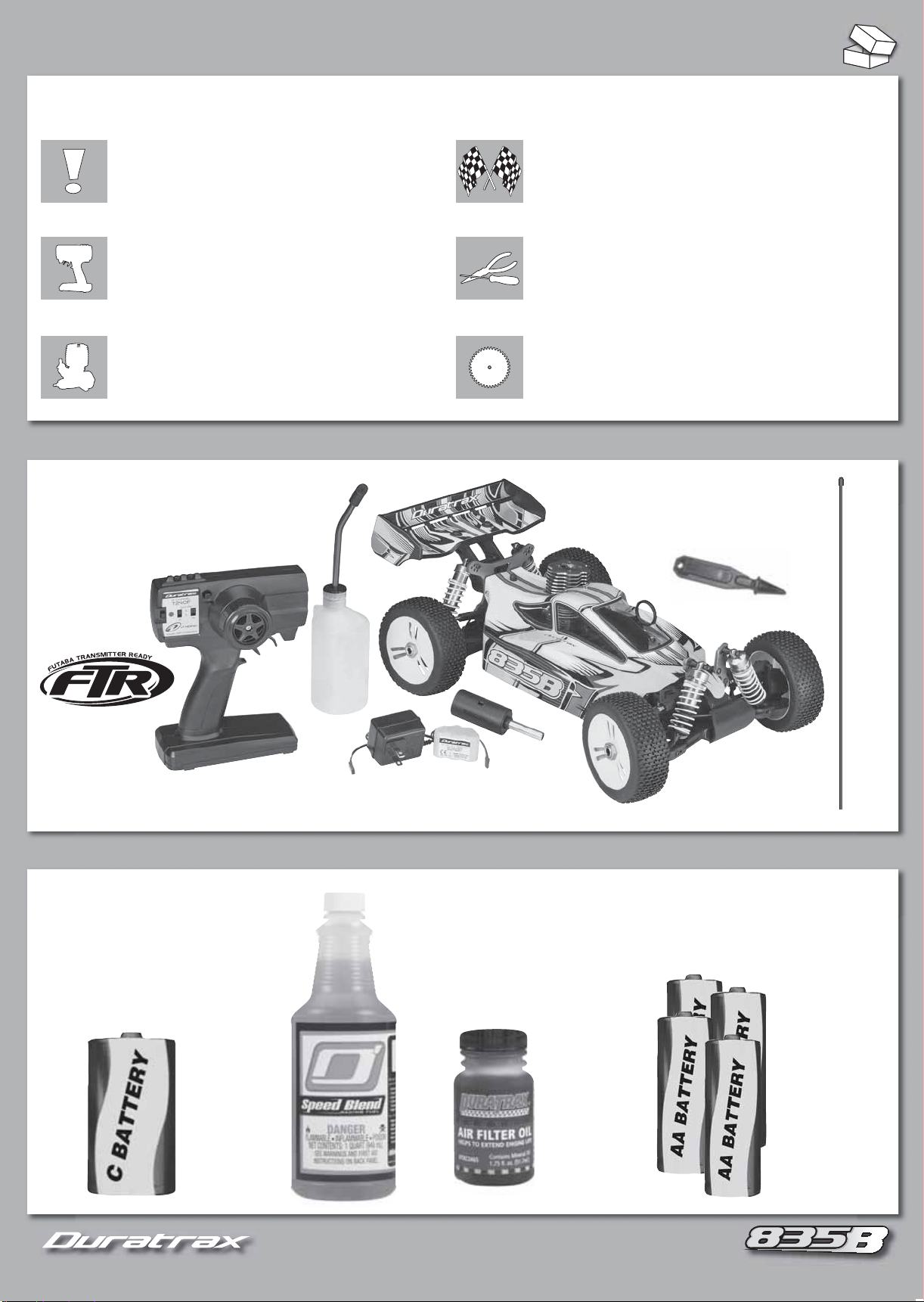
TABLE OF CONTENTS
2
SAFETY PRECAUTIONS AND WARRANTY ...............3 TUNING GUIDE ..................................................8-10
PREPARE TO RUN THE 835B ............................... 4-5
ENGINE RUNNING & MAINTENANCE ......................6 REPLACEMENT PARTS ........................................34+
CONTENTS
™
Duratrax T240F 2.4 GHz Transmitter
Fuel
Bottle
Rx Battery
Charger
Receiver
Battery
ASSEMBLY GUIDE ........................................... 11-33
Engine Stop Tool
Glow
Starter
Chassis
Antenna
Tube
REQUIRES
“C” Alkaline
Battery
(Glow Starter)
Fuel
(ODOP4520)
“AA” Alkaline
Air Filter Oil
(DTXC2465)
2
Batteries x4
(Transmitter)
Page 3
3
SAFETY PRECAUTIONS
To prevent injury and damage to property, follow these safety precautions
when operating any radio control vehicle.
Keep all spectators a safe distance away from the vehicle.
ALWAYS turn the transmitter on before the receiver.
NEVER touch any part of the engine or exhaust as they can become very hot.
ALWAYS keep model engine fuel out of the reach of children and follow
precautions on the container.
NEVER run your model indoors. Fuel powered vehicles create harmful fumes.
NEVER smoke and avoid ignition sources when using model engine fuel.
Model engine fuel is poisonous and fl ammable. Keep away from open fl ame.
Use a mat or towel when working on your model to protect your work surface.
Do NOT run your radio control vehicle in cold weather as plastic parts
may become brittle.
WA RNING: This product contains a chemical known to the State of California to
cause cancer.
SPECIFICATIONS & DESCRIPTION CHANGES
All
information found in this manual is subject to change without notice. Visit Duratrax.com for the latest updates and information on your
model. Duratrax maintains no responsibility for inadvertent errors in this manual.
LIMITED WARRANTY
Duratrax guarantees this kit to be free from defects in
materials or workmanship for 90 days (3 years for the
engine) after the date of purchase. Duratrax will repair
or replace at no charge any incorrectly made part.
Your receipt or invoice at time of purchase is your
proof of purchase and is required for Duratrax to
honor any warranty. Duratrax reserves the right to
change or modify this warranty without notice.
For warranty repairs, contact or send to:
Hobby Services
3002 N. Apollo Drive Suite 1
Champaign, IL 61822
ATTN: Service Department
Phone: (217) 398-0007
9:00 am – 5:00 pm Central Time M-F
E-mail: hobbyservices@hobbico.com
www.hobbyservices.com
IF the buyer is not prepared to accept the liability
associated with the use of this product, buyer
is advised to return kit immediately in new and
unused condition to the place of purchase.
STRESS-TECH PARTS GUARANTEE
Stress-Tech parts are guaranteed for 12 months from the date of purchase.
Check the parts list for items covered under the Stress-Tech guarantee.
Should a Stress-Tech part break during the fi rst 12 months after purchase,
return the part to Hobby Services and we will send you a FREE replacement.
To receive your FREE replacement Stress-Tech part, include the following and
return to Hobby Services at the address above:
1. Broken part
2. Part number and description of the broken part
3. COPY of your dated purchase invoice or receipt
4. Name, phone number and shipping address
REPAIR SERVICE
Hobby Services offers repair services after the 90 day limited warranty or 12
month Stress-Tech parts replacement for a minimal charge.
Follow these instructions for your repair request:
1.
Most circumstances require the return of the ENTIRE vehicle. STRESS-TECH
requires ONLY the broken part to be returned following the instructions above.
2. Turn off the transmitter and remove the batteries.
3. Empty fuel tank on nitro vehicles.
4. Include written instructions listing
THOROUGH
phone number. IF you expect the repair to be covered under the 90 day
limited warranty, include copy of receipt or invoice with date of purchase.
description of the problem, service needed and your
ALL
items being returned with a
DAYTIME
5. Send to Hobby Services at the address above. When shipping your item(s)
to us, we recommend that you insure them and use a company that offers
tracking service (such as UPS or Federal Express).
We will carefully inspect your item and notify you of our fi ndings. You will be
advised of your options for return, repair, or replacement. Please note that
items sent back unrepaired will carry a return shipping and service charge.
Hobby Services accepts Visa®, MasterCard®, or you can send a check. We can
return the item C.O.D., but additional charges will apply.
082E
Included radio system is not fully compliant with French regulations.
TM
NiMH
3
Page 4
4
1
2
4
3
6
5
4
1
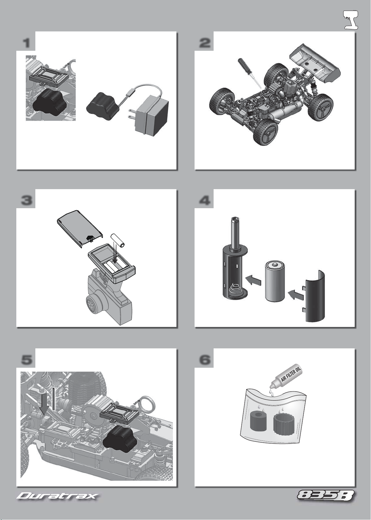
CHARGE THE RECEIVER
BATTERY
Remove the battery.
Allow 8 hours to fully
charge the battery.
2
CHECK SCREWS
Double-check all screws and nuts
to be sure they are tight.
3
5
INSTALL TRANSMITTER
BATTERIES
+
–
–
+
INSTALL ANTENNA TUBE
AND RECEIVER BATTERY
+
+
–
4
6
INSTALL GLOW STARTER
BATTERY
OIL AIR FILTER
Apply air filter oil (DTXC2465) onto the foam element, squeezing
s
the element until it is completely coated with the oil.
TIP! Placing the element in a plastic bag will help keep your hands clean.
s
Remove any excess oil with a paper towel.
s
4
4
Page 5
5
7
8
5
10
9
12
11
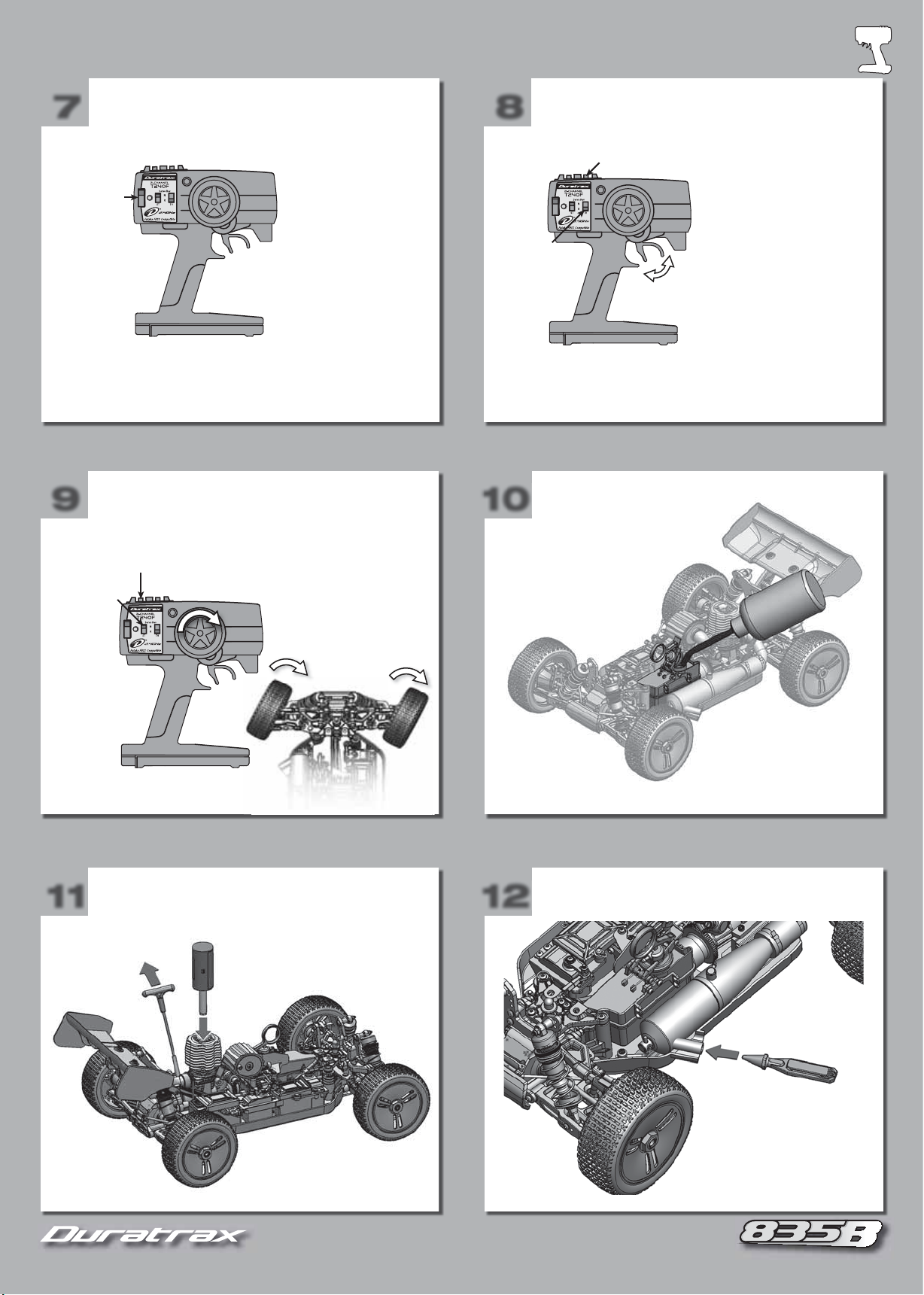
7
If you ever need to re-bind the receiver, turn on the system and press
and hold the bind button on the receiver until the L.E.D. turns solid green.
POWER UP TRANSMITTER CHECK THROTTLE
On/Off
2.4 GHz
Check radio operation
before each run!
8
Throttle
Reverse
Switch
Throttle Trim
Forward
2.4 GHz
Brake
Check radio operation
before each run!
9
Steering Servo
Reverse Switch
11
CHECK STEERING FUEL THE CAR
START THE ENGINE STOP THE ENGINE
Steering Trim
2.4 GHz
Check radio operation
before each run!
10
12
See page 6 for starting
and engine break-in.
To stop your 835b engine,
place the pointed end of
the engine tool into the
exhaust outlet (stinger).
This will block the exhaust
and stop the engine.
5
5
Page 6
6
BREAK-IN PROCEDURE
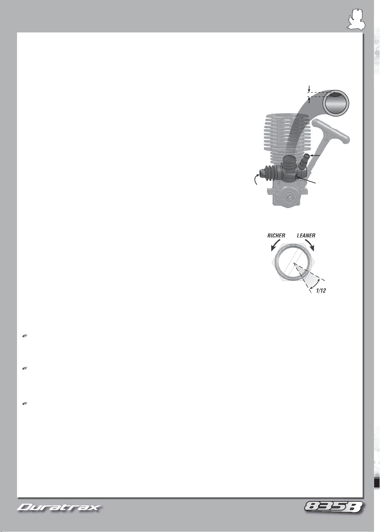
When starting, hold the throttle slightly open. If the engine is diffi cult to turn over, loosen glow plug 1/2-turn before starting engine (this allows
some compression to escape while allowing the engine to start). Once engine starts, tighten the glow plug.
IMPORTANT! FLOODED ENGINE:
If you are still having problems turning the engine over, it is fl ooded (too much fuel inside the engine).
1. Remove glow plug and turn vehicle upside down, pointing away from you.
2. Pull the recoil 5 times (clearing engine of fuel).
3. Replace glow plug.
4. Repeat starting engine steps.
Engine break in will be accomplished with the fi rst 5 tanks of fuel. (NOTE: Full break-in
may take up to 15 tanks.)
1. During break-in, run with the body off to keep the engine cool.
2. Keep air fi lter on at all times.
3. Run on smooth, hard surface.
4. Make sure you have extra glow plugs. Break-in puts stress on the glow plug and it may
need to be replaced.
TANK 1
Run very rich allowing fuel to carry as much oil as possible to lubricate internal engine parts.
1. High Speed Needle Valve: Check this setting before running. Close the high speed
needle by rotating it clockwise until you just feel resistance, then open to 4 full turns out
(counterclockwise).
2. Run at medium speeds, slowly accelerating and decelerating.
3. If engine does not stay running consistently, increase idle speed by turning the idle stop screw clockwise.
4. DO NOT allow the tank to run out of fuel during break-in.
5. Stop engine and allow it to cool approximately 10 – 15 minutes.
TANKS 2-4
1. For each additional tank, lean high speed needle 1/12 turn from the previous tank’s setting.
2.
Stop engine, allowing it to cool approximately 10 – 15 minutes, between each tank.
TANK 5
1. Lean high speed needle an additional 1/12 turn from Tank 4 setting.
2. The engine should now be very close to fi nal tune and be broken in and ready to be performance tuned.
TUNING TIPS (Adjust only after the engine is fully broken in.)
IMPORTANT!
test the results.
High Speed Needle:
small amount of smoke. The goal is to tune the engine to make good power without overheating. Engine temperature should stay around 250°
F (132° C) using a temperature gauge (Duratrax Flashpoint
Note:
This temperature is a “guideline” only. Your engine may run
slightly warmer or cooler depending on conditions: fuel, track, and how you drive.
Low Speed Needle:
Controls fuel mixture at low throttle settings (idle). To check this setting, keep the throttle at idle and pinch the fuel line
close to the carburetor. A correct setting will increase the engine speed after 2-3 seconds and then lose speed.
• If it slows too quickly, the mixture is too lean. Open the low speed needle (counterclockwise).
• If it takes longer than 4 seconds to slow down, the mixture is too rich. Close the low speed needle (clockwise).
Idle Stop Screw:
Adjust this screw to set the idle speed so the wheels do not rotate when you lift the vehicle off of the ground. When looking
into the carburetor, the barrel should be about 1mm from fully closed.
CARE AND MAINTENANCE
1. Keep engine clean and free of dirt.
2. Do not over lean engine.
3. Run all of the fuel out of the engine before storing.
4.
Use after run oil and work it into the engine by turning the fl ywheel before storing
.
5. Do not use a fuel with a nitromethane content over 30%.
667
When starting, hold the throttle slightly open. If the engine is diffi cult to turn over, loosen glow plug 1/2-turn before starting engine (this allows
some compression to escape while allowing the engine to start). Once engine starts, tighten the glow plug.
IMPORTANT! FLOODED ENGINE:
1. Remove glow plug and turn vehicle upside down, pointing away from you.
2. Pull the recoil 5 times (clearing engine of fuel).
3. Replace glow plug.
4. Repeat starting engine steps.
Engine break in will be accomplished with the fi rst 5 tanks of fuel. (NOTE: Full break-in
may take up to 15 tanks.)
1. During break-in, run with the body off to keep the engine cool.
2. Keep air fi lter on at all times.
3. Run on smooth, hard surface.
4. Make sure you have extra glow plugs. Break-in puts stress on the glow plug and it may
need to be replaced.
TANK 1
Run very rich allowing fuel to carry as much oil as possible to lubricate internal engine parts.
1. High Speed Needle Valve: Check this setting before running. Close the high speed
needle by rotating it clockwise until you just feel resistance, then open to 4 full turns out
(counterclockwise).
2. Run at medium speeds, slowly accelerating and decelerating.
3. If engine does not stay running consistently, increase idle speed by turning the idle stop screw clockwise.
4. DO NOT allow the tank to run out of fuel during break-in.
5. Stop engine and allow it to cool approximately 10 – 15 minutes.
If you are still having problems turning the engine over, it is fl ooded (too much fuel inside the engine).
~1mm
HIGH SPEED
NEEDLE
LOW SPEED
NEEDLE
IDLE STOP
SCREW
TANKS 2-4
1. For each additional tank, lean high speed needle 1/12 turn from the previous tank’s setting.
2.
Stop engine, allowing it to cool approximately 10 – 15 minutes, between each tank.
TANK 5
1. Lean high speed needle an additional 1/12 turn from Tank 4 setting.
2. The engine should now be very close to fi nal tune and be broken in and ready to be performance tuned.
TUNING TIPS (Adjust only after the engine is fully broken in.)
IMPORTANT! Always run the engine for 1-2 minutes to warm up temperature before tuning! Only use “small” adjustments (1/12 turn at a time) and
test the results.
High Speed Needle: Controls the fuel/air mixture at high throttle settings. A properly tuned engine will accelerate smoothly and exhaust a
small amount of smoke. The goal is to tune the engine to make good power without overheating. Engine temperature should stay around 250°
F (132° C) using a temperature gauge (Duratrax Flashpoint™, DTXP3100).
slightly warmer or cooler depending on conditions: fuel, track, and how you drive.
Low Speed Needle:
close to the carburetor. A correct setting will increase the engine speed after 2-3 seconds and then lose speed.
• If it slows too quickly, the mixture is too lean. Open the low speed needle (counterclockwise).
• If it takes longer than 4 seconds to slow down, the mixture is too rich. Close the low speed needle (clockwise).
Idle Stop Screw:
into the carburetor, the barrel should be about 1mm from fully closed.
CARE AND MAINTENANCE
1. Keep engine clean and free of dirt.
2. Do not over lean engine.
3. Run all of the fuel out of the engine before storing.
4.
Use after run oil and work it into the engine by turning the fl ywheel before storing
5. Do not use a fuel with a nitromethane content over 30%.
Always run the engine for 1-2 minutes to warm up temperature before tuning! Only use “small” adjustments (1/12 turn at a time) and
Controls the fuel/air mixture at high throttle settings. A properly tuned engine will accelerate smoothly and exhaust a
, DTXP3100).
Controls fuel mixture at low throttle settings (idle). To check this setting, keep the throttle at idle and pinch the fuel line
Adjust this screw to set the idle speed so the wheels do not rotate when you lift the vehicle off of the ground. When looking
Note:
This temperature is a “guideline” only. Your engine may run
6
Page 7
Engine Tools & Accessories
.
Engine Tuning Screwdriver
Standard slot-head screwdriver has a 120 mm
hardened steel shaft with 3.2 mm wide magnetized
tip and rubberized, hexagonal handle.
DTXR0185
™
TrakPower
Speed Wash
Nitro Cleaner
Applies with or without water and is safe
for titanium, aluminum, fiberglass, clear
coat, stainless steel, chrome, rubber,
plastic, vinyl and leather. 32 fl oz (946 mL).
TKPC8001
Air Filter Oil
Treats foam air filter elements
to increase filtering capacity
and extend engine life. Handy
1.75 fl oz (51.7 mL) bottle fits
easily into a tool box or tote.
DTXC2465
Rapid Heat
Twist-on for a secure connection
to heat your glow plug. Twist
the other way for easy removal.
Includes NiCd and AC charger.
DTXP3000
™
Glo-Starter
Deluxe Car Wrenches
Deluxe includes 6
socket head sizes
and stores up to 4
glow plugs. Ultimate
adds a slotted/Phillips
screwdriver bit and
19 mm socket for 1/8 car
wheel nuts.
DTXR1170
DTXR1175
Kwik-Pit
A squeeze on the clear plastic body
lets you control fuel flow. The 5 in
(63.5 mm) long aluminum spout
features a curved tip for no-spill refills
and a tip cap to prevent leaks. For
glow fuel only.
DTXP0125
DTXP0150
Deluxe Car Wrench
Ultimate Car Wrench
™
Fuel Bottles
250 cc (8.5 fl oz) Fuel Bottle
500 cc (17.0 fl oz) Fuel Bottle
O’Donnell Racing Fuel
Speed Blend improves fuel
economy and pushes engine
performance to the absolute
peak. Race Blend simplifies
tuning and reduces engine heat
and internal wear.
ODOP3320
ODOP3325
ODOP3330
ODOP4520
ODOP4525
ODOP4530
20% Racing Fuel Quart
25% Racing Fuel Quart
30% Racing Fuel Quart
20% Speed Blend Quart
25% Speed Blend Quart
30% Speed Blend Quart
r
rench
®
FlashPoint™ Infrared
Temperature Gauge
Glow Plugs
Hand-assembled with heat resistant coils.
Carbon Speed is medium-hot for informal
racing and sport use. Gold Racing Plug is for
higher nitro fuels and competitive driving.
DTXG3003
DTXG3005
Carbon Speed Plug
Gold Racing Plug
Just point and press for
fast, accurate, no-touch
temperature readings of
engines, motors, batteries
and more. Works in seconds
and turns off automatically
after 15 seconds of inactivity.
DTXP3100
7
Page 8
8
TUNING GUIDE
As a starting point, make sure your car has equal lengths on shocks, camber links and steering rods on both
sides (left and right). Front and rear do not need to be equal.
Rear Hole:
Forward Hole:
Negative Camber
Positive Camber
Toe-Out:
Toe-In:
Toe-In
8
Lower Rear:
More rear traction but reduces steering.
Lower Front:
Increases steering but can cause rear
end to lose traction.
As a starting point, make sure your car has equal lengths on shocks, camber links and steering rods on both
sides (left and right). Front and rear do not need to be equal.
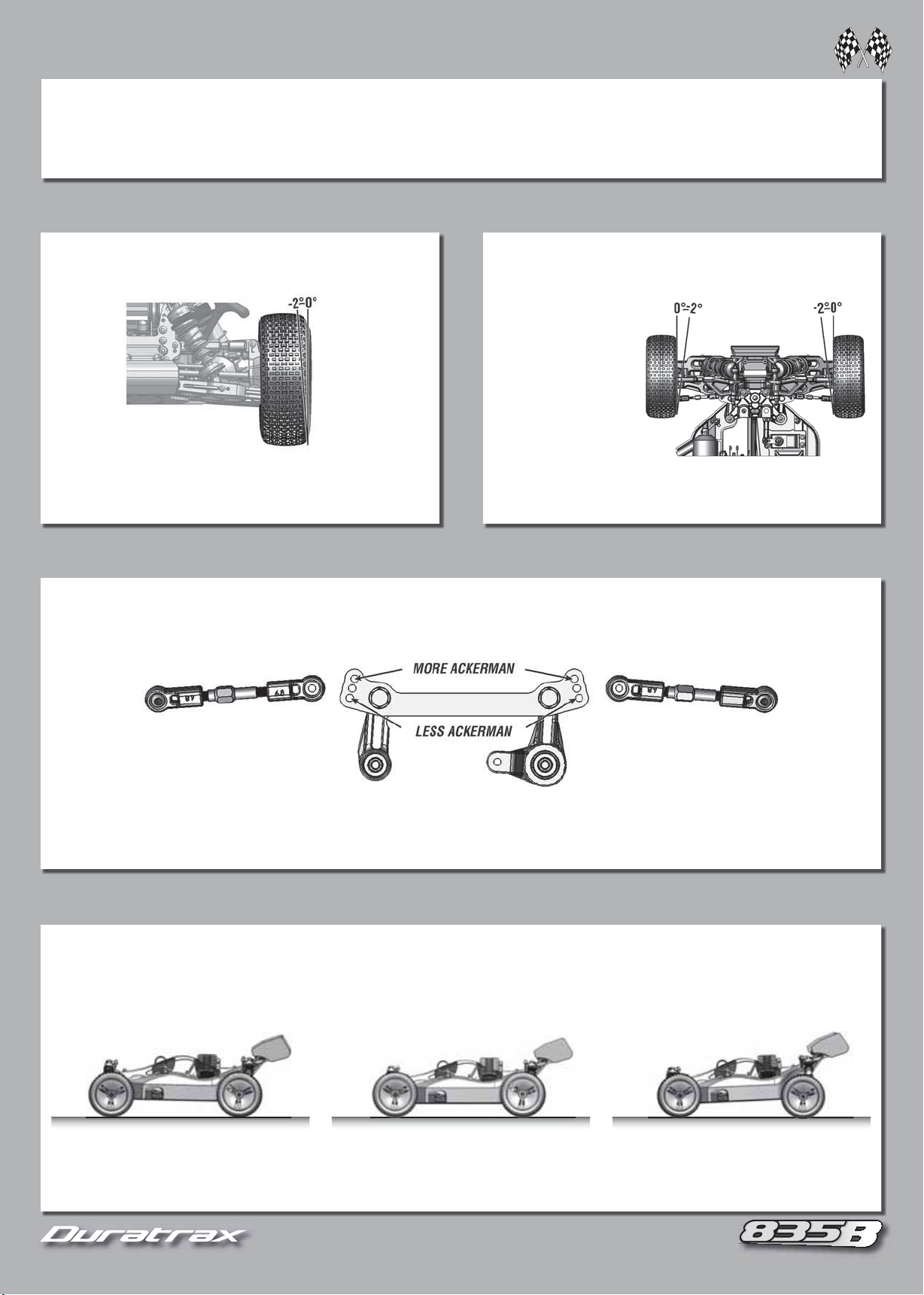
CAMBER
Angle of the tire and wheel in relation to the ground when
viewed from the front.
Negative Camber =
• Improved traction while corning.
• Adds overall stability.
Positive Camber = Tire and wheel lean outward (NOT recommended).
Top of the tire and wheel lean inward (Typically 0° to -2°)
FRONT TOE-IN AND TOE-OUT
Direction the wheels point in relationship with each other,
when viewed from the front.
Toe-In: Front of the
wheels point toward each
other. (Typically 0 to -2°)
• Increased stability when
accelerating. Decreased
steering when entering
a corner.
Toe-Out: Fronts of the wheels point away from each other.
• Decreased stability when accelerating and increased steering
when entering a corner.
ACKERMAN
The difference in turning angle between the inside wheel and outside wheel in a turn.
Toe-In
Forward Hole: More initial steering into corner. Steering is
more aggressive. Better for tight technical tracks.
Rear Hole: Less initial steering into a corner. Smoother steering
response. Better for large fl owing tracks.
RIDE HEIGHT
Distance the chassis sits from the ground and how much weight is transferred when the vehicle changes speed and direction.
Rotate the collar on the shock to change ride height. Adjust left and right equally.
Lower Rear:
More rear traction but reduces steering.
Lower Front:
end to lose traction.
8
8
Increases steering but can cause rear
Page 9
9
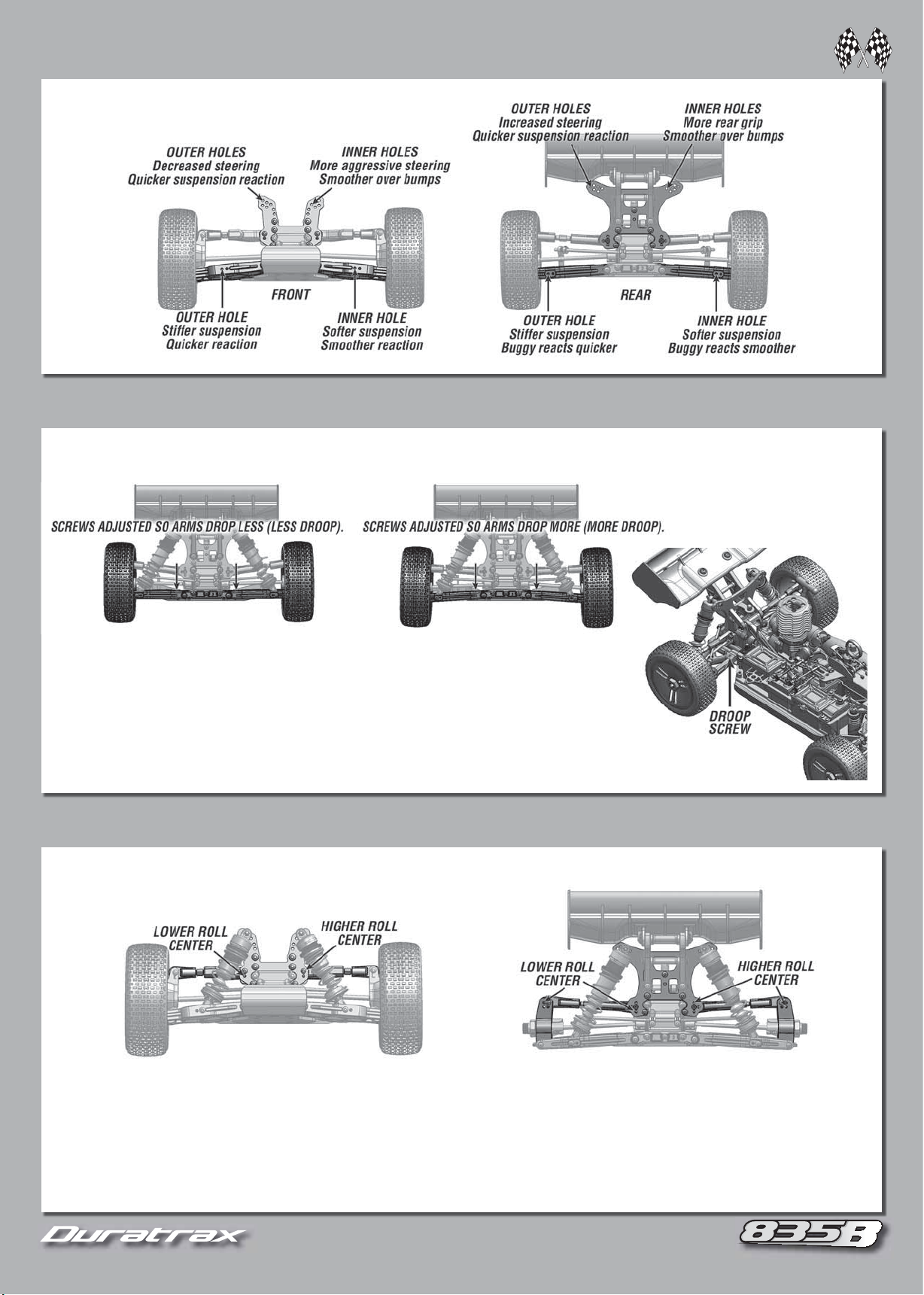
SHOCK ADJUSTMENTS
More Front Droop:
Increases chassis up travel when on throttle and decreases high speed steering,
making vehicle turn smoother. Good for low traction and bumpy surfaces.
Less Front Droop:
Decreases chassis up travel when on throttle, making steering more aggressive.
Good for high speed smooth surfaces.
More Rear Droop:
Increases chassis up travel when off throttle and under braking. Increases
steering in low speed corners and under braking.
Less Rear Droop:
Decreases steering in low speed corners, making the vehicle turn smoother.
9
Higher Roll Center:
Increases the chassis roll on the rear
of the car. Increases rear traction on-power. Decreases rear
traction during braking.
Lower
Roll Center:
Decreases the chassis roll at the rear of
the car. Decreases rear on-power traction. Reduces corner
entry steering. Increases corner exit steering.
Higher Roll Center:
Reduces chassis roll and on-power
steering. The car feels more responsive. Reduces front traction
going into corners. Good for high grip, technical tracks.
Lower
Roll Cente
Increases the chassis roll and on-power
steering. Steering is less responsive, but smoother and more
stable. Better for smooth tracks with high speed corners.
FRONT ROLL CENTER
REAR ROLL CENTER
DROOP
Distance the chassis can lift from ride height before the wheels come off the ground.
More Front Droop:
Less Front Droop:
More Rear Droop:
Less Rear Droop:
Increases chassis up travel when on throttle and decreases high speed steering,
making vehicle turn smoother. Good for low traction and bumpy surfaces.
Decreases chassis up travel when on throttle, making steering more aggressive.
Good for high speed smooth surfaces.
Increases chassis up travel when off throttle and under braking. Increases
steering in low speed corners and under braking.
Decreases steering in low speed corners, making the vehicle turn smoother.
ROLL CENTER
Point at which the vehicle rolls laterally when cornering.
FRONT ROLL CENTER
Higher Roll Center:
steering. The car feels more responsive. Reduces front traction
going into corners. Good for high grip, technical tracks.
Lower
Roll Center:r:
steering. Steering is less responsive, but smoother and more
stable. Better for smooth tracks with high speed corners.
Reduces chassis roll and on-power
Increases the chassis roll and on-power
REAR ROLL CENTER
Higher Roll Center:
of the car. Increases rear traction on-power. Decreases rear
traction during braking.
Lower
Roll Center:
the car. Decreases rear on-power traction. Reduces corner
entry steering. Increases corner exit steering.
Increases the chassis roll on the rear
Decreases the chassis roll at the rear of
9
9
Page 10
101010
Check before every run:
1. All hardware to be sure everything is tight.
2. Transmitter batteries.
3. Moving parts are free from binding.
4. Parts are not broken or damaged.
5. Wires are properly connected.
6. Remove dirt or debris from chassis and moving parts.
7. Bearings should roll smoothly.
8. Shocks should operate smoothly. Check for leakage and refi ll as needed.
9. Gear mesh between the spur and clutch gears.
WHEELBASE
Decreases off power steering. Better
through rough sections. More stable.
More on power steering.
Increases rear on power traction.
More off power steering.
Thinner:
Increased traction. Chassis transitions quicker. Increased chance of the chassis
bottoming out. Better for rough tracks
Thicker:
Decreased traction. Chassis transitions slower. Decreased chance of chassis
bottoming out. Better for smooth tracks.
FRONT:
Thinner:
Increased off power steering (too thin will make it inconsistent.) Decreased on power steering.
Thicker:
Increased stability while braking into a corner. Increased on power steering exiting a corner.
CENTER:
Thinner:
Better for rough track conditions. Causes the front to unload under acceleration. Decreases on power steering.
Thicker:
Better acceleration. Increases on power steering. Less stable. Better for smooth high bite tracks.
REAR:
Thinner:
More rear traction in the corners. Increases mid corner steering.
Thicker:
Decreases rear traction in the corners. Increases forward traction. Less mid corner steering
SHORTER WHEELBASE
MEDIUM WHEELBASE
LONGER WHEELBASE
Distance between the front and rear wheels.
SHORTER WHEELBASE
Increases rear on power traction.
More off power steering.
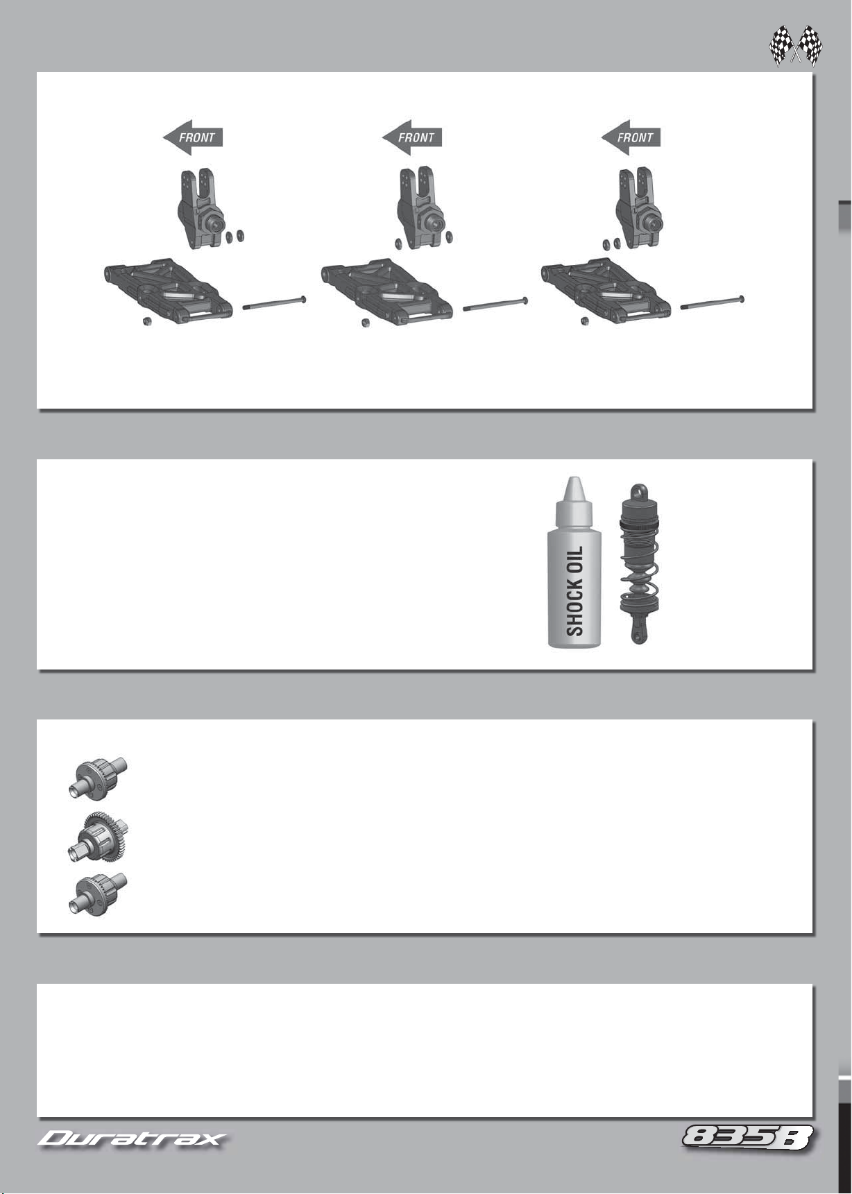
SHOCK OIL
MEDIUM WHEELBASE
LONGER WHEELBASE
Decreases off power steering. Better
through rough sections. More stable.
More on power steering.
Thinner:
bottoming out. Better for rough tracks
Thicker:
bottoming out. Better for smooth tracks.
Increased traction. Chassis transitions quicker. Increased chance of the chassis
Decreased traction. Chassis transitions slower. Decreased chance of chassis
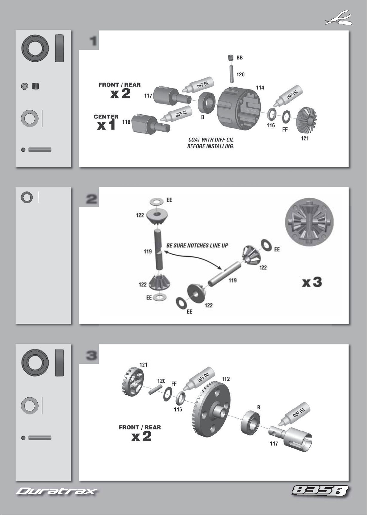
DIFFERENTIAL OIL
FRONT:
CENTER:
REAR:
Thinner:
Thicker:
Thinner:
Thicker:
Thinner:
Thicker:
Increased off power steering (too thin will make it inconsistent.) Decreased on power steering.
Increased stability while braking into a corner. Increased on power steering exiting a corner.
Better for rough track conditions. Causes the front to unload under acceleration. Decreases on power steering.
Better acceleration. Increases on power steering. Less stable. Better for smooth high bite tracks.
More rear traction in the corners. Increases mid corner steering.
Decreases rear traction in the corners. Increases forward traction. Less mid corner steering
CHASSIS MAINTENANCE TIPS
Check before every run:
1. All hardware to be sure everything is tight.
2. Transmitter batteries.
3. Moving parts are free from binding.
4. Parts are not broken or damaged.
5. Wires are properly connected.
6. Remove dirt or debris from chassis and moving parts.
7. Bearings should roll smoothly.
8. Shocks should operate smoothly. Check for leakage and refi ll as needed.
9. Gear mesh between the spur and clutch gears.
10
Page 11

11
FOR MAINTENANCE AND REPAIRS ON YOUR 835B
FOR MAINTENANCE AND REPAIRS ON YOUR 835B
11
Page 12
12
B (x3)
1
2
3
8x16mm
BB (x3)
4x5mm
FF (x3)
6x10mm
120 (x3)
2.5x13mm
EE (x12)
4x7mm
1
2
B (x2)
8x16mm
FF (x2)
6x10mm
120 (x2)
2.5x13mm
3
12
Page 13
131313
4
5
6
B (x1)
8x16mm
FF (x1)
6x10mm
120 (x1)
2.5x13mm
R (x12)
3x12mm
4
5
B (x2)
8x16mm
BB (x1)
4x5mm
6
13
Page 14
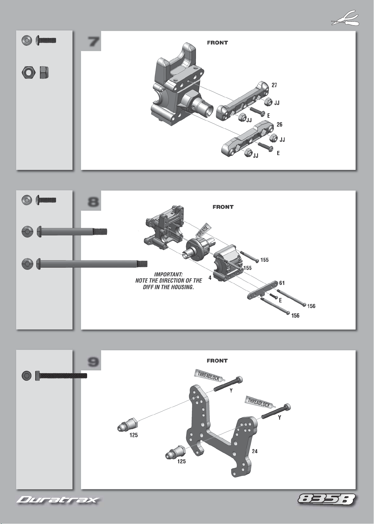
14
7
8
9
E (x2)
3x10mm
JJ (x4)
4mm
E (x1)
3x10mm
7
8
155 (x2)
4x37mm
156 (x2)
4x62mm
Y (x2)
3x30mm
9
14
Page 15
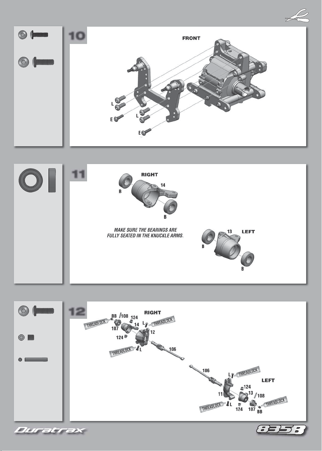
151515
10
11
12
E (x2)
3x10mm
L (x4)
4x12mm
10
11
B (x4)
8x16mm
L (x4)
4x12mm
BB (x2)
4x5mm
12
108 (x2)
2.5x16mm
15
Page 16
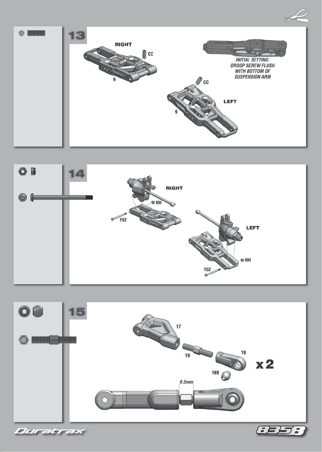
161616
14
15
CC (x2)
13
4x12mm
HH (x2)
3mm
13
14
152 (x2)
3x40mm
169 (x2)
19 (x2)
5x30mm
15
16
Page 17

17
16
17
18
K (x2)
3x22mm
HH (x2)
3mm
HH (x2)
3mm
16
17
JJ (x2)
4mm
152 (x2)
3x40mm
157 (x2)
4x70mm
AA (x2)
3x10mm
158 (x2)
18
FRONT
17
x2
Page 18

18
20
21
Z (x2)
19
3x3mm
149 (x2)
D (x2)
3x8mm
19
20
J (x2)
3x18mm
21
18
Page 19

19
23
24
B (x2)
22
8x16mm
BB (x1)
4x5mm
E (x2)
3x10mm
22
23
JJ (x4)
4mm
E (x1)
3x10mm
155 (x2)
4x37mm
24
156 (x2)
4x62mm
19
Page 20

20
26
27
25
Y (x2)
3x30mm
X (x2)
3x20mm
25
26
E (x1)
3x10mm
27
20
Page 21

21
29
30
E (x2)
28
3x10mm
L (x2)
4x12mm
28
29
B (x4)
8x16mm
BB (x2)
4x5mm
108 (x2)
2.5x16mm
HH (x2)
3mm
153 (x2)
3x45mm
30
21
Page 22

22
32
33
CC (x2)
31
4x12mm
HH (x2)
3mm
31
32
K (x2)
3x22mm
22 (x2)
5x50mm
168 (x2)
DD (x2)
3x8mm
HH (x2)
3mm
33
JJ (x2)
4mm
156 (x2)
4x62mm
22
Page 23

232323
35
36
F (x6)
34
3x12mm
34
35
M (x2)
4x20mm
AA (x2)
3x10mm
158 (x2)
36
23
REAR
x2
Page 24

24
38
39
Z (x2)
37
3x3mm
149 (x2)
D (x2)
3x8mm
37
38
J (x2)
3x18mm
39
24
Page 25

25
41
42
HH (x1)
40
3mm
154 (x1)
3x50mm
C (x4)
6x10mm
40
41
DD (x2)
3x8mm
HH (x2)
3mm
42
25
Page 26

26
44
45
T (x2)
43
4x12mm
U (x2)
4x14mm
43
44
159 (x4)
62 (x2)
4x45mm
45
26
Page 27

27
47
48
H (x4)
46
3x16mm
HH (x4)
3mm
Q (x6)
3x10mm
46
47
U (x2)
4x14mm
48
27
Page 28

28
50
51
E (x1)
49
3x10mm
F (x2)
3x12mm
L (x4)
4x12mm
49
50
R (x2)
3x12mm
HH (x2)
3mm
R (x2)
3x12mm
U (x4)
4x14mm
51
HH (x2)
3mm
28
Page 29

29
53
54
G (x4)
52
3x15mm
Z (x1)
3x3mm
52
53
F (x4)
3x12mm
54
29
Page 30

30
Z (x1)
56
57
55
3x3mm
U (x4)
4x14mm
55
56
DD (x2)
3x8mm
HH (x2)
3mm
57
30
Page 31

31
59
60
58
58
59
158 (x4)
3mm
60
31
Page 32

32
K (x2)
62
63
61
3x22mm
DD (x2)
3x8mm
HH (x2)
3mm
K (x2)
3x22mm
61
62
DD (x2)
3x8mm
HH (x2)
3mm
63
32
Page 33

33
65
66
A (x2)
64
5x10mm
64
65
V (x1)
3x10mm
DD (x1)
3x8mm
QQ (x4)
5x8x0.3mm
W (x4)
3x12mm
GG (x4)
3mm
66
33
Page 34

34
68
69
67
67
68
L (x1)
4x12mm
69
34
Page 35

35
71
72
F (x2)
70
3x12mm
70
71
Q (x2)
3x10mm
T (x1)
4x12mm
JJ (x4)
4mm
72
35
Page 36

36
74
75
73
T (x1)
4x12mm
BB (x1)
4x5mm
BB (x1)
4x5mm
73
74
MM (x4)
4x10mm
F (x8)
3x12mm
75
36
Page 37

37
77
78
E (x3)
76
3x10mm
76
77
DD (x1)
3x8mm
LL (x2)
E (x1)
3x10mm
H (x1)
3x16mm
78
P (x1)
2.6x6mm
Z (x4)
3x3mm
HH (x1)
3mm
37
Page 38

38
80
81
79
Q (x6)
3x10mm
F (x2)
3x12mm
79
80
N (x1)
3x8mm
HH (x4)
3mm
H (x2)
3x16mm
HH (x2)
3mm
81
38
Page 39

3939393939
PARTS LISTS, PARTS SETS, AND EXPLODED VIEWS
PARTS LISTS, PARTS SETS, AND EXPLODED VIEWS
39
Page 40

40
Z
t
3x3mm Set Screws
DTXC8660
G-27CX Engine
w/SG Crankshaft
DTXG0256
E7
Front Ball Bearing
DTXG0351
E8
Rear Ball Bearing
DTXG0364
E26
Carburetor Dust Boot
DTXG0404
E29
Carburetor Complete
DTXG0444
E40
E16
E17
E18
E22
Carburetor Body
DTXG0408
E36
E37
E38
Carburetor Retainer Set
DTXG0461
E18
E23
Carburetor Slide Valve
DTXG0413
E29
Carburetor O-Ring
DTXG0469
E1
E41
E34
E29
E26
E32
E30
Carburetor Gasket Set
E24
DTXG0432
E6
Connecting Rod
DTXG0474
E9
Backplate Set
DTXG0491
E2
E3
Piston/Cylinder Set
DTXG0546
E12
E16
Engine Gasket Set
DTXG0596
Backplate Screw Set
DTXG0509
E32
E31
E30
Fuel Inlet Nozzle Set
DTXG0556
E24
Low Speed Needle Set
E25
DTXG0598
Crankcase
DTXG0527
E5
E12
Head Button & Shim Se
DTXG0574
E39
Cylinder Head Screws
DTXG0610
SG Crankshaft
DTXG0539
E39
E4
Cylinder Head w/Screws
DTXG0579
E33
High Speed
Needle Socket
DTXG0618
40
Page 41

41
E35
E10
E20
E34
High Speed Needle Set
DTXG0621
E15
Start Shaft
DTXG0771
Silver Sport Glow Plug
DTXG3001
E19
One-Way Bearing
DTXG0637
E13
E14
Start Shaft Pin
DTXG0777
E11
Piston Pin Set
DTXG0646
Z
E27
Throttle Arm
DTXG0801
E21
Recoil Starter Set
DTXG0756
E41
E28
Throttle Stop Screw
DTXG0814
41
Page 42

42
ENGINE PARTS
This parts list shows the key number, part description, and
stock number for the replacement parts sets. When more
than one stock number is listed, that part is available in
multiple replacement parts sets. For contents found in each
replacment parts set, refer to the illustrated parts guide.
E1 Crankcase ..........................................................DTXG0527
E2 Cylinder Sleeve ................................................. DTXG0546
E3 Piston ................................................................ DTXG0546
E4 Cylinder Head (Blue) ......................................... DTXG0579
E5 Head Button ...................................................... DTXG0574
E6 Connecting Rod ................................................ DTXG0474
E7 Front Bearing .....................................................DTXG0351
E8 Rear Bearing ..................................................... DTXG0364
E9 SG Crankshaft ................................................... DTXG0539
E10 Piston Pin .......................................................... DTXG0646
E11 Piston Pin Retainer ........................................... DTXG0646
E12 Head Shim .................................... DTXG0596, DTXG0574
E13 Start Shaft Pin Spring ........................................DTXG0777
E14 Start Shaft Pin ....................................................DTXG0777
E15 Start Shaft ..........................................................DTXG0771
E16 Backplate Gasket ...........................DTXG0596, DTXG0491
E17 Backplate (for Recoil) .........................................DTXG0491
E18 3 x 6mm Backplate Screw ..............DTXG0509, DTXG0491
E19 One-Way Bearing ..............................................DTXG0637
E20 Recoil Starter ................................................... DTXG0756
E21 3 x 5mm Recoil Starter Screw .......................... DTXG0756
E22 Carburetor Body ............................ DTXG0408, DTXG0444
E23 Slide Valve ..................................... DTXG0413, DTXG0444
E24 Low Speed Needle O-Ring ...........DTXG0598, DTXG0432,
DTXG0444
E25 Low Speed Needle Valve .............. DTXG0598, DTXG0444
E26 Carb Dust Boot.......... DTXG0404, DTXG0432, DTXG0444
E27 Throttle Arm .................................. DTXG0801, DTXG0444
E28 Throttle Stop Screw ....................... DTXG0814, DTXG0444
E29 Carburetor O-Ring ......DTXG0469. DTXG0432, DTXG0444
E30 4 x 7.5 x .5mm Gasket .................. DTXG0432, DTXG0556,
DTXG0444
E31 Fuel Inlet Nozzle ........................... DTXG0556, DTXG0444
E32 5 x 7.5 x .5mm Gasket .................. DTXG0432, DTXG0556,
DTXG0444
E33 High Speed Needle Socket ........... DTXG0618, DTXG0444
E34 High Speed Needle O-Ring........... DTXG0621, DTXG0432,
DTXG0444
E35 High Speed Needle Valve ............. DTXG0621, DTXG0444
E36 Carburetor Retainer Pin .....................................DTXG0461
E37 3.5mm Lock Washer ..........................................DTXG0461
E38 3.5 x 5mm Carb Retainer Screw ........................DTXG0461
E39 3 x 15mm Cylinder Head Screw .... DTXG0610, DTXG0579
E40 Small Backplate O-Ring .....................................DTXG0491
E41 Throttle Stop Screw O-Ring .......... DTXG0814, DTXG0432
E35
E34
E33
E32
E28
E30
E31
E41
E22
E29
E23
E24
E26
E38
E25
E7
E37
E27
E36
E39
E4
E5
Z
E11
E1
E12
E12
E12
E2
E3
E11
E10
E6
E15
E16
E8
E17
E9
E40
E18
E13
E14
E20
E21
E19
E21
E21
42
Page 43

Tools & Accessories
43434343444444
Body Scissors & Reamer
Stainless steel blades of body scissors cut through plastics without
tearing. The reamer has a sharp tip with fluted blades to remove
debris as you cut.
DTXR1150
DTXR1151
DTXR1158
DTXR1160
DTXR1161
Pit Tech
Made of durable black
plastic, this gauge easily
and accurately measures
camber settings in 1°
increments from 10°
positive to 10° negative.
DTXR1146
Curved Tip Body Scissors
Straight Tip Body Scissors
Body Reamer
Straight Tip Body Scissors & Reamer (2-Piece Set)
Straight/Curved Tip Body Scissors & Reamer (3-Piece Set)
™
Camber Gauge
Pit Tech Tire Glue
Specially formulated to form
a lasting bond between your
wheels and rubber tires, Tire Glue
comes in two 0.5 oz (14.8 mL)
formulas: quicker-drying Thin and
slower-curing Medium.
DTXR2000
DTXR2002
Thin
Medium
Body Repair Tape
Use this flexible, open-weave
nylon mesh tape together with
Shoe Goo to repair Lexan
plastic and wood. Rolls measure
2” x 6’ (50.8 mm x 1.8 m).
DTXR1210
®
, ABS
Servo Tape
Double-sided adhesive tape
measures 1 in (25.4 mm) in width —
perfect for standard servos, as well
as many other sizes and applications.
Contains 36 in (914.4 mm) per roll.
DTXR1215
Pit Mats
The 5 x 5 in (63.5 x 63.5 mm) size is ideal for
small parts and hardware. The 29 x 19 in
(736.6 x 482.6 mm) has room for your vehicle,
heli or small plane, too. Both are made of
durable, solvent- and fuel-resistant rubber.
DTXP2045
DTXP2050
5 x 5 in Pit Mat (63.5 x 63.5 mm)
29 x 19 Pit Mat (736.6 x 482.6 mm)
Pit Tech Threadlocker
This medium-strength
threadlocking compound
prevents metal fasteners from
loosening under vibration. Each
bottle contains 0.2 oz (5.9 mL).
Not recommended for plastics.
DTXR2010
®
Shoe Goo
Clear, nonflammable Shoe Goo
compound is strong, yet flexible
when dry. It’s ideal for body
repairs, mounting servos, building
battery packs and more.
DTXC2460
II
Page 44

85
L
86
A
5x10mm Ball Bearing
DTXC1535
86
87
Air Filter Foam
DTXC6115
KK
Body Clips (Large)
DTXC6472
B
8x16mm Ball Bearing
DTXC1585
164
Antenna Tube
DTXC6161
Blue Body w/Decals
DTXC6562
N
3x6mm B/H Screw
DTXC4390
168 160 169
3mm Ball Set
DTXC6191
Orange Body w/Decals
DTXC6563
84
88
83
Air Filter Set
88
DTXC6114
LL
Body Clips (Small)
DTXC6442
Red Body w/Decals
DTXC6564
87
Yellow Body w/Decals
DTXC6565
74
75
Brake Cam Set
Z
76
DTXC6704
166
35
Clear Body w/Decals
DTXC6566
C
6x10mm Bushing
DTXC6781
77
F
34
36
45
32
31
F
33
Chassis Brace Set
DTXC6598
D
148
155
HH
5
JJ
4
156
Bulkhead/Gearbox Set
DTXC6831
3
2
79
78
Brake Disk and Pad Set
DTXC6694
23
Front Bumper
DTXC6915
1
Center Brace
DTXC6952
Center Diff Mount Set
DTXC6953
44
Side Pod Set
DTXC6970
Hard Anodized Chassis
DTXC6971
Page 45

45
DD
QQ
100
102
13T Clutch Bell
DTXC7138
104
103
Center Dogbone Set
DTXC7501
BB
110
Center Drive Joint Set
DTXC7512
Clutch Shoe Set
DTXC7163
105
Rear Dogbone Set
DTXC7502
112
R
111
116
Diff Ring & Pinion Gear
DTXC7513
101
Clutch Spring Set
DTXC7168
106
Universal Drive Shaft Set
BB
DTXC7503
114
BB
Diff Case Set
116
115
DTXC7514
Decal Set
DTXC7297
107 109 108
Drive Hex
w/Wheel Nut Set
DTXC7504
117
Front/Rear Diff
Output Joint Set
DTXC7515
118
Center Diff
Output Joint Set
DTXC7516
81
80
Engine Mount Block Set
DTXC7618
D
F
50
49
48
Q
Fuel Tank w/Mount Set
47
DTXC7821
119
EE
120
Diff Shaft Set
DTXC7517
82
Engine Mount Plate Set
DTXC7619
61
Aluminum Front
Hinge Pin Mount
DTXC7974
121
FF
122
Diff Bevel Gear Set
DTXC7518
99
Clutch Nut
DTXC7657
12
11
124
Front Hub Carrier Set
DTXC8093
93
92
Exhaust Coupler Set
DTXC7604
97
98
Flywheel and Collet
DTXC7712
16
151
15
Rear Hub Set
DTXC8094
45
Page 46

46
14
T
13
Front Knuckle Arm Set
DTXC8234
73
68
71
69
72
Z
Throttle/Brake Link Set
70
DTXC8235
HH
3mm Lock Nuts
DTXC8240
90
89
94
Exhaust Manifold Set
DTXC8291
95
Pipe Mount Set
T
DTXC8321
3x15mm H/H
Shoulder Screw
DTXC8651
AA
7
BB
123
8
96
Radio Box Set
DTXC8396
G
6
Rear Axle Set
BB
DTXC8456
K
M
155
156
152 154
Screw Pin Set
DTXC8601
157
153
Z
3x22mm B/H Screws
DTXC8652
QQ
4x20mm B/H Screws
DTXC8657
EE
3x3mm Set Screws
DTXC8660
FF
3x10mm Set Screws
DTXC8661
MM
4x10mm Motor Mount
Screws
DTXC8699
143
Shock Boot Set
142
DTXC8944
5x8x0.3mm Clutch
Bell Washers
DTXC8696
67
65
167
66
Servo Arm Set
DTXC8806
171 (x4)
170 (x4)
138 (x2)
145 (x2)
126 (x4)
Shock Parts Set
HH (x4)
140 (x4)
158 (x4)
135 (x2)
DD (x4)
139 (x8)
137 (x2)
133 (x2)
136 (x4)
132 (x2)
DTXC8945
4x7mm Washers
DTXC8697
57
6x10mm Washers
DTXC8698
53
H
55
E
56
Servo Saver Shaft,
Spring, and Adjuster
DTXC8842
54
Servo Saver
Plastic Parts Set
DTXC8843
52
129 (x4)
128 (x2)
131 (x4)
134 144
Shock Spring Set
DTXC8946
130 (x4)
141 (x4)
Shock Body Set
DTXC8947
127 (x2)
46
Page 47

47
HH
t
DD
125
Y
172
Upper Shock Mount Set
DTXC8948
24
Front Shock Tower
DTXC9292
20
169
22
21
160
Rear Upper
Suspension Arm Set
DTXC9339
Assembled Front Shocks
DTXC8982
25
Rear Shock Tower
DTXC9293
19
17
Front Upper
Suspension Arm Set
168
18
DTXC9340
Assembled Rear Shocks
DTXC8983
R
113
116
46T Spur Gear
DTXC9329
9
Front Suspension Arm Se
DTXC9341
4x8mm O-Rings
DTXC9289
30
29
27
28
26
Suspension Mount Set
DTXC9338
10
Rear Suspension Arm Set
DTXC9342
AA
64
Steering Linkage
158
DTXC9462
Z
149
148
AA
150
146
Front Sway Bar Set
DTXC9607
DD
51
T
Steering Post Set
DTXC9468
147
Z
150
149
Rear Sway Bar Set
148
AA
DTXC9608
GG
58
Steering Drag Link
DTXC9469
63
159
Tie-Rod Set
62
DTXC9634
59
60
DD
Steering Swivel Set
DTXC9477
91
Tuned Pipe
DTXC9726
38
37
3x8mm Washers
DTXC9763
Assembled
3mm Lock Washers
DTXC9764
47
Wheel & Tire Set
DTXC9795
Black Wing
w/Wing Washers
DTXC9964
Page 48

48
43
44
Wing Mount Set
F
45
DTXC9965
42
41
40
39
46
Exhaust Gasket
DTXG0658
165
6V 5-Cell 1300mAh
NIMH Receiver Battery
DTXM2040
Receiver Battery
Charger 110V
DTXP4800
P
2.6x6mm
2.6x8mm
2.6mm S/T Screw Set
2.6x10mm
2.6x12mm
DTXQ0203
BB
4x4mm
4x5mm
4x8mm
CC
4x12mm
4mm Set Screws
DTXQ0305
V
3x8mm 3x10mm
W
3x12mm
3mm H/H Screw Set
3x14mm
DTXQ0285
F
3x12mm B/H Screw Set
DTXQ5060
X
3x15mm
3x20mm
3x16mm 3x18mm
3mm H/H Screw Set
DTXQ0286
S3003 Throttle Servo
FUTM0031
Y
3x35mm3x30mm
3x40mm3x25mm
3mm H/H Screw Set
DTXQ0287
S3305 Steering Servo
FUTM0045
Fuel Tubing
GPMQ4131
U
4x14mm F/H Screws
TKPQ0123
J
3x18mm B/H Screws
TKPQ0206
Q
3x10mm F/H Screws
TKPQ0102
D
3x8mm B/H Screws
TKPQ0201
L
4x12mm B/H Screws
TKPQ0222
R
3x12mm F/H Screws
TKPQ0103
E
3x10mm B/H Screws
TKPQ0202
JJ
4mm Lock Nuts
TKPQ1004
T
4x12mm F/H Screws
TKPQ0122
H
3x16mm B/H Screws
TKPQ0205
48
Page 49

494949
Accessories
Box
49
Glow Starters 1/10 & 1/8 Universal
The all-aluminum Ultra Slim is powered
by a 1.2V, 1800mAh NiMH cell; Ultimates
with high-impact polystyrene battery
case use a larger NiCd. All include
battery and charger — and offer the
security of a Twist-and-Lock tip.
DTXP0320
DTXP0310
DTXP0315
Ultra Slim “AA” Glow Starter
Ultimate “C” Glow Starter
Ultimate “D” Glow Starter
Micro Fail-Safe
Prevents runaways due to signal
loss or low receiver battery voltage,
by reducing the throttle to a setting
you select. Works with 4- and 5-cell
NiCd and NiMH packs. Universal
connector included.
DTXM4000
Starter Box
Twin 550 motors and a durable belt
drive offer reliable starting power for
1/8 and 1/10 on- and off-road engines.
Requires either a 12V, 7Ah field battery
or two 6-cell NiCd/NiMH stick packs.
DTXP5701
Track Bags
XL Deluxe measures 27 x 14 x 12 in
(685.8 x 355.6 x 304.8 mm). 1/8 Deluxe
Hauler measures 24.5 x 23 x 19 in
(622.3 x 584.2 x 482.6 mm), and features
wheels and a handle. Both are made
of strong, lightweight nylon.
DTXP2011
DTXP2012
XL Deluxe Field Bag
1/8 Deluxe Hauler Bag
Futaba® 3PL 2.4GHz
Computer Radio
Easy to program, the 3PL includes 3
proportional channels, a fourth for
special mixing, and FHSS frequencyhopping technology to eliminate
interference. A half-ounce R2004GF
receiver is included.
FUTK1300
49
49
Page 50

505050
This parts list shows the key number, part description, and
stock number for the replacement parts sets. When more
than one stock number is listed, that part is available in
multiple replacement parts sets. For contents found in each
replacment parts set, refer to the illustrated parts guide.
# Item Description ............... Available in Stock #
1 Main Chassis ................................................DTXC6971
2 Side Pod (Left) .............................................DTXC6970
3 Side Pod (Right) ..........................................DTXC6970
4 Gearbox/Bulkhead A .....................................DTXC6831
5 Gearbox/Bulkhead B .....................................DTXC6831
6 Radio Box .....................................................DTXC8396
7 Receiver Box Lid ...........................................DTXC8396
8 Battery Box Lid .............................................DTXC8396
9 Front Susp Arm .............................................DTXC9341
10 Rear Susp Arm .............................................DTXC9342
11 Front Hub Carrier/C-Hub (Left) .....................DTXC8093
12 Front Hub Carrier/C-Hub (Right) ...................DTXC8093
13 Front Knuckle (Left) ......................................DTXC8234
14 Front Knuckle (Right) ....................................DTXC8234
15 Rear Hub (Left) .............................................DTXC8094
16 Rear Hub (Right)...........................................DTXC8094
17 Front Upper Susp Arm ..................................DTXC9340
18 Front Upper Susp Arm Ball End ...................DTXC9340
19 5x30mm Turnbuckle (Front Upper Arm) ........DTXC9340
20 Rear Upper Susp Arm Ball End (Long) ........DTXC9339
21 Rear Upper Susp Arm Ball End (Short) ........DTXC9339
22 5x50mm Turnbuckle (Rear Upper Arm) ........DTXC9339
23 Front Bumper ................................................DTXC6915
24 Front Shock Tower ........................................DTXC9292
25 Rear Shock Tower .........................................DTXC9293
26 Front, Rear Lower Susp Mount .....................DTXC9338
27 Front, Rear Upper Susp Mount .....................DTXC9338
28 Rear, Front Lower Susp Mount .....................DTXC9338
29 Rear, Rear Lower Susp Mount .....................DTXC9338
30 Rear Chassis Brace Mount ...........................DTXC9338
31 Rear Chassis Brace ......................................DTXC6598
32 Front Upper Brace ........................................DTXC6598
33 Front Chassis Brace .....................................DTXC6598
34 Center Differential Mount ..............................DTXC6953
35 Center Brace .................................................DTXC6952
36 Fuel Splash Guard ........................................DTXC6953
37 Rear Wing (Black) .........................................DTXC9964
38 Wing Washer ................................................DTXC9964
39 Lower Wing Mount (Left) ...............................DTXC9965
40 Lower Wing Mount (Right) ............................DTXC9965
41 Upper Wing Mount (Left) ..............................DTXC9965
42 Upper Wing Mount (Right) ............................DTXC9965
43 Wing Mount Support ....................................DTXC9965
44 Rear Body Mount ..........................................DTXC9965
45 Front Body Mount .........................................DTXC9965
46 Exhaust Gasket ........................................... DTXG0658
47 Fuel Tank 125cc ............................................ DTXC7821
48 Fuel Tank Mount ...........................................DTXC7821
49 Fuel Line Holder ...........................................DTXC7821
50 Fuel Tank Grommet ...................................... DTXC7821
51 Steering Post ................................................DTXC9468
52 Steering Bellcrank .......................................DTXC8843
53 Upper Servo Saver ......................................DTXC8843
54 Lower Servo Saver .......................................DTXC8843
55 Servo Saver Shaft .........................................DTXC8842
56 Servo Saver Spring .......................................DTXC8842
57 Servo Saver Adjustment Nut ........................DTXC8842
58 Steering Drag Link ........................................DTXC9469
59 Drag Link Bolt ...............................................DTXC9477
60 Drag Link Bushing ........................................ DTXC9477
61 Aluminum Front Hinge Pin Mount .................DTXC7974
62 Tie-Rod Turnbuckle .......................................DTXC9634
63 Tie Rod Ball End ...........................................DTXC9634
64 Steering Linkage Ball End ............................DTXC9462
65 Steering Servo Arm ......................................DTXC8806
66 Throttle Servo Arm .......................................DTXC8806
67 Linkage Slider A............................................DTXC8806
68 Throttle/Brake Linkage Rod ..........................DTXC8235
69 Throttle/Brake Linkage Ball End ...................DTXC8235
70 Knurled Linkage Collar .................................DTXC8235
71 Linkage Collar ...............................................DTXC8235
72 Throttle Linkage Spring ................................DTXC8235
73 Brake Linkage Spacer ..................................DTXC8235
74 Brake Cam (Long) ........................................DTXC6704
75 Brake Cam (Short) ........................................DTXC6704
76 Brake Cam Linkage Pin ................................DTXC6704
77 Brake Cam Bushing ......................................DTXC6953
78 Brake Disk ....................................................DTXC6694
79 Brake Pad .....................................................DTXC6694
80 Engine Mount Block (Left) ............................DTXC7618
81 Engine Mount Block (Right) ..........................DTXC7618
82 Engine Mount Plate ......................................DTXC7619
83 Air Filter Adapter Tube ..................................DTXC6114
84 Air Filter Mount .............................................DTXC6114
85 Air Filter Cap .................................................DTXC6114
86 Air Filter Element (Outer) ..........DTXC6115, DTXC6114
87 Air Filter Element (Inner)...........DTXC6115, DTXC6114
88 Air Filter Tie Strap .........................................DTXC6114
89 Exhaust Manifold .......................................... DTXC8291
90 Exhaust Manifold Spring ...............................DTXC8291
91 Tuned Pipe ....................................................DTXC9726
92 Tuned Pipe Coupler ......................................DTXC7604
93 Tuned Pipe Coupler Tie Strap .......................DTXC7604
94 Exhaust Manifold Plate ................................. DTXC8291
95 Tuned Pipe Mount ......................................... DTXC8321
96 Tuned Pipe Mounting Wire ............................DTXC8321
97 Flywheel Collet .............................................DTXC7712
98 Flywheel........................................................DTXC7712
99 Clutch Nut .....................................................DTXC7657
100 Clutch Shoe ..................................................DTXC7163
101 Clutch Spring ................................................DTXC7168
102 Clutch Bell (13T, Module 1) ...........................DTXC7138
103 Center Dogbone (85mm, Front) .................... DTXC7501
104 Center Dogbone (96mm, Rear) .................... DTXC7501
105 Rear Dogbone (88mm) .................................DTXC7502
106 Front Universal Drive Shaft ...........................DTXC7503
107 Drive Hex ......................................................DTXC7504
108 Drive Pin (2.5x16mm) ...................................DTXC7504
109 Wheel Nut .....................................................DTXC7504
110 Center Drive Joint .........................................DTXC7512
111 Differential Pinion Gear (13T) .......................DTXC7513
112 Differential Ring Gear (43T) ..........................DTXC7513
113 Spur Gear (46T, Module 1) ...........................DTXC9329
114 Differential Case ...........................................DTXC7514
50
Page 51

115 Differential Case O-Ring ...............................DTXC7514
116 Differential Shaft O-Ring ...........DTXC7514, DTXC9329,
DTXC7513
117 Differential Output Joint (Front/Rear) ............DTXC7515
118 Center Differential Output Joint ....................DTXC7516
119 Differential Cross Pin Shaft ........................... DTXC7517
120 Differential Output Joint Pin (2.5x13mm) ......DTXC7517
121 Differential Large Bevel Gear ........................DTXC7518
122 Differential Small Bevel Gear ........................DTXC7518
123 Rear Axle .....................................................DTXC8456
124 King Pin Bushing ..........................................DTXC8093
125 Upper Shock Mount ......................................DTXC8948
126 Upper Shock Mount Bushing ........................DTXC8945
127 Front Shock Body ..................... DTXC8947, DTXC8982
128 Rear Shock Body ......................DTXC8947, DTXC8983
129 Shock Cap ............ DTXC8947, DTXC8982, DTXC8983
130 Upper Spring Mount .................DTXC8947, DTXC8982,
DTXC8983
131 Upper Spring Mount O-Ring .....DTXC8947, DTXC8982,
DTXC8983
132 Lower Spring Mount ..................DTXC8945, DTXC8982,
DTXC8983
133 Front Shock End ....................... DTXC8945, DTXC8982
134 Front Shock Spring ................... DTXC8946, DTXC8982
135 Shock Diaphragm .....................DTXC8945, DTXC8982,
DTXC8983
136 Shock Piston .........DTXC8945, DTXC8982, DTXC8983
137 Front Shock Shaft ..................... DTXC8945, DTXC8982
138 Rear Shock Shaft ...................... DTXC8945, DTXC8983
139 Shock O-Ring .......DTXC8945, DTXC8982, DTXC8983
140 Shock O-Ring Spacer (Thin) .....DTXC8945, DTXC8982,
DTXC8983
141 Shock Seal Retainer .................DTXC8947, DTXC8982,
DTXC8983
142 Front Shock Boot ...................... DTXC8944, DTXC8982
143 Rear Shock Boot ....................... DTXC8944, DTXC8983
144 Rear Shock Spring....................DTXC8946, DTXC8983
145 Rear Shock End ........................ DTXC8945, DTXC8983
146 Front Sway Bar .............................................DTXC9607
147 Rear Sway Bar ..............................................DTXC9608
148 Sway Bar Retainer ....................DTXC9607, DTXC9608,
DTXC6831
149 Sway Bar End Pivot ..................DTXC9607, DTXC9608
150 Sway Bar Ball End ....................DTXC9607, DTXC9608
151 Rear Hub Spacer ......................................... DTXC8094
152 3x40mm Screw Pin .......................................DTXC8601
153 3x45mm Screw Pin .......................................DTXC8601
154 3x50mm Screw Pin .......................................DTXC8601
155 4x37mm Screw Pin ................... DTXC8601, DTXC6831
156 4x62mm Screw Pin ................... DTXC8601, DTXC6831
157 4x70mm Screw Pin .......................................DTXC8601
158 3mm Ball ...................................DTXC9462, DTXC8945
159 3mm Stand-Off Ball ......................................DTXC9634
160 Ball Nut .....................................DTXC6191, DTXC9339
161 Wheel............................................................DTXC9795
162 Tire................................................................DTXC9795
163 Foam Tire Insert ...........................................DTXC9795
164 Antenna Tube ................................................DTXC6161
165 6V 5-cell 1300mAh NiMH Rx Battery ......... DTXM2040
166 Fuel Line Clip ................................................DTXC6952
167 Linkage Slider B............................................DTXC8806
168 3x8mm Ball (Tall) ......................DTXC6191, DTXC9340
169 3x8mm Ball (Short) ...................DTXC6191, DTXC9339
170 Shock O-Ring Spacer (Thick) ...DTXC8945, DTXC8982,
DTXC8983
171 Shock Shaft Guide ....................DTXC8945, DTXC8982,
DTXC8983
172 4x8mm O-Ring..............................................DTXC9289
HARDWARE
A 5x10mm Ball Bearing ...................................DTXC1535
B 8x16mm Ball Bearing ...................................DTXC1585
C 6x10 Bushing ................................................DTXC6781
D 3x8mm Button Head Hex Screw ...................TKPQ0201
E 3x10mm Button Head Hex Screw .................TKPQ0202
F 3x12mm Button Head Hex Screw ................ DTXQ5060
G 3x15mm B/H Shoulder Brake Screw ............DTXC8651
H 3x16mm Button Head Hex Screw .................TKPQ0205
J 3x18mm Button Head Hex Screw .................TKPQ0206
K 3x22mm Button Head Hex Screw .................DTXC8652
L 4x12mm Button Head Hex Screw .................TKPQ0222
M 4x20mm Button Head Hex Screw ................. DTXC8657
N 3x8mm Button Head Screw ..........................DTXC4390
P 2.6x6mm Self-Tapping Screw ...................... DTXQ0203
Q 3x10mm Flat Head Hex Screw .....................TKPQ0102
R 3x12mm Flat Head Hex Screw .....................TKPQ0103
T 4x12mm Flat Head Hex Screw .....................TKPQ0122
U 4x14mm Flat Head Hex Screw .....................TKPQ0123
V 3x10mm Cap Screw .................................... DTXQ0285
W 3x12mm Cap Screw .................................... DTXQ0285
X 3x20mm Socket Head Screw ....................... DTXQ0286
Y 3x30mm Socket Head Screw ........................DTXQ0287
Z 3x3mm Set Screw .........................................DTXC8660
AA 3x10mm Set Screw ....................................... DTXC8661
BB 4x5mm Set Screw ........................................ DTXQ0305
CC 4x12mm Set Screw ...................................... DTXQ0305
DD 3x8mm Washer .............................................DTXC9763
EE 4x7mm Washer .............................................DTXC8697
FF 6x10mm Washer ...........................................DTXC8698
GG 3mm Lock Washer ........................................DTXC9764
HH 3mm Locknut ................................................DTXC8240
JJ 4mm Locknut ................................................TKPQ1004
KK Body Clip (Large) ..........................................DTXC6472
LL Body Clip (Small) ..........................................DTXC6442
MM 4x10mm Motor Mount Screws ......................DTXC8699
QQ Clutch Bell Washer (5x8x0.3mm) .................DTXC8696
Page 52

117
DD
140
170
B
BB
114
115
129
135
HH
136
137 Front
138 Rear
127 Front
128 Rear
131
130
139
171
141
142 Front
143 Rear
134 Front
144 Rear
132
133 Front
145 Rear
116
118
R
121
122
EE
120
R
R
FF
122
EE
38
H
38
57
56
53
43
158
158
M
154
51
T
H
39
K
109
54
C
55
C
41
F
HH
F
F
N
HH
65
F
AA
HH
DD
HH
64
158
F
64
C
52
C
51
T
37
R
B
113
EE
119
119
121
109
122
116
122
FF
EE
116
121
120
120
122
EE
108
FF
119
122
R
R
EE
BB
112
EE
119
121
107
14
122
R
158
R
B
150
AA
150
120
B
HH
EE
122
B
HH
148
116
124
152
DD
D
115
117
12
K
109
Z
HH
70
Z
LL
79
169
124
124
70
Z
70
73
8
LL
F
F
F
Q
79
78
G
HH
H
B
13
HH
108
FF
H
K
Z
23
124
149
D
158
157
156
L
156
148
126
155
L
HH
9
BB
125
155
61
157
114
HH
152
146
KK
B
118
KK
165
L
L
45
F
F
L
32
169
18
19
17
J
E
L
152
Y
Z
149
158
CC
U
AA
106
E
L
DD
4
HH
U
150
150
E
5
24
B
E
U
111
Y
125
126
K
158
26
L
HH
33
R
R
G
HH
JJ
27
JJ
U
CC
9
110
E
JJ
E
J
152
B
JJ
HH
17
106
HH
K
BB
11
19
103
18
L
L
E
67
P
167
67
66
68
68
H
E
DD
7
F
F
F
F
F
Q
Q
F
F
F
166
Z
77
75
76
34
U
U
3
1
B
107
BB
BB
JJ
Q
162
30
107
B
K
151
E
JJ
110
85
L
Q
QQ
V
F
50
48
Q
109
72
71
Z
F
36
35
76
68
69
E
Q
Z
U
U
Q
161
69
E
164
6
Q
Q
HH
R
77
G
74
78
79
34
Q
163
108
31
R
104
G
79
153
BB
Q
DD
49
HH
16
151
123
B
J
5
B
JJ
E
JJ
86
2
101
QQ
A
A
F
D
HH
87
100
102
D
172
CC
10
111
U
28
90
Q
101
100
50
47
48
Q
84
B
100
U
98
101
105
88
99
BB
95
97
82
T
JJ
168
150
150
4
83
T
JJ
MM
U
88
29
W
Z
GG
AA
82
149
158
U
W
JJ
157
MM
96
20
10
J
W
GG
T
MM
T
BB
147
E
CC
W
GG
81
JJ
156
MM
22
21
153
80
125
Y
157
T
126
160
DD
HH
148
91
156
159
25
105
46
DD
X
44
D
148
149
150
150
HH
94
93
63
62
158
HH
AA
172
K
92
63
HH
Z
DD
155
158
B
HH
21
123
151
F
HH
K
160
93
E
X
22
H
159
F
F
L
168
108
89
59
60
HH
Y
58
E
155
126
B
159
15
20
HH
HH
42
125
151
BB
M
DD
59
62
H
60
40
43
43
HH
107
DD
HH
63
63
159
Page 53

DTXD72Mnl
© 2012 Hobbico, Inc. All rights reserved.
 Loading...