


INSTALLATION INSTRUCTIONS
14 SEER SERIES HEAT PUMPS
11⁄2 - 5 TONS FEATURING NEW INDUSTRY STANDARD R-410A REFRIGERANT


! RECOGNIZE THIS SYMBOL AS AN INDICATION OF IMPORTANT SAFETY INFORMATION!
! WARNING
THESE INSTRUCTIONS ARE INTENDED AS AN AID TO QUALIFIED, LICENSED SERVICE PERSONNEL FOR PROPER INSTALLATION, ADJUSTMENT AND OPERATION OF THIS UNIT. READ THESE INSTRUCTIONS THOROUGHLY BEFORE ATTEMPTING INSTALLATION OR OPERATION. FAILURE TO FOLLOW THESE INSTRUCTIONS MAY RESULT IN IMPROPER INSTALLATION, ADJUSTMENT, SERVICE OR MAINTENANCE POSSIBLY RESULTING IN FIRE, ELECTRICAL SHOCK, PROPERTY DAMAGE, PERSONAL INJURY OR DEATH.
ACCREDITED
,62
DO NOT DESTROY THIS MANUAL
PLEASE READ CAREFULLY AND KEEP IN A SAFE PLACE FOR FUTURE REFERENCE BY A SERVICEMAN
92-20522-94-00

Contents
CONTENTS |
|
|
1.0 IMPORTANT SAFETY INFORMATION........................... |
3 |
|
2.0 GENERAL INFORMATION.............................................. |
4 |
|
2.1 |
Introduction................................................................................. |
4 |
2.2 |
Importance of a Quality Installation............................................ |
4 |
2.3 |
System Sizing and Selection...................................................... |
4 |
2.4 |
Importance of Proper Indoor/Outdoor Match-Ups...................... |
5 |
2.5 |
Checking Product Received....................................................... |
5 |
2.6 |
Shipping Strap Removal............................................................. |
5 |
2.7 |
Efficiency Testing Notice............................................................. |
5 |
2.8 |
Compressor Break-In Notice...................................................... |
5 |
3.0 Unit Specifications.......................................................... |
6 |
|
3.1 |
Model Number nomenclature..................................................... |
6 |
3.2 Available Models......................................................................... |
6 |
|
3.3 |
Electrical and Physical Data....................................................... |
7 |
4.0 Installation....................................................................... |
9 |
|
4.1 Tools & Refrigerants.................................................................... |
9 |
|
4.1.1 Tools Required for Installation & Servicing R-410A Models.. 9 |
||
4.1.2 Specifications of R-410A....................................................... |
9 |
|
4.1.3 Quick Reference Guide for R-410A....................................... |
9 |
|
4.2 |
Choosing a Location................................................................... |
10 |
4.2.1 Allowable Clearances............................................................ |
10 |
|
4.2.2 Operational Issue Related to Unit Location........................... |
10 |
|
4.2.3 Corrosive Environments........................................................ |
11 |
|
4.2.4 Customer Satisfaction Issues................................................ |
11 |
|
4.3 |
Mounting Unit............................................................................. |
11 |
4.3.1 Unit-Mounting Methods.......................................................... |
11 |
|
4.3.2 High Wind and Seismic Tie-Down Methods.......................... |
11 |
|
4.3.3 Elevating Unit........................................................................ |
12 |
|
4.3.4 Ground Snow Depth Table..................................................... |
12 |
|
4.4 |
Refrigerant Line Set Selection.................................................... |
13 |
4.4.1 Replacing Existing System.................................................... |
13 |
|
4.4.2 Line Set Length and Fitting Losses....................................... |
13 |
|
4.4.3 Liquid Line Selection.............................................................. |
13 |
|
4.4.4 Vapor Line Selection.............................................................. |
16 |
|
4.4.5 Long Line Length Considerations.......................................... |
16 |
|
4.4.5.1 Determining if Long Line Set Length Requirements Apply.. 16 |
||
4.4.5.2 Oil Return to Compressor................................................. |
16 |
|
4.4.5.3 Refrigerant Migration During Off Cycle............................. |
16 |
|
4.4.5.4 Maximum Liquid Pressure Drop....................................... |
16 |
|
4.4.5.5 Liquid Line Refrigerant Flashing....................................... |
16 |
|
4.4.5.6 Compressor Oil Level Adjustment for Long Line Set Applications. 17 |
||
4.4.5.7 Capacity Losses............................................................... |
17 |
|
4.5 Line Set Installation..................................................................... |
18 |
|
4.5.1 Important Tubing Installation Practices.................................. |
18 |
|
4.5.2 Relative Location of Indoor and Outdoor Units...................... |
19 |
|
4.5.2.1 Indoor and Outdoor Unit Near Same Level...................... |
19 |
|
4.5.2.2 Outdoor Unit Below Indoor Unit........................................ |
20 |
|
4.5.2.3 Outdoor Unit Above Indoor Unit....................................... |
21 |
|
4.5.3 Tubing Connections............................................................... |
22 |
|
4.6 |
Initial Leak Testing...................................................................... |
23 |
4.7 |
Evacuation.................................................................................. |
23 |
4.8 |
Final Leak Testing....................................................................... |
23 |
4.9 |
Control Wiring............................................................................. |
24 |
4.10 Typical Control Wiring Diagrams.............................................. |
24 |
|
4.11 Power Wiring............................................................................. |
25 |
|
4.12 Grounding................................................................................. |
25 |
|
5.0 System Start-Up and Refrigerant Charging................. |
26 |
|
5.1 |
System Start-Up Overview.......................................................... |
26 |
5.2 |
Initial System Power Up............................................................. |
26 |
5.3 |
Verify Indoor Air-Flow.................................................................. |
26 |
5.4 |
Refrigerant Charging.................................................................. |
27 |
5.4.1 Measurement Device Set-Up................................................ |
27 |
|
5.4.2 Preliminary Charging by Weight............................................ |
27 |
|
5.4.3 Preliminary Charging by Pressures....................................... |
28 |
|
5.4.4 Final Charging by Liquid Subcooling..................................... |
28 |
|
5.4.5 R-410A Temperature Pressure Chart.................................... |
29 |
|
5.5 |
Completing Installation............................................................... |
29 |
6.0 Sequence of Operation.................................................. |
29 |
|
6.1 |
Cooling Mode............................................................................. |
29 |
6.2 |
Heating Mode............................................................................. |
29 |
6.3 |
Supplemental Electric Heat During Heating Mode..................... |
30 |
6.4 |
Dual Fuel Applications................................................................ |
30 |
6.5 |
Demand Defrost......................................................................... |
30 |
7.0 Components & Controls................................................ |
31 |
|
7.1 |
Demand Defrost Control............................................................. |
31 |
7.2 |
Compressor................................................................................ |
32 |
7.3 |
Fan Motor................................................................................... |
32 |
7.4 |
Outdoor Fan............................................................................... |
32 |
7.5 Compressor Contactor................................................................ |
32 |
|
7.6 |
Compressor/Fan Motor Capacitor.............................................. |
32 |
7.7 |
Reversing Valve.......................................................................... |
32 |
7.8 |
Charge Compensator................................................................. |
32 |
7.9 |
Thermal Expansion Valve (TXV)................................................ |
33 |
7.10 Compressor Crankcase Heater................................................ |
33 |
|
7.11 High and Low Pressure Control................................................ |
34 |
|
7.12 Compressor Hand Start Components...................................... |
34 |
|
7.13 Discharge Line Muffler............................................................. |
34 |
|
8.0Accessories..................................................................... |
35 |
|
8.1 |
Compressor................................................................................ |
35 |
8.2 |
Low Ambient Control.................................................................. |
35 |
8.3 |
Compressor Hard Start Kit......................................................... |
35 |
8.4 |
Compressor Crankcase Heater.................................................. |
35 |
8.5 |
Heat Pump Thermostat Warning Light....................................... |
35 |
8.6 |
Remote Outdoor Temperature Sensor....................................... |
35 |
8.7 Compressor Sound Enclosure....................................................... |
35 |
|
9.0 Diagnostics and Troubleshooting................................ |
36 |
|
9.1 |
Defrost Control Diagnostic Codes.............................................. |
36 |
9.2 |
Outdoor Ambient and Coil Sensor Temperature vs Resistance |
|
Table............................................................................................ |
36 |
|
9.3 |
Electrical Checks Flowchart....................................................... |
37 |
9.4 Cooling Mechanical Checks Flowchart..................................................... |
38 |
|
9.5 |
Heating Mechanical Checks Flowchart...................................... |
39 |
9.6 |
Defrost Mechanical Checks Flowchart....................................... |
40 |
9.7 |
Defrost Test Mode...................................................................... |
40 |
9.8 |
General Troubleshooting Guide................................................. |
41 |
9.9 |
Service Analyzer Charts............................................................. |
42 |
9.10 Troubleshooting Tips................................................................ |
47 |
|
10. Outdoor Unit Maintenance............................................ |
48 |
|
10.1 Outdoor Coil Cleaning.............................................................. |
48 |
|
10.2 Cabinet Cleaning and Care...................................................... |
48 |
|
10.3 Motor Lubrication...................................................................... |
48 |
|
10.4 Replacement Parts................................................................... |
48 |
|
11.0 Wiring Diagram............................................................. |
49 |
|
2
1.0 IMPORTANT SAFETY INFORMATION
 WARNINGS:
•These instructions are intended as an aid to qualified, licensed service personnel for proper installation, adjustment, and operation of this unit. Read these instructions thoroughly before attempting installation or operation. Failure to
follow these instructions may result in improper installation, adjustment, service, or maintenance possibly resulting in fire, electrical shock, property damage, personal injury, or death.
•The unit must be permanently grounded. Failure to do so can cause electrical shock resulting in severe personal injury or death.
•Turn off electric power at the fuse box or service panel before making any electrical connections.
•Complete the ground connection before making line voltage connections. Failure to do so can result in electrical shock, severe personal injury, or death.
•Disconnect all power to unit before starting maintenance. Failure to do so can cause electrical shock resulting in severe personal injury or death.
•Never assume the unit is properly wired and/or grounded. Always test the unit cabinet with a noncontact voltage detector available at most electrical supply houses or home centers before removing access panels or coming into contact with the unit cabinet.
•Do not use oxygen to purge lines or pressurize system for leak test. Oxygen reacts violently with oil, which can cause an explosion resulting in severe personal injury or death.
•The top of the scroll compressor shell is hot. Touching the compressor top may result in serious personal injury.
•The manufacturer’s warranty does not cover
any damage or defect to the unit caused by the attachment or use of any components, accessories, or devices (other than those authorized by the
manufacturer) into, onto, or in conjunction with the heat pump. You should be aware that the use of unauthorized components, accessories, or devices may adversely affect the operation of the heat pump and may also endanger life and property. The manufacturer disclaims any
responsibility for such loss or injury resulting from the use of such unauthorized components, accessories, or devices.
 CAUTIONS:
•R-410A systems operate at approximately 60% higher pressures (1.6 times) than R-22 systems. Do not use R-22 service equipment or components on R-410A equipment. Use appropriate care when using this refrigerant. Failure to exercise care may result in equipment damage or personal injury.
•Only match this outdoor unit with a matched indoor coil or air handler approved for use with this outdoor unit per the unit manufacturer’s specification sheet. The use of unmatched coils or air handler will likely result in a charge imbalance between the cooling and heating modes which can cause unsatisfactory operation including a high-pressure switch lockout condition.
•Only use indoor coils approved for use on R-410A systems. An R-22 coil will have a TXV or fixed restrictor device that is not designed to operate properly in an R-410A system and will result in serious operational issues. The R-22 coil could also contain mineral oil which is incompatible with the POE oil used in R-410A systems and could result in reliability issues with the compressor and TXVs.
•When coil is installed over a finished ceiling and/or living area, it is required that a secondary sheet metal condensate pan be constructed and installed under the entire unit. Failure to do so can result in property damage.
•The compressor has an internal overload protector. Under some conditions, it can take up to 2 hours for this overload to reset. Make sure overload has had time to reset before condemning the compressor.
•UNIT MAY START SUDDENLY AND WITHOUT WARNING. A flashing red light on the heat pump/ defrost control indicates a call for unit operation is present at the heat pump/defrost control. The heat pump/defrost control will attempt to start unit after the anti-short cycle time expires, when a high or low pressure control automatically resets, or when the heat pump/defrost control exits the lockout mode as
the temperature rises above 5°F [-15°C].
 WARNING:
Single-pole contactors are used on all single-phase units through 5 tons. Caution must be exercised when servicing as only one leg of the power supply is broken by the contactor.
Safety
3

General Information
2.0 GENERAL INFORMATION
 WARNING:
Improper installation, or installation not made in accordance with these instructions, can result in unsatisfactory operation and/or dangerous conditions and can cause the related warranty not to apply.
2.1 Introduction
The information contained in this manual has been prepared to assist in the proper installation, operation, and maintenance of the air conditioning system.
Read this manual and any instructions packaged with separate equipment required to make up the system prior to installation. Homeowner should retain this manual for future reference.
2.2 Importance of
Quality Installation
A quality installation is critical to assure safety, reliability, comfort, and customer satisfaction. Strict adherence to applicable codes, the information in this installation manual, the outdoor unit installation manual, and the thermostat installation manual are key to a quality installation. Read the entire instruction manuals before starting the installation.
IMPORTANT: This product has been designed and manufactured to meet certified AHRI capacity and efficiency ratings with the appropriate outdoor units. However, proper refrigerant charge, proper airflow, and refrigerant line sizing are critical to achieve optimum capacity and efficiency and
to assure reliable operation. Installation of this product should follow the manufacturer’s refrigerant charging and airflow instructions
located in this installation manual and the charging chart label affixed to the outdoor unit. Failure to confirm proper charge and airflow may reduce energy efficiency and shorten equipment life.
The equipment has been evaluated in accordance with the Code of Federal Regulations, Chapter XX, Part 3280.
Install the unit in accordance with applicable national, state, and local codes. Latest editions are available from: “National Fire Protection Association, Inc., Batterymarch Park, Quincy, MA 02269.” These publications are:
• ANSI/NFPA No. 70-(Latest Edition) National
Electrical Code.
•NFPA90A Installation of Air Conditioning and
Ventilating Systems.
•NFPA90B Installation of warm air heating and air conditioning systems.
Install the indoor unit in such a way as to allow necessary access to the coil/filter rack and blower/
control compartment.
2.3 System Sizing and Selection
Before specifying any heat pump equipment, a survey of the structure and a heat loss and
heat gain calculation must be made. A heat loss calculation involves identifying all surfaces and openings that lose heat to the surrounding air and quantifying that heat loss. A cooling heat gain calculation makes similar measurements and determines the amount of heat needed
to be removed. A heat gain calculation also calculates the extra heat load caused by sunlight and by humidity removal. These factors must
be considered before selecting a heat pump system to provide year-round comfort. The Air Conditioning Contractors of America (ACCA) Manual J method of load calculation is one recognized procedure for determining the heating and cooling load.
After the proper equipment combination has been selected, satisfying both sensible and latent requirements, the system must be properly installed. Only then can the system provide the comfort it was designed to provide.
There are several factors that installers must consider.
•Outdoor unit location
•Indoor unit blower speed and airflow
•Proper equipment evacuation
•Supply and return air duct design and sizing
•Refrigerant charge
•System air balancing
•Diffuser and return air grille location and sizing
IMPORTANT: Excessive use of elbows in the refrigerant line set can produce excessive pressure drop. Follow industry best practices for installation. Installation and commissioning of this equipment is to be performed by trained and qualified HVAC
professionals. For technical assistance, contact your Distributor Service Coordinator.
4
2.0 GENERAL INFORMATION
2.4 Importance of Proper Indoor/Outdoor Match-Ups
To assure many years of reliable operation and optimum customer comfort and to assure the outdoor unit warranty remains valid, an air-handler model or indoor coil/furnace combination should be selected that is properly matched to the outdoor unit. This is especially critical for heat pump systems to assure proper refrigerant charge balance between the cooling and heating modes. The recommended approach is to select an airhandler or indoor coil and gas furnace that has an AHRI match with the outdoor unit. Refer to the AHRI directory at www.ahridirectory.org to confirm the air-handler and outdoor unit are a certified combination in the AHRI Directory.
2.5 Checking Product Received
Upon receiving unit, inspect it for any shipping damage. Claims for damage, either apparent or concealed, should be filed immediately with the shipping company. Check model number, electrical characteristics, and accessories to determine if they are correct. Check system components (indoor coil, outdoor unit, air handler/furnace, etc.) to make sure they are properly matched.
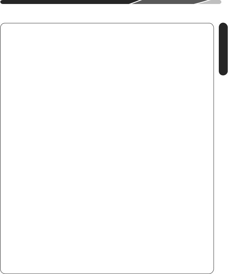
2.6 Shipping Strap Removal
Notice: Failure to remove strap prior to operation could result in increased internal tubing stress. Plastic strap can be cut off from the exterior of the unit and left inside of the unit.
2.7 Efficiency Testing Notice
For purposes of verifying or testing efficiency ratings, the test procedure in Title 10 APPENDIX M to Subpart B of Part 430 (Uniform Test Method for
Measuring the Energy Consumption of Central Air
Conditioners and Heat Pumps) and the clarifying provisions provided in the AHRI Operations
Manual 210/240 that were applicable at the date of manufacture should be used for test set up and performance.
2.8 Compressor
Break-In Notice
Prior to agency testing, the system must be run for 20 hours at 115ºF [46.1ºC] outdoor ambient
temperature with 80ºF [26.7ºC] dry bulb/75ºF [23.9ºC] wet bulb indoor ambient temperature to break the compressor in.
Information General
5
Specifications
3.0UNIT SPECIFICATIONS
3.1Model Number Nomenclature
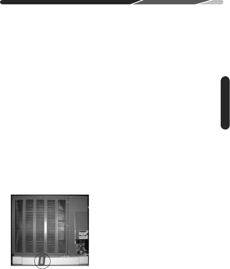
DR HP 14 A 24 A J 1 N A
MINOR SERIES
CONTROLS
Z N - NON-COMMUNICATING
TYPE
1 - SINGLE STAGE
VOLTAGE
J = 1 PH, 208-230/60
A = 1ST DESIGN
F = FRONT RETURN AHU
CAPACITY
18 = 18000 BTU/HR [5.28 kW]
24 = 24000 BTU/HR [7.03 kW]
30 = 30000 BTU/HR [8.79 kW]
36 = 36000 BTU/HR [10.55 kW]
42 = 42000 BTU/HR [12.31 kW]
48 = 48000 BTU/HR [14.07 kW]
60 = 60000 BTU/HR [17.58 kW]
A = 410a
B = Future Low GWP
14 SEER
AC = CONDENSING UNIT
HP = HEAT PUMP
BRAND
DR = DURASTAR
3.2 Available Models
DRHP14A18AJ1NA
DRHP14A18BJ1NA
DRHP14A24AJ1NA
DRHP14A30AJ1NA
DRHP14A36AJ1NA
DRHP14A42AJ1NA
DRHP14A48AJ1NA
DRHP14A60AJ1NA
6

3.0 UNIT SPECIFICATIONS


 3.3 Electrical and Physical Data
|
ELECTRICAL AND PHYSICAL DATA – 14 SEER |
|
|
|
|
|
|
|
|
|
|
|
||||||
|
|
|
|
|
|
|
|
|
|
|
|
|
|
|
|
|
|
|
|
|
|
|
ELECTRICAL DATA |
|
|
|
|
|
|
PHYSICAL DATA |
|
|
|
|
|||
|
Model |
|
Compressor |
|
|
|
Fuse or HACR |
|
Outdoor Coil |
|
Weight |
|
|
|||||
|
|
Fan Motor |
|
Minimum |
Circuit Breaker |
|
Refrig. |
|
|
|||||||||
|
Phase |
|
|
|
|
|
|
|
|
|
|
|
||||||
|
Number |
|
|
Full Load |
|
Circuit |
|
|
|
|
|
|
Per |
|
|
|
|
|
|
[-]P14 |
Frequency (Hz) |
Rated Load |
Locked |
|
|
|
Face Area |
|
|
|
|
|
|
||||
|
Amperes |
|
Ampacity |
|
|
|
|
Circuit |
|
|
|
|
||||||
|
Rotor |
|
Minimum |
Maximum |
No. |
CFM |
Net |
Shipping |
|
|
||||||||
|
|
Voltage (Volts) |
Amperes |
(FLA) |
|
Amperes |
Sq. Ft. |
Oz. [g]* |
|
|
||||||||
|
|
|
Amperes |
|
Amperes |
Amperes |
Rows |
[L/s] |
Lbs. [Kg] |
Lbs. [Kg] |
|
|
||||||
|
|
|
(RLA) |
|
|
|
[m2] |
|
|
|
||||||||
|
|
|
(LRA) |
|
|
|
|
|
|
|
|
|
|
|
|
|||
|
|
|
|
|
|
|
|
|
|
|
|
|
|
|
|
|
|
|
|
Rev. 02/22/2019 |
|
|
|
|
|
|
|
|
|
|
|
|
|
|
|
|
|
|
18 |
|
|
|
|
|
12/12 |
|
|
|
[1.03] |
|
|
|
|
|
|
|
|
1-60-208-230 |
9/9 |
48 |
0.5 |
|
15/15 |
20/20 |
11.06 |
1 |
1572 [742] |
79 [2240] |
145 [65.8] |
152 [68.9] |
|
|
|||
|
|
|
|
|
|
|
|
|
|
|
|
|
|
|
|
|
|
|
|
18B |
1-60-208-230 |
9/9 |
48 |
0.8 |
|
13/13 |
15/15 |
20/20 |
13.72 |
[1.27] |
1 |
2590 [1222] |
100 [2835] |
154 [69.9] |
164 [74.4] |
|
|
|
|
|
|
|
|
|
|
|
|
|
|
|
|
|
|
|
|
|
|
18F |
1-60-208-230 |
9/9 |
48 |
0.8 |
|
13/13 |
15/15 |
20/20 |
13.72 |
[1.27] |
1 |
2590 [1222] |
106 [3005] |
154 [69.9] |
164 [74.4] |
|
|
|
|
|
|
|
|
|
|
|
|
|
|
|
|
|
|
|
|
|
|
24A |
1-60-208-230 |
12.8/12.8 |
58.3 |
0.5 |
|
17/17 |
20/20 |
25/25 |
11.06 |
[1.03] |
1 |
2370 [1118] |
79 [2240] |
145 [65.8] |
152 [68.9] |
|
|
|
|
|
|
|
|
|
|
|
|
|
|
|
|
|
|
|
|
|
|
24F |
1-60-208-230 |
13.5/13.5 |
58.3 |
0.8 |
|
18/18 |
25/25 |
30/30 |
13.72 |
[1.27] |
1 |
2590 [1222] |
104 [2948] |
155 [70.3] |
165 [74.8] |
|
|
|
|
|
|
|
|
|
|
|
|
|
|
|
|
|
|
|
|
|
|
30A |
1-60-208-230 |
14.1/14.1 |
73 |
0.8 |
|
19/19 |
25/25 |
30/30 |
13.72 |
[1.27] |
1 |
2800 [1321] |
97 [2750] |
201 [91.2] |
208 [94.3] |
|
|
|
|
|
|
|
|
|
|
|
|
|
|
|
|
|
|
|
|
|
|
30F |
1-60-208-230 |
12.8/12.8 |
64 |
1.2 |
|
18/18 |
25/25 |
30/30 |
16.39 |
[1.52] |
1 |
2595 [1225] |
114 [3232] |
169 [76.7] |
181 [82.1] |
|
|
|
|
|
|
|
|
|
|
|
|
|
|
|
|
|
|
|
|
Specifications |
|
36 |
1-60-208-230 |
16.7/16.7 |
79 |
1.2 |
|
23/23 |
30/30 |
35/35 |
16.39 |
[1.52] |
1 |
3575 [1687] |
101 [2863] |
207 [93.9] |
214 [97.1] |
|
|
|
|
|
|
|
|
|
|
|
|
|
|
|
|
|
|
|
|
|
|
42 |
1-60-208-230 |
17.9/17.9 |
112 |
1.2 |
|
24/24 |
30/30 |
40/40 |
21.85 |
[2.03] |
1 |
3575 [1687] |
140 [3969] |
220 [99.8] |
227 [103.0] |
|
|
|
|
|
|
|
|
|
|
|
|
|
|
|
|
|
|
|
|
|
|
48 |
1-60-208-230 |
21.8/21.8 |
117 |
1.0 |
|
29/29 |
35/35 |
50/50 |
21.85 |
[2.03] |
1 |
3575 [1687] |
146 [4139] |
223.5 [101.4] |
230.5 [104.6] |
|
|
|
|
|
|
|
|
|
|
|
|
|
|
|
|
|
|
|
|
|
|
60 |
1-60-208-230 |
26.4/26.4 |
134 |
1.7 |
|
35/35 |
45/45 |
60/60 |
21.85 |
[2.03] |
2 |
3360 [1586] |
268 [7598] |
266.5 [120.9] |
273.5 [124.1] |
|
|
|
|
|
|
|
|
|
|
|
|
|
|
|
|
|
|
|
|
|
|
NOTES: |
|
|
|
|
|
|
|
|
|
|
|
|
|
|
|
|
|
|
*Factory charged for 15 ft. [4.6 m] of line set |
|
|
|
|
|
|
|
|
|
|
|
|
|
|
|||
|
|
|
|
|
|
|
|
|
|
|
|
|
|
|
|
|
|
|
7

3.0 UNIT SPECIFICATIONS
 3.3 Electrical and Physical Data (cont.)
DIMENSIONS |
w |
|
A-00008 |
L
Specifications |
H |
|
SEE DETAIL A
LIQUID
SERVICE
FITTING
TRUE SUCTION SERVICE PORT
2” 
[50.8 mm] 
BASERAIL*
*The 3-5 ton models do not feature a baserail.
DIMENSIONAL DATA
|
Model Number |
18, 24A |
18B, 18F, 24F, |
|
DRHP14 |
30A |
|
|
|
||
|
Height “H” (in.) [cm] |
261/4 [66.67] |
261/4 [66.67] |
|
Length “L” (in.) [cm] |
235/8 [60.0] |
275/8 [70.16] |
8 |
Width “W” (in.) [cm] |
235/8 [60.0] |
275/8 [70.16] |
|
|
|
AIR DISCHARGE: ALLOW
60” [152.4 cm] MINIMUM CLEARANCE.
AIR INLETS
(LOUVERED PANELS) ALLOW 6” [15.2 cm] MINIMUM CLEARANCE
SERVICE ACCESS
ALLOW 24” [61.0 cm]
NOTE: GRILLE APPEARANCE
MAY VARY.
VAPOR
SERVICE
FITTING
|
BASE PAN (BOTTOM VIEW) |
|
|
DO NOT OBSTRUCT DRAIN HOLES |
|
|
|
(SHADED). |
30F, 36 |
|
|
42, 48, 60 |
|
|
273/8 [69.53] |
353/8 [89.85] |
*NOTE: “H” dimension |
315/8 [80.32] |
315/8 [80.32] |
includes baserails and/ |
315/8 [80.32] |
315/8 [80.32] |
or basepan. |
|
||
4.0 INSTALLATION
 4.1 Tools and Refrigerant
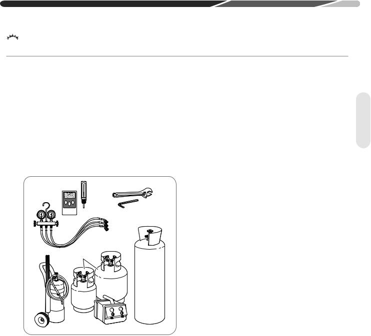
4.1.1 Tools Required for Installing and Servicing R-410A Models
Manifold Sets:
–Up to 800 PSIG [5,516 kPa] High-Side
–Up to 250 PSIG [1,724 kPa] Low-Side
–550 PSIG [3,792 kPa] Low-Side Retard
Manifold Hoses:
–Service Pressure Rating of 800 PSIG [5,516 kPa] Recovery Cylinders:
–400 PSIG [2,758 kPa] Pressure Rating
–Dept. of Transportation 4BA400 or BW400
Ambient and Tube
Thermometers  Crescent Wrench
Allen Wrench
Manifold |
Gauge |
Set |
Brazing |
Recovery |
Rods |
Cylinders |
Torch |
Reclaimer |
Nitrogen |
 CAUTION: R-410A systems operate at higher pressures than R-22 systems. Do not use R-22 service equipment or components on R-410A equipment.
4.1.2 Specifications of R-410A
Application: R-410A is not a drop-in replacement for R-22. Equipment designs must accommodate its higher pressures. It cannot be retrofitted into R-22 heat pumps.
Physical Properties: R-410A has an atmospheric boiling point of -62.9°F [-52.7°C] and its saturation pressure at 77°F [25°C] is 224.5 psig [1,548 kPa].
Composition: R-410A is a near-azeotropic mixture of 50% by weight difluoromethane (HFC-32) and 50% by weight pentafluoroethane (HFC-125).
Pressure: The pressure of R-410A is
approximately 60% (1.6 times) greater than R-22. Recovery and recycle equipment, pumps, hoses, and the like must have design pressure ratings appropriate for R-410A. Manifold sets need
to range up to 800 psig [5,516 kPa] high-side and 250 psig [1,724 kPa] low-side with a 550 psig [3,792 kPa] low-side retard. Hoses need to have a service pressure rating of 800 psig [,516 kPa].
Recovery cylinders need to have a 400 psig [2,758 kPa] service pressure rating, DOT 4BA400 or DOT BW400.
Combustibility: At pressures above 1 atmosphere, a mixture of R-410A and air can become combustible. R-410A and air should
never be mixed in tanks or supply lines or be allowed to accumulate in storage tanks.
Leak checking should never be done with a mixture of R-410A and air. Leak-checking can be performed safely with nitrogen or a mixture of R-410A and nitrogen.
4.1.3 Quick-Reference Guide for R-410A
•R-410A refrigerant operates at approximately
60% higher pressure (1.6 times) than R-22. Ensure that servicing equipment is designed to operate with R-410A.
•R-410A refrigerant cylinders are light rose in color.
•R-410A, as with other HFCs, is only compatible with POE oils.
•Vacuum pumps will not remove moisture from
POE oil used in R-410A systems.
•R-410A systems are to be charged with liquid refrigerants. Prior to March 1999, R-410A refrigerant cylinders had a dip tube. These cylinders should be kept upright for equipment charging. Post-March 1999 cylinders do not have a dip tube and should be inverted to ensure liquid charging of the equipment.
•Do not install a suction line filter drier in the liquid line.
•A factory-approved bi-flow liquid line filter drier
is shipped with every unit and must be installed in the liquid line at the time of installation. Only manufacturer-approved liquid line filter driers should be used. Filter driers must be rated for a working pressure of at least 600 psig [4,137 kPa]. The filter drier will only have adequate moisture-holding capacity if the system is properly evacuated.
•Desiccant (drying agent) must be compatible for
POE oils and R-410A refrigerant.
Tools
9
Location
4.0 INSTALLATION
 4.2 Choosing a Location
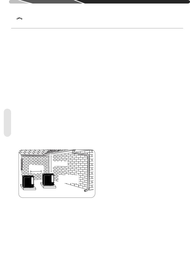
4.2.1 Allowable Clearances
12" [30.5 cm] to side intake louvers 24" [61.0 cm] to service access panels 60" [152.4 cm] vertical for fan discharge
If space limitations exist, the following clearances will have minimal impact to capacity and efficiency and are permitted:
Single-Unit Applications: Minimum of 6" [15.2 cm] to side intake louvers. Do not reduce the 60" [152.4 cm] for fan discharge or the 24" [61.0 cm] service clearances.
Multiple-Unit Applications: For units positioned next to each other, a minimum of 6" [15.2 cm] clearance between units is recommended for 1.5 and 2 ton models and 9" [22.9 cm] for 2.5 ton to 5 ton models. Do not reduce the 60" [152.4 cm] for fan discharge or the 24" [61.0 cm] service clearances.
IMPORTANT: Consult local and national building codes and ordinances for special installation requirements. Following location information will provide longer life and simplified servicing of the outdoor heat pump.
NOTICE: These units must be installed outdoors. No ductwork can be attached, or other modifications made, to the discharge grille.
Modifications will affect performance or operation.
ALLOW 60” [152.4 cm]
OF CLEARANCE
12” Min. (30.5 cm) 24” [61.0 CM] 

RECOMMENDED
AIR INLET LOUVERS ALLOW 6” [15.2 cm] Min. OF CLEARANCE ALL SIDES
12” [30.5 cm] RECOMMENDED
SERVICE PANELS/ |
|
INLET CONNECTIONS |
|
/ HIGH & LOW |
|
VOLTAGE ACCESS |
|
ALLOW 24” [ 61.0 cm] OF |
ST-A1226-143-00 |
|
4.2.2 Operational Issues Related to Unit Location
IMPORTANT: Locate the unit in a manner that will not prevent, impair, or
compromise the performance of other equipment installed in proximity to the unit. Maintain all required minimum distances to gas and electric meters, dryer vents, and exhaust and inlet openings. In the absence of national codes or manufacturers’ recommendations, local code recommendations and requirements will take precedence.
•Refrigerant piping and wiring should be properly sized and kept as short as possible to avoid capacity losses and increased operating costs.
•Locate the unit where water runoff will not create a problem with the equipment. Position the unit away from the drip edge of the roof whenever possible. Units are weatherized, but can be affected by the following:
•Water pouring into the unit from the junction of rooflines, without protective guttering. Large volumes of water entering the heat pump while in operation can impact fan blade or motor life, and coil damage may occur to a heat pump
if moisture cannot drain from the unit under freezing conditions.
•Freezing moisture or sleeting conditions can cause the cabinet to ice-over prematurely and prevent heat pump operation, requiring backup heat, which generally results in less economical operation It is highly recommended to switch the EcoNet™ Control Center or thermostat to the "Emergency Heat" mode during freezing rain or sleeting conditions to prevent damage to the outdoor coil from ice accumulating on the fan blade.
•Closely follow the clearance recommendations in section 4.2.1.
•24" [61.0 cm] to the service panel access
•60" [152.4 cm] above heat pump fan discharge
(unit top) to prevent recirculation
•6" [15.2 cm] to heat pump coil grille air inlets with 12" [30.5 cm] minimum recommended
10
4.0 INSTALLATION
 4.2 Choosing a Location (cont.)
4.2.3 Corrosive Environment
The metal parts of this unit may be subject to rust or deterioration if exposed to a corrosive environment. This oxidation could shorten the equipment’s useful life.
Corrosive elements include, but are not limited to, salt spray, fog or mist in seacoast areas, sulphur or chlorine from lawn watering systems, and various chemical contaminants from industries such as paper mills and petroleum refineries.
If the unit is to be installed in an area where contaminants are likely to be a problem, special attention should be given to the equipment location and exposure.
•Avoid having lawn sprinkler heads spray directly on the unit cabinet.
•In coastal areas, locate the unit on the side of the building away from the waterfront.
•Shielding provided by a fence or shrubs may give some protection, but cannot violate minimum airflow and service access clearances.
 WARNING: Disconnect all power to unit before starting maintenance. Failure to do so can cause electrical shock resulting in severe personal injury or death.
Regular maintenance will reduce the buildup of contaminants and help to protect the unit’s finish.
•Frequent washing of the cabinet, fan blade, and coil with fresh water will remove most of the salt or other contaminants that build up on the unit.
•A good liquid cleaner may be used several times a year to remove matter that will not wash off with water.
4.2.4 Customer Satisfaction
Issues
•The heat pump should be located away from the living, sleeping, and recreational spaces of the owner and those spaces on adjoining property.
•To prevent noise transmission, the mounting pad for the outdoor unit should not be connected to the structure and should be located a sufficient distance above grade to prevent ground water from entering the unit.
Location
 4.3 Mounting Unit
4.3.1 Unit Mounting Methods
The outdoor heat pump unit may be mounted in a number of ways. The most common method is on a ground mounted concrete or pre-fabricated pad. It can also be mounted on a ground or roof mounted metal frame, wooden frame, or 4” x
4” [10.2 cm x 10.2 cm] wooden stringers. It is extremely important to properly secure the unit to the pad or frame so it does not shift during high winds, seismic events, or other outside forces
to eliminate the possibility of a safety hazard or physical damage to the unit. Local codes in regions subject to frequent hurricanes and seismic events will dictate specific mounting requirements and must be followed. It is also important to elevate the heat pump in areas that receive a significant amount of snowfall so accumulated snow does not block the outdoor coil and interfere with drainage of water during the defrost cycle. Refer to Section 4.3.4 for typical ground snow levels for different regions of the USA.
4.3.2 High Wind and Seismic Tie-Down Methods
The manufacturer-approved/recommended method is a guide to securing equipment for wind and seismic loads. Other methods might provide the same result, but the manufacturer method is
the only one endorsed by the manufacturer for securing equipment where wind or earthquake damage can occur. Additional information is available on the manufacturer's website or from the wholesale distributor.
Mounting
11
Mounting
4.0 INSTALLATION
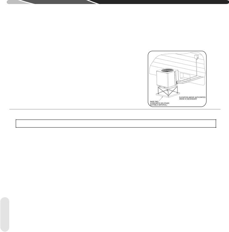
4.3.3 Elevating Unit
 WARNING: Secure an elevated unit and its elevating stand in order to prevent tipping. Failure to do so may result in severe personal injury or death.
If elevating the heat pump, either on a flat roof or on a slab, observe the following guidelines.
•The bottom of the basepan has receptacles for 4" [10.2 cm] schedule 40 PVC pipe that can be cut to length and used as risers for slab applications.
•If elevating a unit on a flat roof, use 4" x 4" [10.2 cm x 10.2 cm] or equivalent stringers positioned to distribute unit weight evenly and prevent noise and vibration.
•Where snowfall is anticipated, raise the unit above the base pad to prevent ice buildup and coil damage. Mount the unit high enough to be above the average accumulated area snowfall. See “Ground Snow Depth” chart below for representative snow depths.
NOTICE: Do not block drain openings on bottom of unit.
•If unit must be elevated because of anticipated snowfall, secure unit and elevating stand such that unit and/or stand will not tip over or fall off. Keep in mind that someone may try to climb on unit.
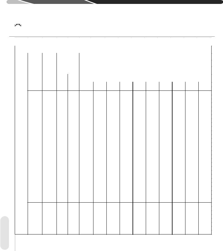
4.3.4 Ground Snow Depth Table
GROUND SNOW DEPTH – INCHES
ALABAMA |
|
INDIANA |
|
MINNESOTA |
|
NEW MEXICO |
|
PENNSYLVANIA |
|
VIRGINIA |
|
Huntsville |
7 |
Evansville |
12 |
Duluth |
64 |
Albuquerque |
4 |
Allentown |
23 |
Dulles Airport |
19 |
ARIZONA |
|
Fort Wayne |
17 |
International Falls |
43 |
Clayton |
10 |
Erie |
19 |
Lynchburg |
16 |
Flagstaff |
48 |
Indianapolis |
21 |
Minneapolis/St. Paul |
50 |
Roswell |
8 |
Harrisburg |
23 |
National Airport |
18 |
Prescott |
3 |
South Bend |
44 |
Rochester |
50 |
NEW YORK |
|
Philadelphia |
16 |
Norfolk |
9 |
Winslow |
7 |
IOWA |
|
St. Cloud |
53 |
Albany |
25 |
Pittsburgh |
22 |
Richmond |
12 |
ARKANSAS |
|
Burlington |
17 |
MISSISSIPPI |
|
Binghamton |
35 |
Scranton |
16 |
Roanoke |
17 |
Fort Smith |
5 |
Des Moines |
22 |
Jackson |
3 |
Buffalo |
42 |
Williamsport |
20 |
WASHINGTON |
|
Little Rock |
6 |
Dubuque |
38 |
MISSOURI |
|
NYC – Kennedy Airport |
18 |
RHODE ISLAND |
|
Olympia |
24 |
CALIFORNIA |
|
Sioux City |
33 |
Columbia |
21 |
NYC – LaGuardia Airport 18 |
Providence |
21 |
Quillayute |
24 |
|
Blue Canyon |
25 |
Waterloo |
36 |
Kansas City |
18 |
Rochester |
38 |
SOUTH CAROLINA |
Seattle-Tacoma |
14 |
|
Mt. Shasta |
69 |
KANSAS |
|
St. Louis |
16 |
Syracuse |
35 |
Columbia |
12 |
Spokane |
41 |
COLORADO |
|
Concordia |
23 |
Springšeld |
14 |
NORTH CAROLINA |
|
Greenville |
4 |
Stampede Pass |
51 |
Alamosa |
15 |
Dodge City |
12 |
MONTANA |
|
Asheville |
12 |
SOUTH DAKOTA |
|
Yakima |
25 |
Colorado Springs 14 |
Goodland |
14 |
Billings |
17 |
Cape Hattaras |
5 |
Aberdeen |
42 |
WEST VIRGINIA |
|
|
Denver |
15 |
Topeka |
19 |
Glasgow |
17 |
Charlotte |
10 |
Huron |
43 |
Beckley |
51 |
Grand Junction |
16 |
Wichita |
11 |
Great Falls |
16 |
Greensboro |
11 |
Rapid City |
14 |
Charleston |
20 |
Pueblo |
7 |
KENTUCKY |
|
Havre |
24 |
Raleigh-Durham |
10 |
Sioux Falls |
38 |
Elkins |
21 |
CONNECTICUT |
|
Covington |
12 |
Helena |
18 |
Wilmington |
9 |
TENNESSEE |
|
Huntington |
15 |
Bridgeport |
23 |
Lexington |
12 |
Kalispell |
53 |
Winston-Salem |
17 |
Bristol |
8 |
WISCONSIN |
|
Hartford |
29 |
Louisville |
11 |
Missoula |
23 |
NORTH DAKOTA |
|
Chattanooga |
6 |
Green Bay |
36 |
New Haven |
15 |
MAINE |
|
NEBRASKA |
|
Bismarck |
25 |
Knoxville |
8 |
La Crosse |
32 |
DELAWARE |
|
Caribou |
100 |
Grand Island |
30 |
Fargo |
34 |
Memphis |
5 |
Madison |
32 |
Wilmington |
13 |
Portland |
62 |
Lincoln |
20 |
Williston |
25 |
Nashville |
8 |
Milwaukee |
32 |
GEORGIA |
|
MARYLAND |
|
Norfolk |
29 |
OHIO |
|
TEXAS |
|
WYOMING |
|
Athens |
5 |
Baltimore |
17 |
North Platte |
15 |
Akron-Canton |
15 |
Abilene |
6 |
Casper |
10 |
Macon |
8 |
MASSACHUSETTS |
Omaha |
20 |
Cleveland |
16 |
Amarillo |
10 |
Cheyenne |
15 |
|
IDAHO |
|
Boston |
30 |
Scottsbluff |
11 |
Columbus |
10 |
Dallas |
3 |
Lander |
20 |
Boise |
6 |
Nantucket |
18 |
Valentine |
22 |
Dayton |
11 |
El Paso |
5 |
Sheridan |
25 |
Lewiston |
9 |
Worcester |
35 |
NEVADA |
|
Mansšeld |
17 |
Fort Worth |
6 |
|
|
Pocatello |
7 |
MICHIGAN |
|
Elko |
20 |
Toledo Express |
8 |
Lubbock |
10 |
|
|
ILLINOIS |
|
Alpena |
53 |
Ely |
9 |
Youngstown |
12 |
Midland |
2 |
|
|
Chicago O’Hare |
18 |
Detroit City |
9 |
Reno |
11 |
OKLAHOMA |
|
San Antonio |
3 |
|
|
Chicago |
22 |
Detroit Airport |
17 |
Winnemucca |
6 |
Oklahoma City |
5 |
Wichita Falls |
5 |
|
|
Moline |
17 |
Detroit – Willow Run 21 |
NEW HAMPSHIRE |
|
Tulsa |
8 |
UTAH |
|
|
|
|
Peoria |
16 |
Flint |
28 |
Concord |
66 |
OREGON |
|
Milford |
16 |
|
|
Rockford |
25 |
Grand Rapids |
37 |
NEW JERSEY |
|
Burns City |
24 |
Salt Lake City |
8 |
|
|
Springšeld |
23 |
Houghton Lake |
56 |
Atlantic City |
11 |
Eugene |
17 |
Wendover |
3 |
|
|
|
|
Lansing |
42 |
Newark |
15 |
Medford |
8 |
VERMONT |
|
|
|
|
|
Marquette |
53 |
|
|
Pendleton |
11 |
Burlington |
37 |
|
|
|
|
Muskegon |
43 |
|
|
Portland |
10 |
|
|
|
|
|
|
Sault Ste. Marie |
80 |
|
|
Salem |
7 |
|
|
|
|
|
NOTICE: Local records and experience must be considered when establishing the unit installation height. There is a 2% probability that |
12 |
the ground snow depth shown in this table will be exceeded annually. Drifts have not been considered. This data represents 184 |
National Weather Service locations at which measurements are made and assumes a nationwide snow density of 12 lb./ft.3 |

4.0 INSTALLATION
 4.4 Refrigerant Line Set Selection
4.4.1 Replacing Existing Systems
To prevent failure of a new unit, the existing line set must be correctly sized for the new unit and must be cleaned or replaced. Care must be taken so the expansion device is not plugged. For new and replacement units, a liquid line filter drier must be installed and the line set must be properly sized. Test the oil for acid. If it tests positive for acid, a suction line filter drier is mandatory.
IMPORTANT: When replacing an R-22 unit with an R-410A unit, either replace the line set or ensure that residual mineral oil is
drained from existing lines including oil trapped in low spots.
4.4.2 Line Set Length and Fitting Losses
Refrigerant tubing is measured in terms of actual length and equivalent length. Actual length is used for refrigerant charge applications. Equivalent length takes into account pressure losses from
tubing length, fittings, vertical separation, accessories, and filter driers. The table below references commonly used equivalent lengths.
|
|
|
|
Table 1 |
|
|
|
|
|
|
|
|
|
|
|
|
|
|
|
|
|
|
|
|
|
|
|
|
ƋƵŝǀĂůĞŶƚ >ĞŶŐƚŚ ĨŽƌ &ŝƚƚŝŶŐƐ ;Ĩƚ ŵ |
|
|
|
|
|
||||
|
|
ϵϬΣ ^ŚŽƌƚ |
ϵϬΣ >ŽŶŐ |
|
|
|
|
|
|
|
|
|
|
>ŝŶĞ ^ŝnjĞ |
ZĂĚŝƵƐ |
ZĂĚŝƵƐ |
ϰϱΣ |
|
^ŽůĞŶŽŝĚ |
|
ŚĞĐŬ |
^ŝƚĞ |
&ŝůƚĞƌ |
|
|
|
;ŝŶ ŵŵ |
ůďŽǁ |
ůďŽǁ |
ůďŽǁ |
|
sĂůǀĞ |
|
sĂůǀĞ |
'ůĂƐƐ |
ƌŝĞƌ |
|
|
|
ϯͬϴ ϵ͘ϱϯ |
ϭ͘ϯ Ϭ͘ϰϬ |
Ϭ͘ϴ Ϭ͘Ϯϰ |
Ϭ͘ϯ Ϭ͘Ϭϵ |
|
ϲ ϭ͘ϴϯ |
|
ϰ ϭ͘ϮϮ |
Ϭ͘ϰ Ϭ͘ϭϮ |
ϲ ϭ͘ϴϯ |
|
|
|
ϭͬϮ ϭϮ͘ϳϭ |
ϭ͘ϰ Ϭ͘ϰϯ |
Ϭ͘ϵ Ϭ͘Ϯϳ |
Ϭ͘ϰ Ϭ͘ϭϮ |
|
ϵ Ϯ͘ϳϰ |
|
ϱ ϭ͘ϱϮ |
Ϭ͘ϲ Ϭ͘ϭϴ |
ϲ ϭ͘ϴϯ |
|
|
|
ϱͬϴ ϭϱ͘ϴϴ |
ϭ͘ϱ Ϭ͘ϰϲ |
ϭ Ϭ͘ϯϬ |
Ϭ͘ϱ Ϭ͘ϭϱ |
|
ϭϮ ϯ͘ϲϲ |
|
ϲ ϭ͘ϴϯ |
Ϭ͘ϴ Ϭ͘Ϯϰ |
ϲ ϭ͘ϴϯ |
|
Installation |
|
ϯͬϰ ϭϵ͘Ϭϱ |
ϭ͘ϵ Ϭ͘ϱϴ |
ϭ͘ϯ Ϭ͘ϰϬ |
Ϭ͘ϲ Ϭ͘ϭϴ |
|
ϭϰ ϰ͘Ϯϳ |
|
ϳ Ϯ͘ϭϯ |
Ϭ͘ϵ Ϭ͘Ϯϳ |
ϲ ϭ͘ϴϯ |
|
|
|
|
|
|
|
||||||||
|
ϳͬϴ ϮϮ͘Ϯϯ |
Ϯ͘ϯ Ϭ͘ϳϬ |
ϭ͘ϱ Ϭ͘ϰϲ |
Ϭ͘ϳ Ϭ͘Ϯϭ |
|
ϭϱ ϰ͘ϱϳ |
|
ϴ Ϯ͘ϰϰ |
ϭ Ϭ͘ϯϬ |
ϲ ϭ͘ϴϯ |
|
|
|
ϭ ϭͬϴ Ϯϴ͘ϱϴ |
Ϯ͘ϳ Ϭ͘ϴϮ |
ϭ͘ϴ Ϭ͘ϱϱ |
Ϭ͘ϵ Ϭ͘Ϯϳ |
|
ϮϮ ϲ͘ϳϭ |
|
ϭϮ ϯ͘ϲϲ |
ϭ͘ϱ Ϭ͘ϰϲ |
ϲ ϭ͘ϴϯ |
|
|
|
|
|
|
|
|
|
|
|
|
|
|
|
4.4.3 Liquid Line Selection
The purpose of the liquid line is to transport warm sub-cooled liquid refrigerant between the outdoor unit to the indoor unit. It is important not to allow the refrigerant to flash into superheated vapor prior to the expansion device of the indoor or outdoor coil. The flashing of refrigerant can occur for the following reasons:
•Low refrigerant charge
•Improperly selected liquid line size
•Absorption of heat prior to expansion device
•Excessive vertical separation between the outdoor unit and indoor coil
•Restricted liquid line or filter drier
•Kinked liquid line
The total pressure drop allowed for the liquid line is 50 PSI [345 kPa]. The procedure for selecting the proper liquid line is as follows:
•Measure the total amount of vertical separation between the outdoor unit and indoor coil.
•Measure the linear length of liquid line needed.
•Add all of the equivalent lengths associated with any fittings or accessories using Table 1 above.
•Add the linear length to the total fitting equivalent length. This will equal your total equivalent line length.
•Reference Table 2 to verify the calculated equivalent length is acceptable with the required vertical separation and diameter of liquid line.
13
Tubing
4.0 INSTALLATION
 4.4 Refrigerant Line Set Selection (cont.)
dĂďůĞϮ ͗ ZĞĨƌŝŐĞƌĂŶƚ>ŝŶĞ^ŝnjŝŶŐ ŚĂƌƚ; ŶŐůŝƐŚhŶŝƚƐ
|
|
|
|
|
|
ϭϰ ^ Z ^ŝŶŐůĞ ^ƚĂŐĞ,ĞĂƚ WƵŵƉƐ |
|
|
|
|
|
|||||||
|
|
|
|
hƐĞ>ŽŶŐ>ŝŶĞ |
|
|
|
|
KƵƚĚŽŽƌhŶŝƚ Ks Žƌ >Kt/ŶĚŽŽƌhŶŝƚ |
|
|
|
|
|||||
|
|
|
|
'ƵŝĚĞůŝŶĞƐĨŽƌ |
|
|
|
|
|
|
|
|
||||||
|
|
|
|
|
|
|
|
|
|
|
|
|
|
|
|
|
||
|
ůůŽǁĂďůĞ |
ůůŽǁĂďůĞ |
>ŝŶĞĂƌ>ŝŶĞ |
|
|
|
|
|
ƋƵŝǀĂůĞŶƚ>ĞŶŐƚŚ;&ĞĞƚ |
|
|
|
|
|
||||
hŶŝƚ^ŝnjĞ |
>ĞŶŐƚŚƐ'ƌĞĂƚĞƌ |
|
|
|
|
|
|
|
|
|
|
|||||||
>ŝƋƵŝĚ>ŝŶĞ |
sĂƉŽƌ>ŝŶĞ |
dŚĂŶ^ŚŽǁŶ |
фϮϱ |
Ϯϲ ϱϬ |
ϱϭ ϳϱ |
|
ϳϲ ϭϬϬ |
|
ϭϬϭ ϭϮϱ |
ϭϮϲ ϭϱϬ |
ϭϱϭ ϭϳϱ |
ϭϳϲ ϮϬϬ |
ϮϬϭ ϮϮϱ |
ϮϮϲ ϮϱϬ |
||||
|
|
^ŝnjĞ |
^ŝnjĞ |
ĞůŽǁ;&ĞĞƚ |
|
|
||||||||||||
|
|
|
|
|
|
|
|
|
|
|
|
|
|
|
||||
|
|
|
|
Wϭϰ |
Wϭϰ |
|
|
|
DĂdžŝŵƵŵsĞƌƟĐĂů^ĞƉĂƌĂƟŽŶͬ ĂƉĂĐŝƚLJDƵůƟƉůŝĞƌ |
|
|
|
|
|||||
|
|
|
|
|
|
|
|
|
|
|
|
|
|
|
|
|
|
|
|
|
ϭͬϰΗ |
ϱͬϴΗ |
ŶͬĂ |
ŶͬĂ |
Ϯϱͬϭ͘ϬϬ |
ϱϬͬϬ͘ϵϵ |
ϲϮͬϬ͘ϵϴ |
|
ϰϯͬϬ͘ϵϴ |
|
ϮϰͬϬ͘ϵϳ |
ϱͬϬ͘ϵϳ |
EZ |
EZ |
EZ |
EZ |
|
|
|
ϱͬϭϲΗ |
ϱͬϴΗ |
ϭϵϱ |
ϭϰϵ |
Ϯϱͬϭ͘ϬϬ |
ϱϬͬϬ͘ϵϵ |
ϳϱͬϬ͘ϵϴ |
|
ϵϴͬϬ͘ϵϴ |
|
ϵϯͬϬ͘ϵϳ |
ϴϴͬϬ͘ϵϳ |
ϴϯͬϬ͘ϵϲ |
ϳϴͬϬ͘ϵϲ |
ϳϯͬϬ͘ϵϱ |
ϲϴͬϬ͘ϵϰ |
|
ϭ͘ϱdŽŶ |
ϱͬϴΗ |
ϭϯϬ |
ϭϬϰ |
Ϯϱͬϭ͘ϬϬ |
ϱϬͬϬ͘ϵϵ |
ϳϱͬϬ͘ϵϴ |
|
ϭϬϬͬϬ͘ϵϴ |
|
ϭϬϬͬϬ͘ϵϳ ϭϬϬͬϬ͘ϵϳ |
ϭϬϬͬϬ͘ϵϲ |
ϭϬϬͬϬ͘ϵϲ |
ϭϬϬͬϬ͘ϵϱ |
ϭϬϬͬϬ͘ϵϰ |
|
|||
Ύ^ |
|
ϯͬϴΗ |
|
|
|
|||||||||||||
|
ϭͬϰΗ |
ϯͬϰΗΎ |
ŶͬĂ |
ŶͬĂ |
Ϯϱͬϭ͘ϬϬ |
ϱϬͬϭ͘ϬϬ |
ϲϮͬϬ͘ϵϵ |
|
ϰϯͬϬ͘ϵϵ |
|
ϮϰͬϬ͘ϵϵ |
ϱͬϬ͘ϵϵ |
EZ |
EZ |
EZ |
EZ |
|
|
EKd ϯ |
|
|
|
|||||||||||||||
|
ϱͬϭϲΗ |
ϯͬϰΗΎ |
ϭϵϱ |
ϭϰϵ |
Ϯϱͬϭ͘ϬϬ |
ϱϬͬϭ͘ϬϬ |
ϳϱͬϬ͘ϵϵ |
|
ϵϴͬϬ͘ϵϵ |
|
ϵϯͬϬ͘ϵϵ |
ϴϴͬϬ͘ϵϵ |
ϴϯͬϬ͘ϵϵ |
ϳϴͬϬ͘ϵϴ |
ϳϯͬϬ͘ϵϴ |
ϲϴͬϬ͘ϵϴ |
|
|
|
|
ϯͬϴΗ |
ϯͬϰΗΎ |
ϭϯϬ |
ϭϬϰ |
Ϯϱͬϭ͘ϬϬ |
ϱϬͬϭ͘ϬϬ |
ϳϱͬϭ͘ϬϬ |
|
ϭϬϬͬϬ͘ϵϵ |
|
ϭϬϬͬϬ͘ϵϵ |
ϭϬϬͬϬ͘ϵϵ |
ϭϬϬͬϬ͘ϵϵ |
ϭϬϬͬϬ͘ϵϴ |
ϭϬϬͬϬ͘ϵϴ |
ϭϬϬͬϬ͘ϵϴ |
|
|
|
ϭͬϰΗ |
ϱͬϴΗ |
ŶͬĂ |
ŶͬĂ |
ϮϱͬϬ͘ϵϵ |
ϱϬͬϬ͘ϵϴ |
ϮϭͬϬ͘ϵϳ |
|
EZ |
|
EZ |
EZ |
EZ |
EZ |
EZ |
EZ |
|
|
|
ϱͬϭϲΗ |
ϱͬϴΗ |
ϭϵϱ |
ŶͬĂ |
ϮϱͬϬ͘ϵϵ |
ϱϬͬϬ͘ϵϴ |
ϳϱͬϬ͘ϵϳ |
|
ϴϳͬϬ͘ϵϲ |
|
ϳϳͬϬ͘ϵϱ |
ϲϵͬϬ͘ϵϰ |
ϲϭͬϬ͘ϵϯ |
ϱϯͬϬ͘ϵϮ |
ϰϱͬϬ͘ϵϭ |
ϯϳͬϬ͘ϵϬ |
|
ϮdŽŶ |
|
ϯͬϴΗ |
ϱͬϴΗ |
ϭϯϬ |
ŶͬĂ |
ϮϱͬϬ͘ϵϵ |
ϱϬͬϬ͘ϵϴ |
ϳϱͬϬ͘ϵϳ |
|
ϭϬϬͬϬ͘ϵϲ |
|
ϭϬϬͬϬ͘ϵϱ |
ϭϬϬͬϬ͘ϵϰ |
ϵϴͬϬ͘ϵϯ |
ϵϱͬϬ͘ϵϮ |
ϵϯͬϬ͘ϵϭ |
ϵϬͬϬ͘ϵϬ |
|
|
ϭͬϰΗ |
ϯͬϰΗ |
ŶͬĂ |
ŶͬĂ |
Ϯϱͬϭ͘ϬϬ |
ϱϬͬϭ͘ϬϬ |
ϮϭͬϬ͘ϵϵ |
|
EZ |
|
EZ |
EZ |
EZ |
EZ |
EZ |
EZ |
||
|
|
|
|
|||||||||||||||
|
|
ϱͬϭϲΗ |
ϯͬϰΗ |
ϭϵϱ |
ŶͬĂ |
Ϯϱͬϭ͘ϬϬ |
ϱϬͬϭ͘ϬϬ |
ϳϱͬϬ͘ϵϵ |
|
ϴϳͬϬ͘ϵϵ |
|
ϳϳͬϬ͘ϵϴ |
ϲϵͬϬ͘ϵϴ |
ϲϭͬϬ͘ϵϴ |
ϱϯͬϬ͘ϵϳ |
ϰϱͬϬ͘ϵϳ |
ϯϳͬϬ͘ϵϲ |
|
|
|
ϯͬϴΗ |
ϯͬϰΗ |
ϭϯϬ |
ŶͬĂ |
Ϯϱͬϭ͘ϬϬ |
ϱϬͬϭ͘ϬϬ |
ϳϱͬϬ͘ϵϵ |
|
ϭϬϬͬϬ͘ϵϵ |
|
ϭϬϬͬϬ͘ϵϴ |
ϭϬϬͬϬ͘ϵϴ |
ϵϴͬϬ͘ϵϴ |
ϵϱͬϬ͘ϵϳ |
ϵϯͬϬ͘ϵϳ |
ϵϬͬϬ͘ϵϲ |
|
|
|
ϱͬϭϲΗ |
ϱͬϴΗ |
ϭϱϬ |
ŶͬĂ |
ϮϱͬϬ͘ϵϵ |
ϱϬͬϬ͘ϵϴ |
ϳϱͬϬ͘ϵϲ |
|
ϳϬͬϬ͘ϵϰ |
|
ϱϵͬϬ͘ϵϯ |
ϰϴͬϬ͘ϵϭ |
ϯϲͬϬ͘ϵϬ |
EZ |
EZ |
EZ |
|
Ϯ͘ϱdŽŶ |
|
ϯͬϴΗ |
ϱͬϴΗ |
ϭϬϬ |
ŶͬĂ |
ϮϱͬϬ͘ϵϵ |
ϱϬͬϬ͘ϵϴ |
ϳϱͬϬ͘ϵϲ |
|
ϭϬϬͬϬ͘ϵϰ |
|
ϵϴͬϬ͘ϵϯ |
ϵϰͬϬ͘ϵϭ |
ϵϬͬϬ͘ϵϬ |
EZ |
EZ |
EZ |
|
|
ϱͬϭϲΗ |
ϯͬϰΗ |
ϭϱϬ |
ŶͬĂ |
Ϯϱͬϭ͘ϬϬ |
ϱϬͬϬ͘ϵϵ |
ϳϱͬϬ͘ϵϵ |
|
ϳϬͬϬ͘ϵϴ |
|
ϱϵͬϬ͘ϵϴ |
ϰϴͬϬ͘ϵϳ |
ϯϲͬϬ͘ϵϲ |
ϮϱͬϬ͘ϵϲ |
ϭϯͬϬ͘ϵϱ |
EZ |
||
|
|
|
|
|||||||||||||||
|
|
ϯͬϴΗ |
ϯͬϰΗ |
ϭϬϬ |
ŶͬĂ |
Ϯϱͬϭ͘ϬϬ |
ϱϬͬϬ͘ϵϵ |
ϳϱͬϬ͘ϵϵ |
|
ϭϬϬͬϬ͘ϵϴ |
|
ϵϴͬϬ͘ϵϴ |
ϵϰͬϬ͘ϵϳ |
ϵϬͬϬ͘ϵϲ |
ϴϲͬϬ͘ϵϲ |
ϴϮͬϬ͘ϵϱ |
ϳϴͬϬ͘ϵϱ |
|
|
|
ϱͬϭϲΗ |
ϱͬϴΗ |
ŶͬĂ |
ŶͬĂ |
ϮϱͬϬ͘ϵϵ |
ϱϬͬϬ͘ϵϳ |
ϲϲͬϬ͘ϵϰ |
|
ϰϵͬϬ͘ϵϮ |
|
ϯϮͬϬ͘ϵϬ |
EZ |
EZ |
EZ |
EZ |
EZ |
|
|
|
ϯͬϴΗ |
ϱͬϴΗ |
ϵϯ |
ŶͬĂ |
ϮϱͬϬ͘ϵϵ |
ϱϬͬϬ͘ϵϳ |
ϳϱͬϬ͘ϵϰ |
|
ϵϱͬϬ͘ϵϮ |
|
ϴϵͬϬ͘ϵϬ |
EZ |
EZ |
EZ |
EZ |
EZ |
|
|
|
ϱͬϭϲΗ |
ϯͬϰΗ |
ϭϰϬ |
ŶͬĂ |
Ϯϱͬϭ͘ϬϬ |
ϱϬͬϬ͘ϵϵ |
ϲϲͬϬ͘ϵϴ |
|
ϰϵͬϬ͘ϵϴ |
|
ϯϮͬϬ͘ϵϳ |
ϭϱͬϬ͘ϵϲ |
EZ |
EZ |
EZ |
EZ |
|
ϯdŽŶ |
|
ϯͬϴΗ |
ϯͬϰΗ |
ϵϯ |
ŶͬĂ |
Ϯϱͬϭ͘ϬϬ |
ϱϬͬϬ͘ϵϵ |
ϳϱͬϬ͘ϵϴ |
|
ϵϱͬϬ͘ϵϴ |
|
ϴϵͬϬ͘ϵϳ |
ϴϰͬϬ͘ϵϲ |
ϳϴͬϬ͘ϵϱ |
ϳϮͬϬ͘ϵϰ |
ϲϳͬϬ͘ϵϯ |
ϲϭͬϬ͘ϵϯ |
|
|
ϭͬϮΗ |
ϯͬϰΗ |
ϰϳ |
ŶͬĂ |
Ϯϱͬϭ͘ϬϬ |
ϱϬͬϬ͘ϵϵ |
ϳϱͬϬ͘ϵϴ |
|
ϭϬϬͬϬ͘ϵϴ |
|
ϭϬϬͬϬ͘ϵϳ |
ϭϬϬͬϬ͘ϵϲ |
ϭϬϬͬϬ͘ϵϱ |
ϭϬϬͬϬ͘ϵϰ |
ϭϬϬͬϬ͘ϵϯ |
ϭϬϬͬϬ͘ϵϯ |
||
|
|
|
|
|||||||||||||||
|
|
ϱͬϭϲΗ |
ϳͬϴΗ |
ϭϰϬ |
ŶͬĂ |
Ϯϱͬϭ͘ϬϬ |
ϱϬͬϭ͘ϬϬ |
ϲϲͬϭ͘ϬϬ |
|
ϰϵͬϬ͘ϵϵ |
|
ϯϮͬϬ͘ϵϵ |
ϭϱͬϬ͘ϵϵ |
EZ |
EZ |
EZ |
EZ |
|
|
|
ϯͬϴΗ |
ϳͬϴΗ |
ϵϯ |
ŶͬĂ |
Ϯϱͬϭ͘ϬϬ |
ϱϬͬϭ͘ϬϬ |
ϳϱͬϭ͘ϬϬ |
|
ϵϱͬϬ͘ϵϵ |
|
ϴϵͬϬ͘ϵϵ |
ϴϰͬϬ͘ϵϵ |
ϳϴͬϬ͘ϵϴ |
ϳϮͬϬ͘ϵϴ |
ϲϳͬϬ͘ϵϴ |
ϲϭͬϬ͘ϵϳ |
|
|
|
ϭͬϮΗ |
ϳͬϴΗ |
ϰϳ |
ŶͬĂ |
Ϯϱͬϭ͘ϬϬ |
ϱϬͬϭ͘ϬϬ |
ϳϱͬϭ͘ϬϬ |
|
ϭϬϬͬϬ͘ϵϵ |
|
ϭϬϬͬϬ͘ϵϵ ϭϬϬͬϬ͘ϵϵ |
ϭϬϬͬϬ͘ϵϴ |
ϭϬϬͬϬ͘ϵϴ |
ϭϬϬͬϬ͘ϵϴ |
ϭϬϬͬϬ͘ϵϳ |
|
|
|
|
ϯͬϴΗ |
ϯͬϰΗ |
ϵϮ |
ŶͬĂ |
ϮϱͬϬ͘ϵϵ |
ϱϬͬϬ͘ϵϴ |
ϳϱͬϬ͘ϵϳ |
|
ϴϴͬϬ͘ϵϲ |
|
ϴϬͬϬ͘ϵϱ |
ϳϮͬϬ͘ϵϰ |
ϲϱͬϬ͘ϵϮ |
ϱϳͬϬ͘ϵϭ |
ϰϵͬϬ͘ϵϬ |
EZ |
|
ϯ͘ϱdŽŶ |
|
ϭͬϮΗ |
ϯͬϰΗ |
ϰϲ |
ŶͬĂ |
ϮϱͬϬ͘ϵϵ |
ϱϬͬϬ͘ϵϴ |
ϳϱͬϬ͘ϵϳ |
|
ϭϬϬͬϬ͘ϵϲ |
|
ϭϬϬͬϬ͘ϵϱ |
ϭϬϬͬϬ͘ϵϰ |
ϭϬϬͬϬ͘ϵϮ |
ϭϬϬͬϬ͘ϵϭ |
ϭϬϬͬϬ͘ϵϬ |
EZ |
|
|
ϯͬϴΗ |
ϳͬϴΗ |
ϵϮ |
ŶͬĂ |
Ϯϱͬϭ͘ϬϬ |
ϱϬͬϭ͘ϬϬ |
ϳϱͬϬ͘ϵϵ |
|
ϴϴͬϬ͘ϵϵ |
|
ϴϬͬϬ͘ϵϵ |
ϳϮͬϬ͘ϵϴ |
ϲϱͬϬ͘ϵϳ |
ϱϳͬϬ͘ϵϳ |
ϰϵͬϬ͘ϵϲ |
ϰϮͬϬ͘ϵϲ |
||
|
|
|
|
|||||||||||||||
|
|
ϭͬϮΗ |
ϳͬϴΗ |
ϰϲ |
ŶͬĂ |
Ϯϱͬϭ͘ϬϬ |
ϱϬͬϭ͘ϬϬ |
ϳϱͬϬ͘ϵϵ |
|
ϭϬϬͬϬ͘ϵϵ |
|
ϭϬϬͬϬ͘ϵϵ ϭϬϬͬϬ͘ϵϴ |
ϭϬϬͬϬ͘ϵϳ |
ϭϬϬͬϬ͘ϵϳ |
ϭϬϬͬϬ͘ϵϲ |
ϭϬϬͬϬ͘ϵϲ |
|
|
|
|
ϯͬϴΗ |
ϯͬϰΗ |
ϴϮ |
ŶͬĂ |
ϮϱͬϬ͘ϵϵ |
ϱϬͬϬ͘ϵϴ |
ϳϱͬϬ͘ϵϲ |
|
ϳϳͬϬ͘ϵϱ |
|
ϲϳͬϬ͘ϵϯ |
ϱϳͬϬ͘ϵϮ |
ϰϲͬϬ͘ϵϭ |
EZ |
EZ |
EZ |
|
ϰdŽŶ |
ϭͬϮΗ |
ϯͬϰΗ |
ϰϭ |
ŶͬĂ |
ϮϱͬϬ͘ϵϵ |
ϱϬͬϬ͘ϵϴ |
ϳϱͬϬ͘ϵϲ |
|
ϭϬϬͬϬ͘ϵϱ |
|
ϭϬϬͬϬ͘ϵϯ ϭϬϬͬϬ͘ϵϮ |
ϭϬϬͬϬ͘ϵϭ |
EZ |
EZ |
EZ |
|
||
ϯͬϴΗ |
ϳͬϴΗ |
ϴϮ |
ŶͬĂ |
Ϯϱͬϭ͘ϬϬ |
ϱϬͬϬ͘ϵϵ |
ϳϱͬϬ͘ϵϵ |
|
ϳϳͬϬ͘ϵϴ |
|
ϲϳͬϬ͘ϵϳ |
ϱϳͬϬ͘ϵϳ |
ϰϲͬϬ͘ϵϲ |
ϯϲͬϬ͘ϵϲ |
ϮϲͬϬ͘ϵϱ |
ϭϱͬϬ͘ϵϱ |
|||
|
|
|
|
|||||||||||||||
|
|
ϭͬϮΗ |
ϳͬϴΗ |
ϰϭ |
ŶͬĂ |
Ϯϱͬϭ͘ϬϬ |
ϱϬͬϬ͘ϵϵ |
ϳϱͬϬ͘ϵϵ |
|
ϭϬϬͬϬ͘ϵϴ |
|
ϭϬϬͬϬ͘ϵϳ ϭϬϬͬϬ͘ϵϳ |
ϭϬϬͬϬ͘ϵϲ |
ϭϬϬͬϬ͘ϵϲ |
ϵϵͬϬ͘ϵϱ |
ϵϳͬϬ͘ϵϱ |
|
|
|
|
ϯͬϴΗ |
ϯͬϰΗ |
Ϭ |
ŶͬĂ |
ϮϱͬϬ͘ϵϵ |
ϱϬͬϬ͘ϵϳ |
ϳϱͬϬ͘ϵϰ |
|
ϲϭͬϬ͘ϵϮ |
|
ϰϲͬϬ͘ϵϬ |
EZ |
EZ |
EZ |
EZ |
EZ |
|
|
|
ϭͬϮΗ |
ϯͬϰΗ |
Ϭ |
ŶͬĂ |
ϮϱͬϬ͘ϵϵ |
ϱϬͬϬ͘ϵϳ |
ϳϱͬϬ͘ϵϰ |
|
ϭϬϬͬϬ͘ϵϮ |
|
ϭϬϬͬϬ͘ϵϬ |
EZ |
EZ |
EZ |
EZ |
EZ |
|
ϱdŽŶ |
|
ϯͬϴΗ |
ϳͬϴΗ |
Ϭ |
ŶͬĂ |
Ϯϱͬϭ͘ϬϬ |
ϱϬͬϬ͘ϵϵ |
ϳϱͬϬ͘ϵϴ |
|
ϲϭͬϬ͘ϵϳ |
|
ϰϲͬϬ͘ϵϲ |
ϯϮͬϬ͘ϵϱ |
ϭϴͬϬ͘ϵϰ |
EZ |
EZ |
EZ |
|
|
ϭͬϮΗ |
ϳͬϴΗ |
Ϭ |
ŶͬĂ |
Ϯϱͬϭ͘ϬϬ |
ϱϬͬϬ͘ϵϵ |
ϳϱͬϬ͘ϵϴ |
|
ϭϬϬͬϬ͘ϵϳ |
|
ϭϬϬͬϬ͘ϵϲ ϭϬϬͬϬ͘ϵϱ |
ϵϳͬϬ͘ϵϰ |
ϵϱͬϬ͘ϵϰ |
ϵϮͬϬ͘ϵϯ |
ϴϵͬϬ͘ϵϮ |
|||
|
|
|
|
|||||||||||||||
|
|
ϯͬϴΗ |
ϭ ϭͬϴΗ |
Ϭ |
ŶͬĂ |
Ϯϱͬϭ͘Ϭϭ |
ϱϬͬ ϭ͘Ϭϭ |
ϳϱͬϭ͘ϬϬ |
|
ϲϭͬϭ͘ϬϬ |
|
ϰϲͬϬ͘ϵϵ ϯϮͬ Ϭ͘ϵϵ |
ϭϴͬϬ͘ϵϵ |
EZ |
EZ |
EZ |
|
|
|
|
ϭͬϮΗ |
ϭ ϭͬϴΗ |
Ϭ |
ŶͬĂ |
Ϯϱͬϭ͘Ϭϭ |
ϱϬͬϭ͘Ϭϭ |
ϳϱͬϭ͘ϬϬ |
|
ϭϬϬͬϭ͘ϬϬ |
|
ϭϬϬͬϬ͘ϵϵ |
ϭϬϬͬϬ͘ϵϵ |
ϵϳͬϬ͘ϵϵ |
ϵϱͬϬ͘ϵϵ |
ϵϮͬ Ϭ͘ϵϵ |
ϴϵͬϬ͘ϵϴ |
|
EŽƚĞƐ͗ϭ ŽŶŽƚĞdžĐĞĞĚϮϬϬŌůŝŶĞĂƌůŝŶĞ ůĞŶŐƚŚ͘
Ϯ ŽŶŽƚĞdžĐĞĞĚϭϬϬŌǀĞƌƟĐĂů ƐĞƉĂƌĂƟŽŶďĞƚǁĞĞŶŝŶĚŽŽƌĂŶĚŽƵƚĚŽŽƌƵŶŝƚƐ͘ϯ Ύ ϯͬϰΗǀĂƉŽƌůŝŶĞ ƐŚŽƵůĚŽŶůLJďĞ ƵƐĞĚĨŽƌϭ͘ϱ ƚŽŶƐLJƐƚĞŵƐ ŝĨ ŽƵƚĚŽŽƌƵŶŝƚŝƐ ďĞůŽǁŽƌĂƚƐĂŵĞ ůĞǀĞů ĂƐ ŝŶĚŽŽƌƵŶŝƚƚŽĂƐƐƵƌĞ ƉƌŽƉĞƌŽŝů ƌĞƚƵƌŶ͘
14
4.0 INSTALLATION
 4.4 Refrigerant Line Set Selection (cont.)
dĂďůĞ Ϯ ͗ ZĞĨƌŝŐĞƌĂŶƚ >ŝŶĞ ^ŝnjŝŶŐ ŚĂƌƚ ;DĞƚƌŝĐ hŶŝƚƐ
|
|
|
|
|
|
|
|
|
|
|
ϭϰ ^ Z ^ŝŶŐůĞ ^ƚĂŐĞ ,ĞĂƚ WƵŵƉƐ |
|
|
|
|
|
|
|
|
|
|
|
||||||||
|
|
|
|
|
|
|
hƐĞ >ŽŶŐ >ŝŶĞ |
|
|
|
|
|
KƵƚĚŽŽƌhŶŝƚ Ks Žƌ >Kt /ŶĚŽŽƌhŶŝƚ |
|
|
|
|
|
|
|
||||||||||
|
|
ůůŽǁĂďůĞ |
|
ůůŽǁĂďůĞ |
'ƵŝĚĞůŝŶĞƐ ĨŽƌ |
|
|
|
|
|
|
|
|
|
|
|
|
|||||||||||||
|
|
|
>ŝŶĞĂƌ>ŝŶĞ |
|
|
|
|
|
|
|
|
|
|
|
|
|
|
|
|
|
|
|
|
|
||||||
|
|
|
|
|
|
|
|
ƋƵŝǀĂůĞŶƚ>ĞŶŐƚŚ ;DĞƚĞƌƐ |
|
|
|
|
|
|
|
|
||||||||||||||
|
hŶŝƚ^ŝnjĞ |
>ŝƋƵŝĚ >ŝŶĞ |
sĂƉŽƌ>ŝŶĞ >ĞŶŐƚŚƐ 'ƌĞĂƚĞƌ |
|
|
|
|
|
|
|
|
|
|
|
|
|
|
|||||||||||||
|
^ŝnjĞ ^ŝnjĞ dŚĂŶ ^ŚŽǁŶ |
|
|
|
|
|
|
|
|
|
|
|
|
|
|
|
|
|
|
|
|
|
||||||||
|
|
фϴ |
|
ϴ ϭϱ |
ϭϲ Ϯϯ |
Ϯϰ ϯϬ |
ϯϭ ϯϴ |
|
ϯϵ ϰϲ |
|
ϰϳ ϱϯ |
ϱϰ ϲϭ |
|
ϲϮ ϲϵ |
|
ϳϬ ϳϲ |
||||||||||||||
|
|
ŵŵ ŝŶ͘ |
|
ŵŵ ŝŶ |
ĞůŽǁ ;DĞƚĞƌƐ |
|
|
|
|
|
|
|||||||||||||||||||
|
|
|
Wϭϰ |
|
Wϭϰ |
|
|
|
|
|
DĂdžŝŵƵŵ sĞƌƟĐĂů ^ĞƉĂƌĂƟŽŶ ͬ ĂƉĂĐŝƚLJ DƵůƟƉůŝĞƌ |
|
|
|
|
|
|
|||||||||||||
|
|
|
|
|
|
|
|
|
|
|
|
|
|
|
|
|
|
|
||||||||||||
|
|
|
|
|
|
|
|
|
|
|
|
|
|
|
|
|
|
|
|
|
|
|
|
|
|
|
|
|
|
|
|
|
ϲ͘ϯϱ ϭͬϰ |
|
ϭϱ͘ϴϴ ϱͬϴ |
ŶͬĂ |
|
ŶͬĂ |
|
ϴͬ ϭ͘ϬϬ |
|
ϭϱͬ Ϭ͘ϵϵ |
ϭϵͬ Ϭ͘ϵϴ |
ϭϯͬ Ϭ͘ϵϴ |
ϳͬ Ϭ͘ϵϳ |
|
Ϯͬ Ϭ͘ϵϳ |
EZ |
|
EZ |
|
|
EZ |
|
EZ |
||||||
|
ϱ͘ϯ<t ϳ͘ϵϰ ϱͬϭϲ |
|
ϭϱ͘ϴϴ ϱͬϴ |
ϱϵ |
|
ϰϱ |
|
ϴͬ ϭ͘ϬϬ |
|
ϭϱͬ Ϭ͘ϵϵ |
Ϯϯͬ Ϭ͘ϵϴ |
ϯϬͬ Ϭ͘ϵϴ |
Ϯϴͬ Ϭ͘ϵϳ |
|
Ϯϳͬ Ϭ͘ϵϳ |
Ϯϱͬ Ϭ͘ϵϲ |
Ϯϰͬ Ϭ͘ϵϲ |
|
ϮϮͬ Ϭ͘ϵϱ |
|
Ϯϭͬ Ϭ͘ϵϰ |
|||||||||
|
ϭ͘ϱdŽŶ |
ϵ͘ϱϯ ϯͬϴ |
|
ϭϱ͘ϴϴ ϱͬϴ |
ϰϬ |
|
ϯϮ |
|
ϴͬ ϭ͘ϬϬ |
|
ϭϱͬ Ϭ͘ϵϵ |
Ϯϯͬ Ϭ͘ϵϴ |
ϯϬͬ Ϭ͘ϵϴ |
ϯϬͬ Ϭ͘ϵϳ |
|
ϯϬͬ Ϭ͘ϵϳ |
ϯϬͬ Ϭ͘ϵϲ |
ϯϬͬ Ϭ͘ϵϲ |
ϯϬͬ Ϭ͘ϵϱ |
|
ϯϬͬ Ϭ͘ϵϰ |
|||||||||
|
Ύ^ |
ϲ͘ϯϱ ϭͬϰ |
|
ϭϵ͘Ϭϱ ϯͬϰ Ύ |
ŶͬĂ |
|
ŶͬĂ |
|
ϴͬ ϭ͘ϬϬ |
|
ϭϱͬ ϭ͘ϬϬ |
ϭϵͬ Ϭ͘ϵϵ |
ϭϯͬ Ϭ͘ϵϵ |
ϳͬ Ϭ͘ϵϵ |
|
Ϯͬ Ϭ͘ϵϵ |
EZ |
|
EZ |
|
|
EZ |
|
EZ |
||||||
|
EKd ϯ |
ϳ͘ϵϰ ϱͬϭϲ |
|
ϭϵ͘Ϭϱ ϯͬϰ Ύ |
ϱϵ |
|
ϰϱ |
|
ϴͬ ϭ͘ϬϬ |
|
ϭϱͬ ϭ͘ϬϬ |
Ϯϯͬ Ϭ͘ϵϵ |
ϯϬͬ Ϭ͘ϵϵ |
Ϯϴͬ Ϭ͘ϵϵ |
|
Ϯϳͬ Ϭ͘ϵϵ |
Ϯϱͬ Ϭ͘ϵϵ |
Ϯϰͬ Ϭ͘ϵϴ |
|
ϮϮͬ Ϭ͘ϵϴ |
|
Ϯϭͬ Ϭ͘ϵϴ |
||||||||
|
|
ϵ͘ϱϯ ϯͬϴ |
|
ϭϵ͘Ϭϱ ϯͬϰ Ύ |
ϰϬ |
|
ϯϮ |
|
ϴͬ ϭ͘ϬϬ |
|
ϭϱͬ ϭ͘ϬϬ |
Ϯϯͬ Ϭ͘ϵϵ |
ϯϬͬ Ϭ͘ϵϵ |
ϯϬͬ Ϭ͘ϵϵ |
|
ϯϬͬ Ϭ͘ϵϵ |
ϯϬͬ Ϭ͘ϵϵ |
ϯϬͬ Ϭ͘ϵϴ |
ϯϬͬ Ϭ͘ϵϴ |
|
ϯϬͬ Ϭ͘ϵϴ |
|||||||||
|
|
ϲ͘ϯϱ ϭͬϰ |
|
ϭϱ͘ϴϴ ϱͬϴ |
ŶͬĂ |
|
ŶͬĂ |
|
ϴͬ Ϭ͘ϵϵ |
|
ϭϱͬ Ϭ͘ϵϴ |
ϲͬ Ϭ͘ϵϳ |
EZ |
EZ |
|
EZ |
|
EZ |
|
EZ |
|
|
EZ |
|
EZ |
|||||
|
|
ϳ͘ϵϰ ϱͬϭϲ |
|
ϭϱ͘ϴϴ ϱͬϴ |
ϱϵ |
|
ŶͬĂ |
|
ϴͬ Ϭ͘ϵϵ |
|
ϭϱͬ Ϭ͘ϵϴ |
Ϯϯͬ Ϭ͘ϵϳ |
Ϯϳͬ Ϭ͘ϵϲ |
Ϯϯͬ Ϭ͘ϵϱ |
|
Ϯϭͬ Ϭ͘ϵϰ |
ϭϵͬ Ϭ͘ϵϯ |
ϭϲͬ Ϭ͘ϵϮ |
|
ϭϰͬ Ϭ͘ϵϭ |
|
ϭϭͬ Ϭ͘ϵϬ |
||||||||
|
ϳ͘Ϭ<t ϵ͘ϱϯ ϯͬϴ |
|
ϭϱ͘ϴϴ ϱͬϴ |
ϰϬ |
|
ŶͬĂ |
|
ϴͬ Ϭ͘ϵϵ |
|
ϭϱͬ Ϭ͘ϵϴ |
Ϯϯͬ Ϭ͘ϵϳ |
ϯϬͬ Ϭ͘ϵϲ |
ϯϬͬ Ϭ͘ϵϱ |
|
ϯϬͬ Ϭ͘ϵϰ |
ϯϬͬ Ϭ͘ϵϯ |
Ϯϵͬ Ϭ͘ϵϮ |
Ϯϴͬ Ϭ͘ϵϭ |
|
Ϯϳͬ Ϭ͘ϵϬ |
||||||||||
|
ϮdŽŶ |
ϲ͘ϯϱ ϭͬϰ |
|
ϭϵ͘Ϭϱ ϯͬϰ |
ŶͬĂ |
|
ŶͬĂ |
|
ϴͬ ϭ͘ϬϬ |
|
ϭϱͬ ϭ͘ϬϬ |
ϲͬ Ϭ͘ϵϵ |
EZ |
EZ |
|
EZ |
|
EZ |
|
EZ |
|
|
EZ |
|
EZ |
|||||
|
|
ϳ͘ϵϰ ϱͬϭϲ |
|
ϭϵ͘Ϭϱ ϯͬϰ |
ϱϵ |
|
ŶͬĂ |
|
ϴͬ ϭ͘ϬϬ |
|
ϭϱͬ ϭ͘ϬϬ |
Ϯϯͬ Ϭ͘ϵϵ |
Ϯϳͬ Ϭ͘ϵϵ |
Ϯϯͬ Ϭ͘ϵϴ |
|
Ϯϭͬ Ϭ͘ϵϴ |
ϭϵͬ Ϭ͘ϵϴ |
ϭϲͬ Ϭ͘ϵϳ |
|
ϭϰͬ Ϭ͘ϵϳ |
|
ϭϭͬ Ϭ͘ϵϲ |
||||||||
|
|
ϵ͘ϱϯ ϯͬϴ |
|
ϭϵ͘Ϭϱ ϯͬϰ |
ϰϬ |
|
ŶͬĂ |
|
ϴͬ ϭ͘ϬϬ |
|
ϭϱͬ ϭ͘ϬϬ |
Ϯϯͬ Ϭ͘ϵϵ |
ϯϬͬ Ϭ͘ϵϵ |
ϯϬͬ Ϭ͘ϵϴ |
|
ϯϬͬ Ϭ͘ϵϴ |
ϯϬͬ Ϭ͘ϵϴ |
Ϯϵͬ Ϭ͘ϵϳ |
Ϯϴͬ Ϭ͘ϵϳ |
|
Ϯϳͬ Ϭ͘ϵϲ |
|||||||||
|
|
ϳ͘ϵϰ ϱͬϭϲ |
|
ϭϱ͘ϴϴ ϱͬϴ |
ϰϲ |
|
ŶͬĂ |
|
ϴͬ Ϭ͘ϵϵ |
|
ϭϱͬ Ϭ͘ϵϴ |
Ϯϯͬ Ϭ͘ϵϲ |
Ϯϭͬ Ϭ͘ϵϰ |
ϭϴͬ Ϭ͘ϵϯ |
|
ϭϱͬ Ϭ͘ϵϭ |
ϭϭͬ Ϭ͘ϵϬ |
EZ |
|
|
EZ |
|
EZ |
|||||||
|
ϴ͘ϴ<t ϵ͘ϱϯ ϯͬϴ |
|
ϭϱ͘ϴϴ ϱͬϴ |
ϯϬ |
|
ŶͬĂ |
|
ϴͬ Ϭ͘ϵϵ |
|
ϭϱͬ Ϭ͘ϵϴ |
Ϯϯͬ Ϭ͘ϵϲ |
ϯϬͬ Ϭ͘ϵϰ |
ϯϬͬ Ϭ͘ϵϯ |
|
Ϯϵͬ Ϭ͘ϵϭ |
Ϯϳͬ Ϭ͘ϵϬ |
EZ |
|
|
EZ |
|
EZ |
||||||||
|
Ϯ͘ϱdŽŶ |
ϳ͘ϵϰ ϱͬϭϲ |
|
ϭϵ͘Ϭϱ ϯͬϰ |
ϰϲ |
|
ŶͬĂ |
|
ϴͬ ϭ͘ϬϬ |
|
ϭϱͬ Ϭ͘ϵϵ |
Ϯϯͬ Ϭ͘ϵϵ |
Ϯϭͬ Ϭ͘ϵϴ |
ϭϴͬ Ϭ͘ϵϴ |
|
ϭϱͬ Ϭ͘ϵϳ |
ϭϭͬ Ϭ͘ϵϲ |
ϴͬ Ϭ͘ϵϲ |
|
ϰͬ Ϭ͘ϵϱ |
|
EZ |
||||||||
|
|
ϵ͘ϱϯ ϯͬϴ |
|
ϭϵ͘Ϭϱ ϯͬϰ |
ϯϬ |
|
ŶͬĂ |
|
ϴͬ ϭ͘ϬϬ |
|
ϭϱͬ Ϭ͘ϵϵ |
Ϯϯͬ Ϭ͘ϵϵ |
ϯϬͬ Ϭ͘ϵϴ |
ϯϬͬ Ϭ͘ϵϴ |
|
Ϯϵͬ Ϭ͘ϵϳ |
Ϯϳͬ Ϭ͘ϵϲ |
Ϯϲͬ Ϭ͘ϵϲ |
Ϯϱͬ Ϭ͘ϵϱ |
|
Ϯϰͬ Ϭ͘ϵϱ |
|||||||||
|
|
ϳ͘ϵϰ ϱͬϭϲ |
|
ϭϱ͘ϴϴ ϱͬϴ |
ŶͬĂ |
|
ŶͬĂ |
|
ϴͬ Ϭ͘ϵϵ |
|
ϭϱͬ Ϭ͘ϵϳ |
ϮϬͬ Ϭ͘ϵϰ |
ϭϱͬ Ϭ͘ϵϮ |
ϭϬͬ Ϭ͘ϵϬ |
|
EZ |
|
EZ |
|
EZ |
|
|
EZ |
|
EZ |
|||||
|
|
ϵ͘ϱϯ ϯͬϴ |
|
ϭϱ͘ϴϴ ϱͬϴ |
Ϯϴ |
|
ŶͬĂ |
|
ϴͬ Ϭ͘ϵϵ |
|
ϭϱͬ Ϭ͘ϵϳ |
Ϯϯͬ Ϭ͘ϵϰ |
Ϯϵͬ Ϭ͘ϵϮ |
Ϯϳͬ Ϭ͘ϵϬ |
|
EZ |
|
EZ |
|
EZ |
|
|
EZ |
|
EZ |
|||||
|
|
ϳ͘ϵϰ ϱͬϭϲ |
|
ϭϵ͘Ϭϱ ϯͬϰ |
ϰϯ |
|
ŶͬĂ |
|
ϴͬ ϭ͘ϬϬ |
|
ϭϱͬ Ϭ͘ϵϵ |
ϮϬͬ Ϭ͘ϵϴ |
ϭϱͬ Ϭ͘ϵϴ |
ϭϬͬ Ϭ͘ϵϳ |
|
ϱͬ Ϭ͘ϵϲ |
EZ |
|
EZ |
|
|
EZ |
|
EZ |
||||||
|
ϭϬ͘ϲ<t ϵ͘ϱϯ ϯͬϴ |
|
ϭϵ͘Ϭϱ ϯͬϰ |
Ϯϴ |
|
ŶͬĂ |
|
ϴͬ ϭ͘ϬϬ |
|
ϭϱͬ Ϭ͘ϵϵ |
Ϯϯͬ Ϭ͘ϵϴ |
Ϯϵͬ Ϭ͘ϵϴ |
Ϯϳͬ Ϭ͘ϵϳ |
|
Ϯϲͬ Ϭ͘ϵϲ |
Ϯϰͬ Ϭ͘ϵϱ |
ϮϮͬ Ϭ͘ϵϰ |
|
ϮϬͬ Ϭ͘ϵϯ |
|
ϭϵͬ Ϭ͘ϵϯ |
|||||||||
|
ϯdŽŶ |
ϭϮ͘ϳ ϭͬϮ |
|
ϭϵ͘Ϭϱ ϯͬϰ |
ϭϰ |
|
ŶͬĂ |
|
ϴͬ ϭ͘ϬϬ |
|
ϭϱͬ Ϭ͘ϵϵ |
Ϯϯͬ Ϭ͘ϵϴ |
ϯϬͬ Ϭ͘ϵϴ |
ϯϬͬ Ϭ͘ϵϳ |
|
ϯϬͬ Ϭ͘ϵϲ |
ϯϬͬ Ϭ͘ϵϱ |
ϯϬͬ Ϭ͘ϵϰ |
ϯϬͬ Ϭ͘ϵϯ |
|
ϯϬͬ Ϭ͘ϵϯ |
|||||||||
|
|
ϳ͘ϵϰ ϱͬϭϲ |
|
ϮϮ͘Ϯϯ ϳͬϴ |
ϰϯ |
|
ŶͬĂ |
|
ϴͬ ϭ͘ϬϬ |
|
ϭϱͬ ϭ͘ϬϬ |
ϮϬͬ ϭ͘ϬϬ |
ϭϱͬ Ϭ͘ϵϵ |
ϭϬͬ Ϭ͘ϵϵ |
|
ϱͬ Ϭ͘ϵϵ |
EZ |
|
EZ |
|
|
EZ |
|
EZ |
||||||
|
|
ϵ͘ϱϯ ϯͬϴ |
|
ϮϮ͘Ϯϯ ϳͬϴ |
Ϯϴ |
|
ŶͬĂ |
|
ϴͬ ϭ͘ϬϬ |
|
ϭϱͬ ϭ͘ϬϬ |
Ϯϯͬ ϭ͘ϬϬ |
Ϯϵͬ Ϭ͘ϵϵ |
Ϯϳͬ Ϭ͘ϵϵ |
|
Ϯϲͬ Ϭ͘ϵϵ |
Ϯϰͬ Ϭ͘ϵϴ |
ϮϮͬ Ϭ͘ϵϴ |
|
ϮϬͬ Ϭ͘ϵϴ |
|
ϭϵͬ Ϭ͘ϵϳ |
||||||||
|
|
ϭͬϮ ϭϮ͘ϳ |
|
ϮϮ͘Ϯϯ ϳͬϴ |
ϭϰ |
|
ŶͬĂ |
|
ϴͬ ϭ͘ϬϬ |
|
ϭϱͬ ϭ͘ϬϬ |
Ϯϯͬ ϭ͘ϬϬ |
ϯϬͬ Ϭ͘ϵϵ |
ϯϬͬ Ϭ͘ϵϵ |
|
ϯϬͬ Ϭ͘ϵϵ |
ϯϬͬ Ϭ͘ϵϴ |
ϯϬͬ Ϭ͘ϵϴ |
|
ϯϬͬ Ϭ͘ϵϴ |
|
ϯϬͬ Ϭ͘ϵϳ |
||||||||
|
|
ϵ͘ϱϯ ϯͬϴ |
|
ϭϵ͘Ϭϱ ϯͬϰ |
Ϯϴ |
|
ŶͬĂ |
|
ϴͬ Ϭ͘ϵϵ |
|
ϭϱͬ Ϭ͘ϵϴ |
Ϯϯͬ Ϭ͘ϵϳ |
Ϯϳͬ Ϭ͘ϵϲ |
Ϯϰͬ Ϭ͘ϵϱ |
|
ϮϮͬ Ϭ͘ϵϰ |
ϮϬͬ Ϭ͘ϵϮ |
ϭϳͬ Ϭ͘ϵϭ |
|
ϭϱͬ Ϭ͘ϵϬ |
|
EZ |
||||||||
|
ϭϮ͘ϯ<t ϭϮ͘ϳ ϭͬϮ |
|
ϭϵ͘Ϭϱ ϯͬϰ |
ϭϰ |
|
ŶͬĂ |
|
ϴͬ Ϭ͘ϵϵ |
|
ϭϱͬ Ϭ͘ϵϴ |
Ϯϯͬ Ϭ͘ϵϳ |
ϯϬͬ Ϭ͘ϵϲ |
ϯϬͬ Ϭ͘ϵϱ |
|
ϯϬͬ Ϭ͘ϵϰ |
ϯϬͬ Ϭ͘ϵϮ |
ϯϬͬ Ϭ͘ϵϭ |
|
ϯϬͬ Ϭ͘ϵϬ |
|
EZ |
|||||||||
|
ϯ͘ϱdŽŶ |
ϵ͘ϱϯ ϯͬϴ |
|
ϮϮ͘Ϯϯ ϳͬϴ |
Ϯϴ |
|
ŶͬĂ |
|
ϴͬ ϭ͘ϬϬ |
|
ϭϱͬ ϭ͘ϬϬ |
Ϯϯͬ Ϭ͘ϵϵ |
Ϯϳͬ Ϭ͘ϵϵ |
Ϯϰͬ Ϭ͘ϵϵ |
|
ϮϮͬ Ϭ͘ϵϴ |
ϮϬͬ Ϭ͘ϵϳ |
ϭϳͬ Ϭ͘ϵϳ |
|
ϭϱͬ Ϭ͘ϵϲ |
|
ϭϯͬ Ϭ͘ϵϲ |
||||||||
|
|
ϭϮ͘ϳ ϭͬϮ |
|
ϮϮ͘Ϯϯ ϳͬϴ |
ϭϰ |
|
ŶͬĂ |
|
ϴͬ ϭ͘ϬϬ |
|
ϭϱͬ ϭ͘ϬϬ |
Ϯϯͬ Ϭ͘ϵϵ |
ϯϬͬ Ϭ͘ϵϵ |
ϯϬͬ Ϭ͘ϵϵ |
|
ϯϬͬ Ϭ͘ϵϴ |
ϯϬͬ Ϭ͘ϵϳ |
ϯϬͬ Ϭ͘ϵϳ |
ϯϬͬ Ϭ͘ϵϲ |
|
ϯϬͬ Ϭ͘ϵϲ |
|||||||||
|
|
ϵ͘ϱϯ ϯͬϴ |
|
ϭϵ͘Ϭϱ ϯͬϰ |
Ϯϱ |
|
ŶͬĂ |
|
ϴͬ Ϭ͘ϵϵ |
|
ϭϱͬ Ϭ͘ϵϴ |
Ϯϯͬ Ϭ͘ϵϲ |
Ϯϰͬ Ϭ͘ϵϱ |
ϮϬͬ Ϭ͘ϵϯ |
|
ϭϳͬ Ϭ͘ϵϮ |
ϭϰͬ Ϭ͘ϵϭ |
EZ |
|
|
EZ |
|
EZ |
|||||||
|
ϭϰ͘ϭ<t ϭϮ͘ϳ ϭͬϮ |
|
ϭϵ͘Ϭϱ ϯͬϰ |
ϭϮ |
|
ŶͬĂ |
|
ϴͬ Ϭ͘ϵϵ |
|
ϭϱͬ Ϭ͘ϵϴ |
Ϯϯͬ Ϭ͘ϵϲ |
ϯϬͬ Ϭ͘ϵϱ |
ϯϬͬ Ϭ͘ϵϯ |
|
ϯϬͬ Ϭ͘ϵϮ |
ϯϬͬ Ϭ͘ϵϭ |
EZ |
|
|
EZ |
|
EZ |
||||||||
|
ϰdŽŶ |
ϵ͘ϱϯ ϯͬϴ |
|
ϮϮ͘Ϯϯ ϳͬϴ |
Ϯϱ |
|
ŶͬĂ |
|
ϴͬ ϭ͘ϬϬ |
|
ϭϱͬ Ϭ͘ϵϵ |
Ϯϯͬ Ϭ͘ϵϵ |
Ϯϰͬ Ϭ͘ϵϴ |
ϮϬͬ Ϭ͘ϵϳ |
|
ϭϳͬ Ϭ͘ϵϳ |
ϭϰͬ Ϭ͘ϵϲ |
ϭϭͬ Ϭ͘ϵϲ |
|
ϴͬ Ϭ͘ϵϱ |
|
ϱͬ Ϭ͘ϵϱ |
||||||||
|
|
ϭϮ͘ϳ ϭͬϮ |
|
ϮϮ͘Ϯϯ ϳͬϴ |
ϭϮ |
|
ŶͬĂ |
|
ϴͬ ϭ͘ϬϬ |
|
ϭϱͬ Ϭ͘ϵϵ |
Ϯϯͬ Ϭ͘ϵϵ |
ϯϬͬ Ϭ͘ϵϴ |
ϯϬͬ Ϭ͘ϵϳ |
|
ϯϬͬ Ϭ͘ϵϳ |
ϯϬͬ Ϭ͘ϵϲ |
ϯϬͬ Ϭ͘ϵϲ |
ϯϬͬ Ϭ͘ϵϱ |
|
ϯϬͬ Ϭ͘ϵϱ |
|||||||||
|
|
ϵ͘ϱϯ ϯͬϴ |
|
ϭϵ͘Ϭϱ ϯͬϰ |
Ϭ |
|
ŶͬĂ |
|
ϴͬ Ϭ͘ϵϵ |
|
ϭϱͬ Ϭ͘ϵϳ |
Ϯϯͬ Ϭ͘ϵϰ |
ϭϵͬ Ϭ͘ϵϮ |
ϭϰͬ Ϭ͘ϵϬ |
|
EZ |
|
EZ |
|
EZ |
|
|
EZ |
|
EZ |
|||||
|
|
ϭϮ͘ϳ ϭͬϮ |
|
ϭϵ͘Ϭϱ ϯͬϰ |
Ϭ |
|
ŶͬĂ |
|
ϴͬ Ϭ͘ϵϵ |
|
ϭϱͬ Ϭ͘ϵϳ |
Ϯϯͬ Ϭ͘ϵϰ |
ϯϬͬ Ϭ͘ϵϮ |
ϯϬͬ Ϭ͘ϵϬ |
|
EZ |
|
EZ |
|
EZ |
|
|
EZ |
|
EZ |
|||||
|
ϭϳ͘ϲ<t ϵ͘ϱϯ ϯͬϴ |
|
ϮϮ͘Ϯϯ ϳͬϴ |
Ϭ |
|
ŶͬĂ |
|
ϴͬ ϭ͘ϬϬ |
|
ϭϱͬ Ϭ͘ϵϵ |
Ϯϯͬ Ϭ͘ϵϴ |
ϭϵͬ Ϭ͘ϵϳ |
ϭϰͬ Ϭ͘ϵϲ |
|
ϭϬͬ Ϭ͘ϵϱ |
ϱͬ Ϭ͘ϵϰ |
EZ |
|
|
EZ |
|
EZ |
||||||||
|
ϱdŽŶ |
ϭϮ͘ϳ ϭͬϮ |
|
ϮϮ͘Ϯϯ ϳͬϴ |
Ϭ |
|
ŶͬĂ |
|
ϴͬ ϭ͘ϬϬ |
|
ϭϱͬ Ϭ͘ϵϵ |
Ϯϯͬ Ϭ͘ϵϴ |
ϯϬͬ Ϭ͘ϵϳ |
ϯϬͬϬ͘ϵϲ |
|
ϯϬͬ Ϭ͘ϵϱ |
ϯϬͬ Ϭ͘ϵϰ |
Ϯϵͬ Ϭ͘ϵϰ |
Ϯϴͬ Ϭ͘ϵϯ |
|
Ϯϳͬ Ϭ͘ϵϮ |
|||||||||
|
|
ϵ͘ϱϯ ϯͬϴ |
|
Ϯϴ͘ϱϴ ϭ ϭͬϴ |
Ϭ |
|
ŶͬĂ |
|
ϴͬ ϭ͘Ϭϭ |
|
ϭϱͬ ϭ͘Ϭϭ |
Ϯϯͬ ϭ͘ϬϬ |
ϭϵͬ ϭ͘ϬϬ |
ϭϰͬ Ϭ͘ϵϵ |
|
ϭϬͬ Ϭ͘ϵϵ |
ϱͬ Ϭ͘ϵϵ |
EZ |
|
|
EZ |
|
EZ |
|||||||
|
|
ϭϮ͘ϳ ϭͬϮ |
|
Ϯϴ͘ϱϴ ϭ ϭͬϴ |
Ϭ |
|
ŶͬĂ |
|
ϴͬ ϭ͘Ϭϭ |
|
ϭϱͬ ϭ͘Ϭϭ |
Ϯϯͬ ϭ͘ϬϬ |
ϯϬͬ ϭ͘ϬϬ |
ϯϬͬ Ϭ͘ϵϵ |
|
ϯϬͬ Ϭ͘ϵϵ |
ϯϬͬ Ϭ͘ϵϵ |
Ϯϵͬ Ϭ͘ϵϵ |
|
Ϯϴͬ Ϭ͘ϵϵ |
|
Ϯϳͬ Ϭ͘ϵϴ |
||||||||
|
EŽƚĞƐ͗ |
|
|
|
|
|
|
|
|
|
|
|
|
|
|
|
|
|
|
|
|
|
|
|
|
|
|
|
|
|
|
ϭ Ž ŶŽƚ ĞdžĐĞĞĚ ϲϭ ŵĞƚĞƌƐ ůŝŶĞĂƌ ůŝŶĞ ůĞŶŐƚŚ͘ |
|
|
|
|
|
|
|
|
|
|
|
|
|
|
|
|
|
|
|
|
|
|
|||||||
|
Ϯ Ž ŶŽƚ ĞdžĐĞĞĚ ϯϬ ŵĞƚĞƌƐ ǀĞƌƟĐĂů ƐĞƉĂƌĂƟŽŶ ďĞƚǁĞĞŶ ŝŶĚŽŽƌ ĂŶĚ ŽƵƚĚŽŽƌ ƵŶŝƚƐ͘ |
|
|
|
|
|
|
|
|
|
|
|
|
|
|
|
|
|||||||||||||
|
ϯ Ύ ϭϵ͘Ϭϱ ŵŵ ϯͬϰ ŝŶ͘ ǀĂƉŽƌ ůŝŶĞ ƐŚŽƵůĚ ŽŶůLJ ďĞ ƵƐĞĚ ĨŽƌ ϭ͘ϱ ƚŽŶ ƐLJƐƚĞŵƐ ŝĨ ŽƵƚĚŽŽƌ ƵŶŝƚ ŝƐ ďĞůŽǁ Žƌ Ăƚ ƐĂŵĞ ůĞǀĞů ĂƐ ŝŶĚŽŽƌ ƵŶŝƚ ƚŽ ĂƐƐƵƌĞ ƉƌŽƉĞƌ Žŝů ƌĞƚƵƌŶ͘ |
|
||||||||||||||||||||||||||||
Example: A 3 ton unit is installed 50' below the |
|
This application is acceptable because the 50' ver- |
||||||||||||||||||||||||||||
indoor unit, requires a 75' of 1/2" diameter liquid |
|
tical rise is less than the maximum rise of 100' for |
||||||||||||||||||||||||||||
line, 3/4" diameter vapor line, 4 90° LR elbows, and |
|
this application. The application is also considered |
||||||||||||||||||||||||||||
a filter drier. |
|
|
|
|
|
|
|
|
|
|
|
to have a long line set since 75 linear feet exceeds |
||||||||||||||||||
• Fitting Equivalent Length (ft.) = 4 × .9' + 6' = 9.6' |
|
the limit of 47 feet. Reference the long line set sec- |
||||||||||||||||||||||||||||
|
tion of the I&O for detail. |
|
|
|
|
|
|
|
|
|||||||||||||||||||||
• Total Equivalent Length (ft.) = 75' + 9.6' = 84.6' |
|
|
|
|
|
|
|
|
|
|
|
|
|
|
|
|
|
|||||||||||||
|
|
|
|
|
|
|
|
|
|
|
|
|
|
|
|
|
|
|
|
|
|
|
|
|
|
|
|
|
|
|
|
|
|
|
|
|
hƐĞ >ŽŶŐ>ŝŶĞ |
|
|
|
|
|
|
KƵƚĚŽŽƌhŶŝƚ Ks Žƌ >Kt /ŶĚŽŽƌhŶŝƚ |
|
|
|
|
|
|
|
|
|
|
|
||||||
|
|
|
|
|
|
'ƵŝĚĞůŝŶĞƐĨŽƌ |
|
|
|
|
|
|
|
|
|
|
|
|
|
|
|
|
|
|||||||
|
|
|
|
|
|
|
|
|
|
|
|
|
|
|
|
|
|
|
|
|
|
|
|
|
|
|
|
|
||
|
|
ůůŽǁĂďůĞ |
|
ůůŽǁĂďůĞ |
>ŝŶĞĂƌ>ŝŶĞ |
|
|
|
|
|
|
|
ƋƵŝǀĂůĞŶƚ>ĞŶŐƚŚ;&ĞĞƚ |
|
|
|
|
|
|
|
|
|
|
|
|
|
|
|||
|
hŶŝƚ^ŝnjĞ |
>ŝƋƵŝĚ>ŝŶĞ |
|
sĂƉŽƌ>ŝŶĞ |
>ĞŶŐƚŚƐ'ƌĞĂƚĞƌ |
|
|
|
|
|
|
|
|
|
|
|
|
|
|
|
|
|
|
|
|
|
|
|
||
|
|
фϮϱ |
|
Ϯϲ ϱϬ |
|
ϱϭ ϳϱ |
ϳϲ ϭϬϬ |
ϭϬϭ ϭϮϱ |
ϭϮϲ ϭϱϬ |
ϭϱϭ ϭϳϱ |
|
ϭϳϲ ϮϬϬ |
|
ϮϬϭ ϮϮϱ |
ϮϮϲ ϮϱϬ |
|
|
|
||||||||||||
|
|
^ŝnjĞ |
|
|
^ŝnjĞ |
dŚĂŶ^ŚŽǁŶ |
|
|
|
|
|
|
|
|||||||||||||||||
|
|
|
|
|
|
|
ĞůŽǁ |
|
|
|
|
|
|
|
|
|
|
|
|
|
|
|
|
|
|
|
|
|
|
|
|
|
|
|
|
|
|
|
|
|
|
|
DĂdžŝŵƵŵsĞƌƟĐĂů ^ĞƉĂƌĂƟŽŶͬ ĂƉĂĐŝƚLJDƵůƟƉůŝĞƌ |
|
|
|
|
|
|
|
|
|
|
|
|||||||
|
|
|
|
|
|
|
;&ĞĞƚ |
|
|
|
|
|
|
|
|
|
|
|
|
|
|
|
|
|||||||
|
|
|
|
|
|
|
|
|
|
|
|
|
|
|
|
|
|
|
|
|
|
|
|
|
|
|
|
|
|
|
|
|
ϱͬϭϲΗ |
|
|
ϱͬϴΗ |
|
ŶͬĂ |
|
ϮϱͬϬ͘ϵϵ |
|
ϱϬͬϬ͘ϵϳ |
|
ϲϲͬϬ͘ϵϰ |
ϰϵͬϬ͘ϵϮ |
ϯϮͬϬ͘ϵϬ |
EZ |
|
EZ |
|
|
EZ |
|
|
EZ |
EZ |
|
|
|
|
|
|
|
ϯͬϴΗ |
|
|
ϱͬϴΗ |
|
ϵϯ |
|
ϮϱͬϬ͘ϵϵ |
|
ϱϬͬϬ͘ϵϳ |
|
ϳϱͬϬ͘ϵϰ |
ϵϱͬϬ͘ϵϮ |
ϴϵͬϬ͘ϵϬ |
EZ |
|
EZ |
|
|
EZ |
|
|
EZ |
EZ |
|
|
|
|
|
|
|
ϱͬϭϲΗ |
|
|
ϯͬϰΗ |
|
ϭϰϬ |
|
Ϯϱͬϭ͘ϬϬ |
|
ϱϬͬϬ͘ϵϵ |
|
ϲϲͬϬ͘ϵϴ |
ϰϵͬϬ͘ϵϴ |
ϯϮͬϬ͘ϵϳ |
ϭϱͬϬ͘ϵϲ |
|
EZ |
|
|
EZ |
|
|
EZ |
EZ |
|
|
|
|
|
|
ϯdŽŶ |
ϯͬϴΗ |
|
|
ϯͬϰΗ |
|
ϵϯ |
|
Ϯϱͬϭ͘ϬϬ |
|
ϱϬͬϬ͘ϵϵ |
|
ϳϱͬϬ͘ϵϴ |
ϵϱͬϬ͘ϵϴ |
ϴϵͬϬ͘ϵϳ |
ϴϰͬϬ͘ϵϲ |
ϳϴͬϬ͘ϵϱ |
|
ϳϮͬϬ͘ϵϰ |
|
ϲϳͬϬ͘ϵϯ |
ϲϭͬϬ͘ϵϯ |
|
|
|
|||||
|
ϭͬϮΗ |
|
|
ϯͬϰΗ |
|
ϰϳ |
|
Ϯϱͬϭ͘ϬϬ |
|
ϱϬͬϬ͘ϵϵ |
|
ϳϱͬϬ͘ϵϴ |
ϭϬϬͬϬ͘ϵϴ |
ϭϬϬͬϬ͘ϵϳ |
ϭϬϬͬϬ͘ϵϲ |
ϭϬϬͬϬ͘ϵϱ |
ϭϬϬͬϬ͘ϵϰ |
|
ϭϬϬͬϬ͘ϵϯ |
ϭϬϬͬϬ͘ϵϯ |
|
|
|
|||||||
|
|
|
|
|
|
|
|
|
|
|
||||||||||||||||||||
|
|
ϱͬϭϲΗ |
|
|
ϳͬϴΗ |
|
ϭϰϬ |
|
Ϯϱͬϭ͘ϬϬ |
|
ϱϬͬϭ͘ϬϬ |
|
ϲϲͬϭ͘ϬϬ |
ϰϵͬϬ͘ϵϵ |
ϯϮͬϬ͘ϵϵ |
ϭϱͬϬ͘ϵϵ |
|
EZ |
|
|
EZ |
|
|
EZ |
EZ |
|
|
|
|
|
|
|
ϯͬϴΗ |
|
|
ϳͬϴΗ |
|
ϵϯ |
|
Ϯϱͬϭ͘ϬϬ |
|
ϱϬͬϭ͘ϬϬ |
|
ϳϱͬϭ͘ϬϬ |
ϵϱͬϬ͘ϵϵ |
ϴϵͬϬ͘ϵϵ |
ϴϰͬϬ͘ϵϵ |
ϳϴͬϬ͘ϵϴ |
ϳϮͬϬ͘ϵϴ |
|
ϲϳͬϬ͘ϵϴ |
ϲϭͬϬ͘ϵϳ |
|
|
|||||||
|
|
ϭͬϮΗ |
|
|
ϳͬϴΗ |
|
ϰϳ |
|
Ϯϱͬϭ͘ϬϬ |
|
ϱϬͬϭ͘ϬϬ |
|
ϳϱͬϭ͘ϬϬ |
ϭϬϬͬϬ͘ϵϵ |
ϭϬϬͬϬ͘ϵϵ |
ϭϬϬͬϬ͘ϵϵ |
ϭϬϬͬϬ͘ϵϴ |
|
ϭϬϬͬϬ͘ϵϴ |
|
ϭϬϬͬϬ͘ϵϴ |
ϭϬϬͬϬ͘ϵϳ |
|
|
||||||
|
; džĐĞƌƉƚĨƌŽŵdĂďůĞ Ϯ |
|
|
|
|
|
|
|
|
|
|
|
|
|
|
|
|
|
|
|
|
|
|
|
|
|
|
|
||
Tubing
15

Tubing
4.0 INSTALLATION
 4.4 Refrigerant Line Set Selection (cont.)
4.4.4 Vapor Line Selection
Purpose of the vapor line is to return superheated vapor to the condensing unit from the evaporator in the cooling mode and hot discharge gas to the indoor coil in the heating mode. Proper vapor line sizing is important because it plays an important role in returning oil to the compressor to prevent potential damage to the bearings, valves, and scroll sets. Also, an undersized vapor line can dramatically reduce capacity and performance of the system. The procedure for selecting the proper vapor line is as follows:
• The total amount of vapor line needed
• Add all of the equivalent lengths associated with any fittings or accessories using the table on previous page.
• Add the linear length and total fitting equivalent length. This will equal your total equivalent length.
• Reference Table 2 to verify that the calculated equivalent length falls within the acceptable region of the chart.
• Verify the capacity difference is compatible with the application using the multiplier in Table 2.
• Use only vapor line sizes listed in Table 2.
4.4.5 Long Line Set Considerations
Long line set applications are defined as applications that require accessories or alternate construction methods. The following things should be considered when selecting and installing a long line set:
•Additional refrigerant charge
•Fitting losses and maximum equivalent length considerations
•Refrigerant migration during the off cycle
•Oil return to the compressor
•Capacity losses
•System oil level adjustment
4.4.5.1 Determining if Long Line Set Length Requirements Apply
Table 2 is used to determine if the application is considered to have a long line set. A column is provided that shows the linear line length where long line length requirements apply.
the moving refrigerant and is circulated through the system along with the refrigerant before it returns to the compressor crankcase. It is critical to the life of the compressor for the oil to be able to return to the compressor to maintain an adequate level of oil in the compressor crankcase. Oversized vapor lines result in inadequate refrigerant velocities
to carry the oil along with the refrigerant and will cause the oil to accumulate in the low spots in the vapor line instead of being returned to the compressor crankcase. This is especially true for long line lengths. Only use the vapor line sizes listed in Table 2 to assure proper oil return. Do not oversize the vapor line.
4.4.5.3 Refrigerant Migration During Off Cycle
Long line set applications can require a considerable amount of additional refrigerant. This additional refrigerant needs to be managed throughout the entire ambient operating envelope that the system will go through during its life cycle. Off-Cycle migration is where excess refrigerant condenses and migrates to the coldest and/or lowest part of the system. Excessive build-up of refrigerant at the compressor will result in poor reliability and noisy operation during startup. Long line applications require TXV's on both the indoor coil and outdoor unit and a crankcase heater. (See table below and
Section 7.12 for crankcase heater information.)
Outdoor Model |
Factory Installed |
|
CCH |
||
|
||
[-]P14A18A |
N |
|
|
|
|
[-]P14A18B |
N |
|
|
|
|
[-]P14A24A |
N |
|
|
|
|
[-]P14A30A |
N |
|
|
|
|
[-]P14A36A |
N |
|
|
|
|
[-]P14A42A |
N |
|
|
|
|
[-]P14A48A |
N |
|
|
|
|
[-]P14A60A |
N |
|
|
|
4.4.5.2 Oil Return to Compressor
Small amounts of compressor crankcase oil is picked up and carried out of the compressor by
16
 Loading...