

Page 1
WARNING:
RECOGNIZE THIS SYMBOL
AS AN INDICATION OF
IMPORTANT SAFETY
INFORMATION
WARNING
THESE INSTRUCTIONS
ARE INTENDED AS AN AID
TO QUALIFIED, LICENSED
SERVICE PERSONNEL FOR
PROPER INSTALLATION,
ADJUSTMENT, AND
OPERATION OF THIS UNIT.
READ THESE INSTRUCTIONS
THOROUGHLY BEFORE
ATTEMPTING INSTALLATION
OR OPERATION. FAILURE
TO FOLLOW THESE
INSTRUCTIONS MAY
RESULT IN IMPROPER
INSTALLATION,
ADJUSTMENT, SERVICE,
OR MAINTENANCE
POSSIBLY RESULTING IN
FIRE, ELECTRICAL SHOCK,
PROPERTY DAMAGE,
PERSONAL INJURY, OR
DEATH.
AIR COOLED
CONDENSING UNITS
INSTALLATION INSTRUCTIONS
DRAC16 MODEL SERIES
16 SEER
FEATURING INDUSTRY STANDARD
R-410A REFRIGERANT
Do not destroy this manual.
Please read carefully and
keep in a safe place for future
reference by a serviceman.
[ ] indicates metric conversions.
92-21354-105-00 ( / )
Printed in USA
NOTE: Actual unit appearance
may vary.
Page 2
CONTENTS
1.0 IMPORTANT SAFETY INFORMATION........................... 3
2.0 GENERAL INFORMATION.............................................. 4
2.1 Introduction.................................................................................4
2.2 Importance of a Quality Installation............................................4
2.3 System Sizing and Selection......................................................4
2.4 Importance of Proper Indoor/Outdoor Match-Ups.....................5
2.5 Checking Product Received.......................................................5
Contents
2.6 Eciency Testing Notice.............................................................5
2.7 Compressor Break-In Notice......................................................5
3.0 Unit Specications..........................................................6
3.1 Model Number Nomenclature.....................................................6
3.2 Available Models.........................................................................6
3.3 Electrical and Physical Data....................................................... 7
4.0 Installation.......................................................................9
4.1 Tools & Refrigerants....................................................................9
4.1.1 Tools Required for Installation & Servicing R-410A Models.. 9
4.1.2 Specications of R-410A.......................................................9
4.1.3 Quick Reference Guide for R-410A.......................................9
4.2 Choosing a Location...................................................................10
4.2.1 Allowable Clearances............................................................ 10
4.2.2 Operational Issue Related to Unit Location...........................10
4.2.3 Corrosive Environments........................................................ 11
4.2.4 Customer Satisfaction Issues................................................11
4.3 Mounting Unit............................................................................. 11
4.3.1 Unit-Mounting Methods.........................................................11
4.3.2 High Wind and Seismic Tie-Down Methods..........................11
4.3.3 Elevating Unit........................................................................ 12
4.4 Refrigerant Line Set Selection....................................................13
4.4.1 Replacing Existing System....................................................13
4.4.2 Line Set Length and Fitting Losses....................................... 13
4.4.3 Liquid Line Selection............................................................. 13
4.4.4 Suction Line Selection...........................................................16
4.4.5 Long Line Length Considerations..........................................16
4.4.5.1 Determining if Long Line Set Length Requirements Apply..
4.4.5.2 Oil Return to Compressor.................................................16
4.4.5. 3 Refrigerant Migration During O Cycle / Crankcase Heater........ 16
4.4.5.4 Maximum Liquid Pressure Drop.......................................16
4.4.5.5 Liquid Line Refrigerant Flashing.......................................16
4.4.5.6 Compressor Oil Level Adjustment for Long Line Set Applications.
4.4.5.7 Capacity Losses............................................................... 17
4.5 Line Set Installation.....................................................................18
4.5.1 Important Tubing Installation Practices................................. 18
4.5.2 Relative Location of Indoor and Outdoor Units.....................19
4.5.2.1 Indoor and Outdoor Unit Near Same Level...................... 19
4.5.2.2 Outdoor Unit Below Indoor Unit.......................................20
4.5.2.3 Outdoor Unit Above Indoor Unit.......................................21
4.5.3 Tubing Connections...............................................................22
4.6 Initial Leak Testing...................................................................... 23
4.7 Evacuation..................................................................................23
4.8 Final Leak Testing....................................................................... 23
4.9 Control Wiring.............................................................................24
4.10 Typical Control Wiring Connections..........................................24
4.11 Power Wiring.............................................................................25
4.12 Grounding.................................................................................25
5.0 System Start-Up and Refrigerant Charging................. 26
5.1 System Start-Up Overview..........................................................26
5.2 Initial System Power Up............................................................. 26
5.3 Verify Indoor Air-Flow..................................................................
5.4 Refrigerant Charging..................................................................27
5.4.1 Measurement Device Set-Up................................................27
5.4.2 Preliminary Charging by Weight............................................ 27
5.4.3 Preliminary Charging by Pressures.......................................28
5.4.4 Final Charging by Liquid Subcooling.....................................28
5.4.5 R-410A Temperature Pressure Chart.................................... 29
5.5 Completing Installation...............................................................29
6.0 Sequence of Operation.................................................. 29
7.0 Components & Controls................................................ 30
7.1 Compressor................................................................................ 30
7.2 Fan Motor................................................................................... 30
7.3 Outdoor Fan............................................................................... 30
7.4 Compressor Contactor............................................................... 30
7.5 Compressor/Fan Motor Capacitor..............................................30
7.6 Compressor Crankcase Heater.................................................. 30
7.7 High and Low Pressure Control ................................................31
7.8 Compressor Hand Start Components ...................................... 31
8.0 Accessories.....................................................................32
8.1 Compressor Time ......................................................................32
8.2 High Pressure Control.................................................................32
8.3 Low Pressure Control ................................................................32
8.4 Low Ambient Control ................................................................ 32
8.5 Compressor Hard Start Kit ........................................................32
8.6 Compressor Crankcase Heater .................................................32
8.7 Compressor Sound Enclosure.......................................................
9.0 Diagnostics and Troubleshooting................................ 33
9.1 Cooling Mechanical Checks Flowchart.....................................................
9.2 General Troubleshooting Guide................................................. 34
9.3 Service Analyzer Charts............................................................. 35
9.4 Troubleshooting Tips .................................................................40
10. Outdoor Unit Maintenance............................................ 41
10.1 Outdoor Coil Cleaning..............................................................41
16
10.2 Cabinet Cleaning and Care......................................................41
10.3 Motor Lubrication.....................................................................41
10.4 Replacement Parts...................................................................41
11.0 Wiring Diagram............................................................ 42
17
26
32
33
2
Page 3
1.0 IMPORTANT SAFETY INFORMATION
WARNINGS:
• These instructions are intended as an aid to
qualified, licensed service personnel for proper
installation, adjustment, and operation of this
unit. Read these instructions thoroughly before
attempting installation or operation. Failure to
follow these instructions may result in improper
installation, adjustment, service, or maintenance
possibly resulting in fire, electrical shock,
property damage, personal injury, or death.
• The unit must be permanently grounded. Failure
to do so can cause electrical shock resulting in
severe personal injury or death.
• Turn off electric power at the fuse box or service
panel before making any electrical connections.
• Complete the ground connection before making
line voltage connections. Failure to do so can
result in electrical shock, severe personal injury,
or death.
• Disconnect all power to unit before starting
maintenance. Failure to do so can cause
electrical shock resulting in severe personal
injury or death.
• Never assume the unit is properly wired and/or
grounded. Always test the unit cabinet with a
noncontact voltage detector available at most
electrical supply houses or home centers before
removing access panels or coming into contact
with the unit cabinet.
• Do not use oxygen to purge lines or pressurize
system for leak test. Oxygen reacts violently with
oil, which can cause an explosion resulting in
severe personal injury or death.
• The top of the scroll compressor shell is hot.
Touching the compressor top may result in serious
personal injury.
• The manufacturer’s warranty does not cover
any damage or defect to the unit caused by the
attachment or use of any components, accessories,
or devices (other than those authorized by the
manufacturer) into, onto, or in conjunction with
the heat pump. You should be aware that the
use of unauthorized components, accessories,
or devices may adversely affect the operation
of the heat pump and may also endanger life
and property. The manufacturer disclaims any
responsibility for such loss or injury resulting
from the use of such unauthorized components,
accessories, or devices.
CAUTIONS:
• R-410A systems operate at approximately 60%
higher pressures (1.6 times) than R-22 systems. Do
not use R-22 service equipment or components on
R-410A equipment. Use appropriate care when using
this refrigerant. Failure to exercise care may result in
equipment damage or personal injury.
• Only match this outdoor unit with a matched indoor
coil or air handler approved for use with this outdoor
unit per the unit manufacturer’s specification sheet.
The use of unmatched coils or air handler will likely
result in a charge imbalance between the cooling
and heating modes which can cause unsatisfactory
operation including a high-pressure switch lockout
condition.
• Only use indoor coils approved for use on R-410A
systems. An R-22 coil will have a TXV or fixed
restrictor device that is not designed to operate
properly in an R-410A system and will result in
serious operational issues. The R-22 coil could also
contain mineral oil which is incompatible with the
POE oil used in R-410A systems and could result in
reliability issues with the compressor and TXVs.
• When coil is installed over a finished ceiling and/or
living area, it is required that a secondary sheet metal
condensate pan be constructed and installed under
the entire unit. Failure to do so can result in property
damage.
• The compressor has an internal overload protector.
Under some conditions, it can take up to 2 hours for
this overload to reset. Make sure overload has had
time to reset before condemning the compressor.
WARNING:
Single-pole contactors are used on all standard
single-phase units through 5 tons. Caution must
be exercised when servicing as only one leg of the
power supply is broken by the contactor.
Safety
3
Page 4

2.0 GENERAL INFORMATION
WARNING:
Improper installation, or installation not made in
accordance with these instructions, can result
in unsatisfactory operation and/or dangerous
conditions and can cause the related warranty
not to apply.
2.1 Introduction
The information contained in this manual has
been prepared to assist in the proper installation,
operation, and maintenance of the air conditioning
system.
Read this manual and any instructions packaged
with separate equipment required to make up the
system prior to installation. Homeowner should
retain this manual for future reference.
2.2 Importance of
General Information
Quality Installation
A quality installation is critical to assure safety,
reliability, comfort, and customer satisfaction.
Strict adherence to applicable codes, the
information in this installation manual, the outdoor
unit installation manual, and the thermostat
installation manual are key to a quality installation.
Read the entire instruction manuals before starting
the installation.
IMPORTANT: This product has been designed and
manufactured to meet certified AHRI capacity and
efficiency ratings with the appropriate outdoor
units. However, proper refrigerant charge, proper
airflow, and refrigerant line sizing are critical to
achieve optimum capacity and efficiency and
to assure reliable operation. Installation of
this product should follow the manufacturer’s
refrigerant charging and airflow instructions
located in this installation manual and the charging
chart label affixed to the outdoor unit. Failure to
confirm proper charge and airflow may reduce
energy efficiency and shorten equipment life.
The equipment has been evaluated in accordance
with the Code of Federal Regulations, Chapter XX,
Part 3280.
Install the unit in accordance with applicable
national, state, and local codes. Latest editions
are available from: “National Fire Protection
Association, Inc., Batterymarch Park, Quincy, MA
02269.” These publications are:
• NFPA90A Installation of Air Conditioning and
Ventilating Systems.
• NFPA90B Installation of warm air heating and air
conditioning systems.
Install the indoor unit in such a way as to allow
necessary access to the coil/filter rack and blower/
control compartment.
2.3 System Sizing and
Selection
Before specifying any air-conditioning equipment,
a survey of the structure and heat gain calculation
must be made. A heat gain calculation involves
identifying all surfaces and openings that gain
heat from the surrounding air and quantifying
that heat to determine the amount of heat that
needs to be removed. A heat gain calculation also
calculates the extra heat load caused by sunlight
and for humidity removal. These factors must be
considered before selecting an air-conditioning
system to provide year-round comfort. The Air
Conditioning Contractors of America (ACCA)
Manual J method of load calculation is one
recognized procedure for determining the cooling
load.
After the proper equipment combination has
been selected, satisfying both sensible and
latent requirements, the system must be properly
installed. Only then can the system provide the
comfort it was designed to provide.
There are several factors that installers must
consider.
• Outdoor unit location
• Indoor unit blower speed and airflow
• Proper equipment evacuation
• Supply and return air duct design and sizing
• Refrigerant charge
• System air balancing
• Diffuser and return air grille location and sizing
IMPORTANT: Excessive use of
elbows in the refrigerant line set can produce
excessive pressure drop. Follow industry
best practices for installation. Installation
and commissioning of this equipment is to
be performed by trained and qualified HVAC
professionals. For technical assistance, contact
your Distributor Service Coordinator.
• ANSI/NFPA No. 70-(Latest Edition) National
Electrical Code.
4
Page 5

2.0 GENERAL INFORMATION
2.4 Importance of
Proper Indoor/Outdoor
Match-Ups
To assure many years of reliable operation and
optimum customer comfort and to assure the
outdoor unit warranty remains valid, an air-handler
model or indoor coil/furnace combination should
be selected that is properly matched to the
outdoor unit. The recommended approach is to
select an air-handler or indoor coil and gas furnace
that has an AHRI match with the outdoor unit.
Refer to the AHRI directory at www.ahridirectory.
org to confirm the air-handler and outdoor unit are
a certified combination in the AHRI Directory.
2.5 Checking Product
Received
Upon receiving unit, inspect it for any shipping
damage. Claims for damage, either apparent or
concealed, should be filed immediately with the
shipping company. Check model number, electrical
characteristics, and accessories to determine if they
are correct. Check system components (indoor coil,
outdoor unit, air handler/furnace, etc.) to make sure
they are properly matched.
2.6 Efficiency Testing
Notice
For purposes of verifying or testing efficiency
ratings, the test procedure in Title 10 APPENDIX M
to Subpart B of Part 430 (Uniform Test Method for
Measuring the Energy Consumption of Central Air
Conditioners and Heat Pumps) and the clarifying
provisions provided in the AHRI Operations
Manual 210/240 that were applicable at the date
of manufacture should be used for test set up and
performance
.
2.7 Compressor
Break-In Notice
Prior to agency testing, the unit must be run for 20
hours at 115ºF [46.1ºC] outdoor ambient temperature
with 80ºF [26.7ºC] dry bulb/75ºF [23.9ºC] wet bulb
indoor ambient temperature to break the compressor
in.
General Information
5
Page 6
3.0 UNIT SPECIFICATIONS
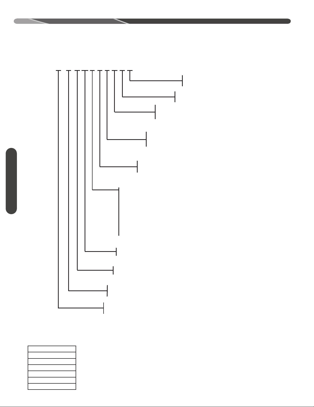
0,125'(6,*16(5,(6
$ ),567'(6,*16(5,(6
Z
7<3(
6,1*/(67$*(
92/7$*(
- 3+
0$-25'(6,*16(5,(6
$ ),567'(6,*16(5,(6
% 6(&21''(6,*16(5,(6
&$3$&,7<
%78+5>N:@
%78+5>N:@
%78+5>N:@
%78+5>N:@
%78+5>N:@
%78+5>N:@
%78+5>N:@
$ D
% )XWXUH/RZ*:3
6((5
$& &21'(16,1*81,7
+3 +($73803
%5$1'
'5 '85$67$5
&21752/6
1121&20081,&$7,1*
'5 $$& $ $ - 1
3.1 Model Number Nomenclature
Specifications
3.2 Available Models
DRAC16A18AJ1NA
DRAC16A24AJ1NA
DRAC16A30AJ1NA
DRAC16A36AJ1NA
DRAC16A42BJ1NA
DRAC16A48AJ1NA
DRAC16A60AJ1NA
6
Page 7
3.0 UNIT SPECIFICATIONS
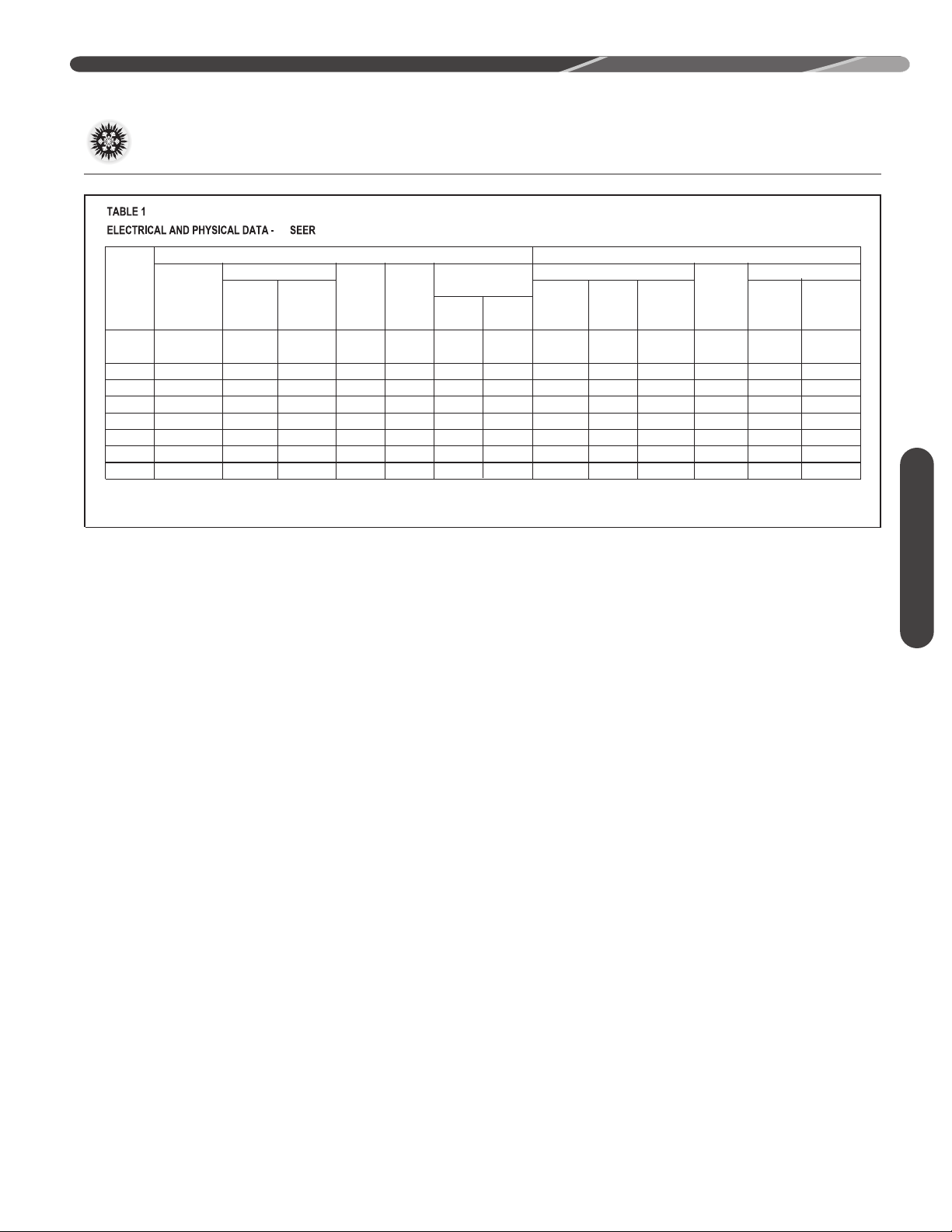
1-60-208/230 9.0/9.0 46 0.5 12/12 15/15 20/20 11.82 [1.10] 1 2049 [967] 81 [2296] 150 [68.0] 157 [71.2]
1-60-208/230 11.2/11.2 60.8 0.36 15/15 20/20 25/25 13.72 [1.27] 1 2077 [980] 85 [2410] 164 [74.4] 171 [77.6]
1-60-208/230 12.8/12.8 64 0.68 17/17 20/20 25/25 16.39 [1.52] 1 2915 [1376] 112 [3175] 168 [76.2] 175 [79.4]
1-60-208/230 15.4/15.4 83.9 1.0 21/21 25/25 35/35 21.85 [2.03] 1 3431 [1619] 128 [3629] 194 [88.0] 201 [91.2]
1-60-208/230 16.7/16.7 109 1.3 23/23 30/30 35/35 18.30 [1.70] 1 3174 [1498] 135 [3827] 176 [79.8] 184 [83.5]
Minimum
Amperes
Maximum
Amperes
Fan Motor
Full Load
Amperes
(FLA)
Minimum
Circuit
Ampacity
Amperes
NOT ES: Factory Refrigerant Charge includes refrigerant for 15 ft. [4.6 m] of standard line set.
Model
Number
ELECTRICAL DATA
Refrig. Per
Circuit
Oz. [g]
Weight
Rated Load
Amperes
(RLA)
Locked
Rotor
Amperes
Face Area
Sq. Ft. [m
2
]
No. Rows CFM [L/s]
Net
Lbs. [kg]
Shipping
Lbs. [kg]
Fuse or HACR
Circuit Breaker
PHYSICAL DATA
Phase
Frequency (Hz)
Voltage (Volts)
Compressor
Outdoor Coil
16
1-60-208/230 18.6/18.6 109 1 25/25 30/30 40/40 21.85 [2.03] 1 3600 [1699] 164 [4649] 194 [88.0] 201 [91.2]
1-60-208/230 21.8/21.8 117 1.7 29/29 35/35 50/50 21.85 [2.03] 2 3615 [1706] 207 [5868] 262 [118.8] 269 [122.0]
1-60-208/230 26.4/26.4 134 1.7 35/35 45/45 60/60 21.85 [2.03] 2 3615 [1706] 228 [6464] 267 [121.1] 274 [124.3]
[-]16A18AJ
[-]16A24AJ
[-]16A30AJ
[-]16A36AJ
[-]16A42AJ
[-]16A42BJ
[-]16A48AJ
[-]16A60AJ
3.3 Electrical and Physical Data
Specifications
7
Page 8
3.0 UNIT SPECIFICATIONS
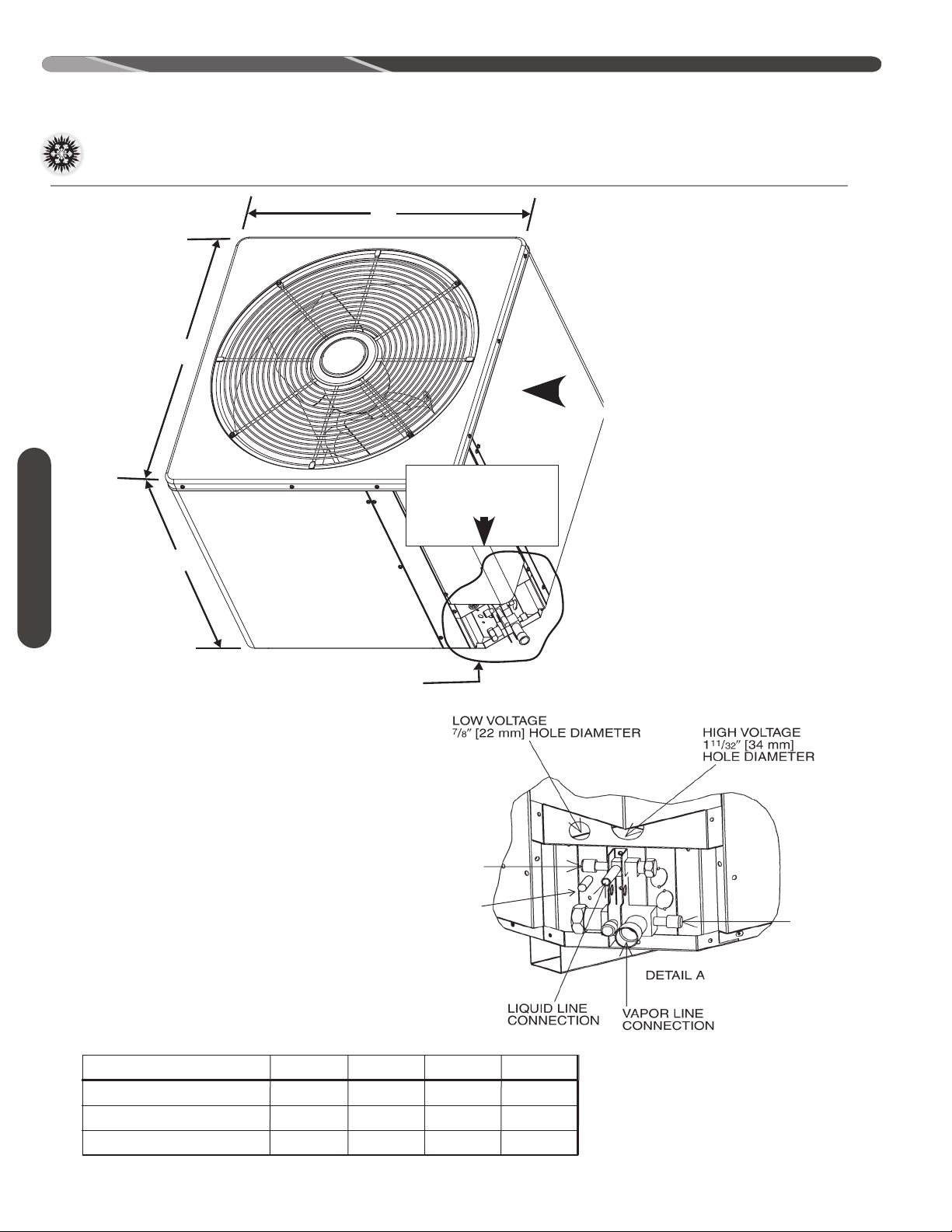
SEE DETAIL A
w
LIQUID
SERVICE
FITTING
TRUE
SUCTION
SERVICE
PORT
VAPOR
SERVICE
FITTING
3.3 Electrical and Physical Data (cont.)
FIGURE 1
DIMENSIONS
Specifications
AIR DISCHARGE: ALLOW
A-00008
60” [152.4 CM] MINIMUM
CLEARANCE.
L
AIR INLETS
(LOUVERED PANELS) ALLOW 6”
[15.2 CM] MINIMUM CLEARANCE
SERVICE ACCESS
ALLOW 24” [61.0 cm]
CLEARANCE
H
NOTE: GRILLE APPEARANCE
MAY VA RY.
8
DIMENSIONAL DATA
16 SEER
Height “H” (in.) [cm]
Length “L” (in.) [cm]
Width “W” (in.) [cm]
*NOTE: “H” dimension includes basepan.
18, 24
241⁄4 [61.6]
275⁄8 [70.2]
275⁄8 [70.2]
42A
321⁄4 [81.9]
275⁄8 [70.2]
275⁄8 [70.2]
30
273/8 [69.5]
315⁄8 [80.3]
315⁄8 [80.3]
36,42B,48,60
353/8 [89.9]
315⁄8 [80.3]
315⁄8 [80.3]
Page 9
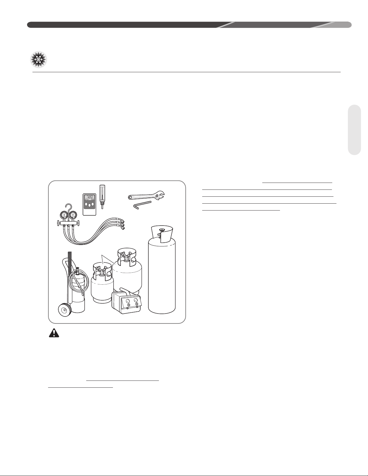
4.1 Tools and Refrigerant
Ambient and Tube
Thermometers
Manifold
Gauge
Set
Brazing
Rods
Torch Nitrogen
Reclaimer
Recovery
Cylinders
Allen Wrench
Crescent Wrench
4.0 INSTALLATION
4.1.1 Tools Required for
Installing and Servicing
R-410A Models
Manifold Sets:
– Up to 800 PSIG [5,516 kPa] High-Side
– Up to 250 PSIG [1,724 kPa] Low-Side
– 550 PSIG [3,792 kPa] Low-Side Retard
Manifold Hoses:
– Service Pressure Rating of 800 PSIG [5,516 kPa]
Recovery Cylinders:
– 400 PSIG [2,758 kPa] Pressure Rating
– Dept. of Transportation 4BA400 or BW400
CAUTION: R-410A systems operate
at higher pressures than R-22 systems. Do not
use R-22 service equipment or components on
R-410A equipment.
4.1.2 Specifications of R-410A
Application: R-410A is not a drop-in
replacement for R-22. Equipment designs must
accommodate its higher pressures. It cannot be
retrofitted into R-22 heat pumps.
Physical Properties: R-410A has an atmospheric
boiling point of -62.9°F [-52.7°C] and its saturation
pressure at 77°F [25°C] is 224.5 psig [1,548 kPa].
Composition: R-410A is a near-azeotropic
mixture of 50% by weight difluoromethane
(HFC-32) and 50% by weight pentafluoroethane
(HFC-125).
Pressure: The pressure of R-410A is
approximately 60% (1.6 times) greater than
R-22. Recovery and recycle equipment, pumps,
hoses, and the like must have design pressure
ratings appropriate for R-410A. Manifold sets need
to range up to 800 psig [5,516 kPa] high-side and
250 psig [1,724 kPa] low-side with a 550 psig
[3,792 kPa] low-side retard. Hoses need to have
a service pressure rating of 800 psig [5,516 kPa].
Recovery cylinders need to have a 400 psig [2,758
kPa] service pressure rating, DOT 4BA400 or DOT
BW400.
Combustibility: At pressures above 1
atmosphere, a mixture of R-410A and air can
become combustible. R-410A and air should
never be mixed in tanks or supply lines or
be allowed to accumulate in storage tanks.
Leak checking should never be done with a
mixture of R-410A and air. Leak-checking can
be performed safely with nitrogen or a mixture of
R-410A and nitrogen.
4.1.3 Quick-Reference Guide
for R-410A
• R-410A refrigerant operates at approximately
60% higher pressure (1.6 times) than R-22.
Ensure that servicing equipment is designed to
operate with R-410A.
• R-410A refrigerant cylinders are light rose in
color.
• R-410A, as with other HFCs, is only compatible
with POE oils.
• Vacuum pumps will not remove moisture from
POE oil used in R-410A systems.
• R-410A systems are to be charged with liquid
refrigerants. Prior to March 1999, R-410A
refrigerant cylinders had a dip tube. These
cylinders should be kept upright for equipment
charging. Post-March 1999 cylinders do not
have a dip tube and should be inverted to ensure
liquid charging of the equipment.
• Do not install a suction line filter drier in the liquid line.
• A factory-approved liquid line filter drier is
shipped with every unit and must be installed
in the liquid line at the time of installation. Only
manufacturer-approved liquid line filter driers
should be used. FIlter driers must be rated for
a working pressure of at least 600 psig [4,137
kPa]. The filter drier will only have adequate
moisture-holding capacity if the system is
properly evacuated.
• Desiccant (drying agent) must be compatible for
POE oils and R-410A refrigerant.
Tools
9
Page 10
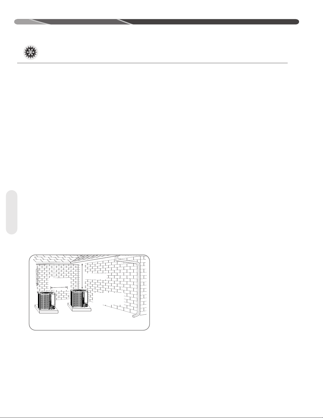
12” Min. (30.5 cm) 24”
[61.0 CM]
RECOMMENDED
SERVICE PANELS/
INLET CONNECTIONS
/ HIGH & LOW
VOLTAGE ACCESS
ALLOW 24” [ 61.0 cm] OF
CLEARANCE
ALLOW 60” [152.4 cm]
OF CLEARANCE
AIR INLET LOUVERS ALLOW
6” [15.2 cm] Min. OF
CLEARANCE ALL SIDES
12” [30.5 cm] RECOMMENDED
ST-A1226-177-00
4.0 INSTALLATION
4.2 Choosing a Location
4.2.1 Allowable Clearances
12" [30.5 cm] to side intake louvers
24" [61.0 cm] to service access panels
60" [152.4 cm] vertical for fan discharge
If space limitations exist, the following clearances
will have minimal impact to capacity and efficiency
and are permitted:
Single-Unit Applications: Minimum of 6" [15.2
cm] to side intake louvers. Do not reduce the 60"
[152.4 cm] for fan discharge or the 24" [61.0 cm]
service clearances.
Multiple-Unit Applications: For units positioned
next to each other, a minimum of 6" [15.2 cm]
clearance between units is recommended for 1.5
and 2 ton models and 9" [22.9 cm] for 2.5 ton to
5 ton models. Do not reduce the 60" [152.4 cm]
for fan discharge or the 24" [61.0 cm] service
clearances.
IMPORTANT: Consult local and
national building codes and ordinances for special
installation requirements. Following location
information will provide longer life and simplified
servicing of the outdoor unit.
Location
NOTICE: These units must be installed
outdoors. No ductwork can be attached, or
other modifications made, to the discharge grille.
Modifications will affect performance or operation.
4.2.2 Operational Issues
Related to Unit Location
IMPORTANT: Locate the unit
in a manner that will not prevent, impair, or
compromise the performance of other equipment
installed in proximity to the unit. Maintain all
required minimum distances to gas and electric
meters, dryer vents, and exhaust and inlet
openings. In the absence of national codes or
manufacturers’ recommendations, local code
recommendations and requirements will take
precedence.
• Refrigerant piping and wiring should be properly
sized and kept as short as possible to avoid
capacity losses and increased operating costs.
• Locate the unit where water runoff will not create
a problem with the equipment. Position the unit
away from the drip edge of the roof whenever
possible. Units are weatherized, but can be
affected by the following:
• Water pouring into the unit from the junction
of rooflines, without protective guttering. Large
volumes of water entering the unit while in
operation can impact fan blade or motor life.
• Closely follow the clearance recommendations in
section 4.2.1.
• 24" [61.0 cm] to the service panel access
• 60" [152.4 cm] above fan discharge (unit top)
to prevent recirculation
• 6" [15.2 cm] to coil grille air inlets
with 12" [30.5 cm] minimum recommended
10
Page 11
4.2 Choosing a Location (cont.)
4.0 INSTALLATION
4.2.3 Corrosive Environment
The metal parts of this unit may be subject to rust or
deterioration if exposed to a corrosive environment.
This oxidation could shorten the equipment’s useful
life.
Corrosive elements include, but are not limited to,
salt spray, fog or mist in seacoast areas, sulphur or
chlorine from lawn watering systems, and various
chemical contaminants from industries such as paper
mills and petroleum refineries.
If the unit is to be installed in an area where
contaminants are likely to be a problem, special
attention should be given to the equipment location
and exposure.
• Avoid having lawn sprinkler heads spray directly on
the unit cabinet.
• In coastal areas, locate the unit on the side of the
building away from the waterfront.
• Shielding provided by a fence or shrubs may give
some protection, but cannot violate minimum
airflow and service access clearances.
WARNING: Disconnect all power to
unit before starting maintenance. Failure to do so can
cause electrical shock resulting in severe personal
injury or death.
Regular maintenance will reduce the buildup of
contaminants and help to protect the unit’s finish.
• Frequent washing of the cabinet, fan blade, and
coil with fresh water will remove most of the salt or
other contaminants that build up on the unit.
• A good liquid cleaner may be used several times
a year to remove matter that will not wash off with
water.
4.2.4 Customer Satisfaction
Issues
• The outdoor unit should be located away from the
living, sleeping, and recreational spaces of the
owner and those spaces on adjoining property.
• To prevent noise transmission, the mounting pad
for the outdoor unit should not be connected to
the structure and should be located a sufficient
distance above grade to prevent ground water from
entering the unit.
Location Mounting
4.3 Mounting Unit
4.3.1 Unit Mounting Methods
The outdoor unit may be mounted in a number of
ways. The most common method is on a ground
mounted concrete or pre-fabricated pad. It can also
be mounted on a ground or roof mounted metal frame,
wooden frame, or 4” x 4” [10.2 cm x 10.2 cm] wooden
stringers. It is extremely important to properly secure
the unit to the pad or frame so it does not shift during
high winds, seismic events, or other outside forces to
eliminate the possibility of a safety hazard or physical
damage to the unit. Local codes in regions subject
to frequent hurricanes and seismic events will dictate
specific mounting requirements and must be followed.
4.3.2 High Wind and Seismic
Tie-Down Methods
The manufacturer-approved/recommended method is
a guide to securing equipment for wind and seismic
loads. Other methods might provide the same result,
but the manufacturer method is the only one endorsed
by the manufacturer for securing equipment where
wind or earthquake damage can occur. Additional
information is available on the manufacturer's website
or from the wholesale distributor.
11
Page 12
4.0 INSTALLATION
ST-A1226-178-00
BASE PAD
(CONCRETE OR OTHER
SUITABLE MATERIAL)
DO NOT BLOCK
OPENINGS
IN BASE PAN
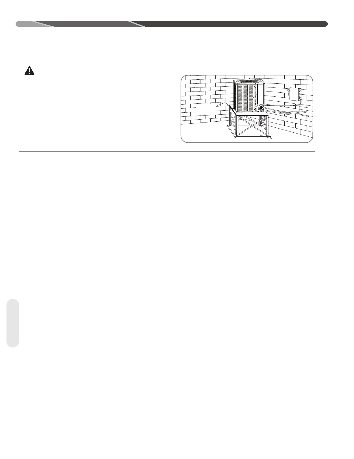
4.3.3 Elevating Unit
WARNING:
elevating stand in order to prevent tipping. Failure to do so may
result in severe personal injury or death.
If elevating the unit, either on a flat roof or on a slab, observe the
following guidelines.
• If elevating a unit on a flat roof, use 4" x 4" [10.2 cm x 10.2 cm] or
equivalent stringers positioned to distribute unit weight evenly and
prevent noise and vibration.
Secure an elevated unit and its
NOTICE: Do not block drain openings on bottom of
unit.
Mounting
12
Page 13

4.4 Refrigerant Line Set Selection
4.4.1 Replacing Existing Systems
To prevent failure of a new unit, the existing line set
must be correctly sized for the new unit and must
be cleaned or replaced. Care must be taken so
the expansion device is not plugged. For new and
replacement units, a liquid line filter drier must be
installed and the line set must be properly sized.
Test the oil for acid. If it tests positive for acid, a
suction line filter drier is mandatory.
4.4.2 Line Set Length and Fitting Losses
IMPORTANT: When replacing an
R-22 unit with an R-410A unit, either replace
the line set or ensure that residual mineral oil is
drained from existing lines including oil trapped in
low spots.
4.0 INSTALLATION
Refrigerant tubing is measured in terms of actual
length and equivalent length. Actual length is used
for refrigerant charge applications. Equivalent
length takes into account pressure losses from
Table 1
ƋƵŝǀĂůĞŶƚ>ĞŶŐƚŚĨŽƌ&ŝƚƚŝŶŐƐ;ĨƚͿŵ
ϵϬΣ^ŚŽƌƚ
>ŝŶĞ^ŝnjĞ
;ŝŶͿŵŵ
ϯϴϵϱϯ ϭϯϬϰϬ ϬϴϬϮϰ ϬϯϬϬϵ ϲϭϴϯ ϰϭϮϮ ϬϰϬϭϮ ϲϭϴϯ
ϭϮϭϮϳϭ ϭϰϬϰϯ ϬϵϬϮϳ ϬϰϬϭϮ ϵϮϳϰ ϱϭϱϮ ϬϲϬϭϴ ϲϭϴϯ
ϱϴϭϱϴϴ ϭϱϬϰϲ ϭϬϯϬ ϬϱϬϭϱ ϭϮϯϲϲ ϲϭϴϯ ϬϴϬϮϰ ϲϭϴϯ
ϯϰϭϵϬϱ ϭϵϬϱϴ ϭϯϬϰϬ ϬϲϬϭϴ ϭϰϰϮϳ ϳϮϭϯ ϬϵϬϮϳ ϲϭϴϯ
ϳϴϮϮϮϯ ϮϯϬϳϬ ϭϱϬϰϲ ϬϳϬϮϭ ϭϱϰϱϳ ϴϮϰϰ ϭϬϯϬ ϲϭϴϯ
ϭͲϭϴϮϴϱϴ ϮϳϬϴϮ ϭϴϬϱϱ ϬϵϬϮϳ ϮϮϲϳϭ ϭϮϯϲϲ ϭϱϬϰϲ ϲϭϴϯ
ZĂĚŝƵƐ
ůďŽǁ
ϵϬΣ>ŽŶŐ
ZĂĚŝƵƐ
ůďŽǁ
ϰϱΣ
ůďŽǁ
tubing length, ttings, vertical separation, accessories, and lter driers. The table below references
commonly used equivalent lengths.
^ŽůĞŶŽŝĚ
sĂůǀĞ
ŚĞĐŬ
sĂůǀĞ
^ŝƚĞ
'ůĂƐƐ
&ŝůƚĞƌ
ƌŝĞƌ
4.4.3 Liquid Line Selection
The purpose of the liquid line is to transport warm
sub-cooled liquid refrigerant between the outdoor
unit to the indoor unit. It is important not to allow
the refrigerant to ash into superheated vapor prior
to the expansion device of the indoor coil. The
ashing of refrigerant can occur for the following
reasons:
• Low refrigerant charge
• Improperly selected liquid line size
• Absorption of heat prior to expansion device
• Excessive vertical separation between the out-
door unit and indoor coil
• Restricted liquid line or lter drier
• Kinked liquid line
The total pressure drop allowed for the liquid line is
50 PSI [345 kPa]. The procedure for selecting the
proper liquid line is as follows:
• Measure the total amount of vertical separation
between the outdoor unit and indoor coil.
• Measure the linear length of liquid line needed.
• Add all of the equivalent lengths associated with
any ttings or accessories using Table 1 above.
• Add the linear length to the total tting equivalent length. This will equal your total equivalent
line length.
• Reference Table 2 to verify the calculated
equivalent length is acceptable with the required
vertical separation and diameter of liquid line.
Tubing
13
Page 14
4.0 INSTALLATION
1/4" 5/8" n/a 25 / 1.00 50 / 0.99 62 / 0.98 43 / 0.98 24 / 0.97 5 / 0.97
NR NR NR NR
1/4" 3/4" ** n/a 25 / 1.00 50 / 1.00 62 / 0.99 43 / 0. 99 24 / 0.99 5 / 0.99 NR NR NR NR
1/4" 5/8" n/a 25 / 0.99 50 / 0.98 21 / 0.97 N R NR NR NR NR NR NR
1/4" 3/4" n/a 25 /1.00 50 / 1.00 21 / 0.99 N R NR NR NR NR NR NR
6) Applicaons s haded in dark gray are not recommended due to excessive liquid or sucon pressure drop.
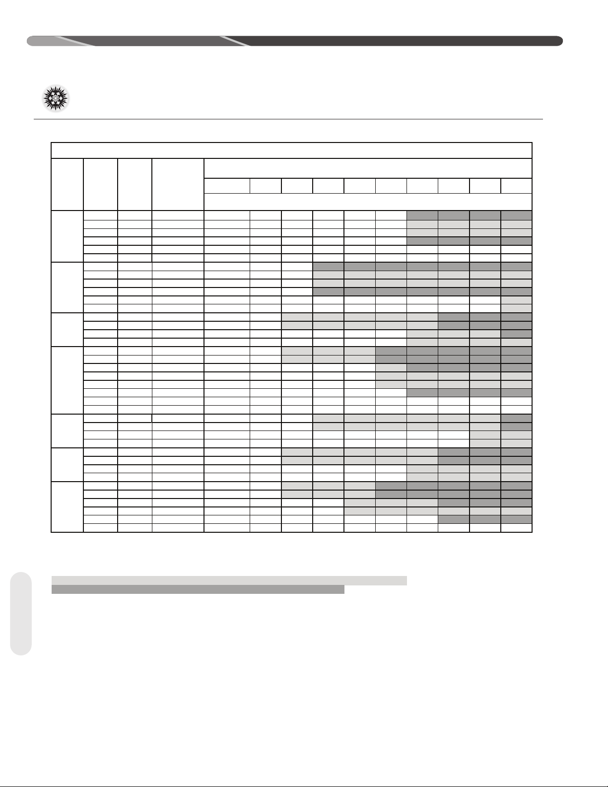
16 SEER Single-Stage Air-Condioners
4.4 Refrigerant Line Set Selection (cont.)
Table 2A: Refrigerant Line Sizing Chart (English Units)
Apply Long Line
Unit Size
Notes:
1) Do not exceed 200 linear line l ength.
2) * Do not exceed 180 vercal separaon if outdoor unit is above indoor unit.
3) ** 3/4" suc on line should only be used for 1.5 ton systems if outdoor unit is below or at same level as indoor to assure proper oil return.
4) Always use
5) Applicaons s haded in light gray indicate capacity mulpliers between 0.90 and 0.96 which are not recommended, but are allowed.
Allowable
Liquid Line
1.5 Ton
** SEE
NOTE 3
2 Ton
2.5 Ton
3 Ton
3.5 Ton
4 Ton
5 Ton
the smallest liquid line all owable to minimize refrigerant charge.
Allowable
Sucon Line
Size
5/16" 5/8" 190 25 / 1.00 50 / 0.99 75 / 0.98 98 / 0.98 93 / 0.97 88 / 0.97 83 / 0.96 78 / 0.96 73 / 0.95 68 / 0.94
3/8" 5/8" 127 25 / 1.00 50 / 0.99 75 / 0. 98 100 / 0.98 100 / 0.97 100 / 0.97 100 / 0. 96 100 / 0.96 100 / 0.95 100 / 0.94
5/16" 3/4" ** 190 25 / 1.00 50 / 1.00 75 / 0.99 98 / 0.99 93 / 0.99 88 / 0.99 83 / 0.99 78 / 0.98 73 / 0.98 68 / 0.98
3/8" 3/4" ** 127 25 / 1.00 50 / 1.00 75 / 1.00 100 / 0.99 100 / 0.99 100 / 0.99 100 / 0.99 100 / 0.98 100 / 0.98 100 / 0.98
5/16" 5/8" 180 25 / 0.99 50 / 0.98 75 / 0.97 87 / 0.96 77 / 0.95 69 / 0.94 61 / 0.93 53 / 0.92 45 / 0.91 37 / 0.90
3/8" 5/8" 120 25 / 0.99 50 / 0.98 75 / 0. 97 100 / 0.96 100 / 0.95 100 / 0.94 98 / 0.93 95 / 0.92 92 / 0.91 89 / 0.90
5/16" 3/4" 180 25 /1.00 50 / 1.00 75 / 0.99 87 / 0.99 77 / 0.98 69 / 0.98 61 / 0.98 53 / 0.97 45 / 0.97 37 / 0.96
3/8" 3/4" 120 25 / 1.00 50 / 1.00 75 / 0. 99 100 / 0.99 100 / 0.98 100 / 0.98 98 / 0.98 95 / 0.97 93 / 0.97 90 / 0.96
5/16" 5/8" 113 25 / 0.99 50 / 0.98 75 / 0.96 70 / 0.94 59 / 0.93 48 / 0.91 36 / 0.90 NR NR NR
3/8" 5/8" 75 25 / 0.99 50 / 0.98 75 / 0.96 100 / 0.94 98 / 0.93 94 / 0.91 90 / 0.90 NR NR NR
5/16" 3/4" 113 25 / 1.00 50 / 0.99 75 /
3/8" 3/4" 75 25 / 1.00 50 / 0.99 75 / 0.99 100 / 0.98 98 / 0.98 94 / 0.97 90 / 0.96 86 / 0.96 82 / 0.95 78 / 0.95
5/16" 5/8" 73 25 / 0.99 50 / 0.97 66 / 0.94 49 / 0.92 32 / 0.90 NR NR NR NR NR
3/8" 5/8" 48 25 / 0.99 50 / 0.97 75 / 0.94 95 / 0. 92 89 / 0.90 NR NR NR NR NR
5/16" 3/4" 73 25 / 1.00 50 / 0.99 66 / 0.98 49 / 0.98 32 / 0.97 15 / 0.96 NR NR NR NR
3/8" 3/4" 48 25 / 1.00 50 / 0.99 75 / 0
1/2" 3/4" 24 25 / 1.00 50 / 0.99 75 / 0.98 100 / 0.98 100 / 0.97 100 / 0.96 100 / 0.95 100 / 0.94 100 / 0.93 100 / 0.93
5/16" 7/8" 73 25 / 1.00 50 / 1.00 66 / 1.00 49 / 0.99 32 / 0.99 15 / 0.99 NR NR NR NR
3/8" 7/8" 48 25 / 1.00 50 / 1.00 75 / 1.00 95 / 0. 99 89 / 0.99 84 / 0.99 78 / 0.98 72 / 0.98 67 / 0.98 61 / 0.97
1/2" 7/8" 24 25 / 1.00 50 / 1.00 75 / 1.00 100 / 0.99 100 / 0
3/8" 3/4" 100 25 / 0.99 50 / 0.98 75 / 0. 97 88 / 0.96 80 / 0.95 72 / 0.94 65 / 0.92 57 / 0.91 49 / 0.90 NR
1/2" 3/4" 50 25 / 0.99 50 / 0.98 75 / 0.97 100 / 0.96 100 / 0.95 100 / 0.94 100 / 0.92 100 / 0.91 100 / 0.90 NR
3/8" 7/8" 100 25 / 1.00 50 / 1.00 75 / 0. 99 88 / 0.99 80 / 0.99 72 / 0.98 65 / 0.97 57 / 0.97 49 / 0.96 42 / 0.96
1/2" 7/8" 50 25 / 1.00 50 / 1.00 75 / 0.99 100 / 0.99 100 /
3/8" 3/4" 0 25 / 0.99 50 / 0.98 75 / 0.96 77 / 0.95 67 / 0.93 57 / 0.92 46 / 0.91 NR NR NR
1/2" 3/4" 0 25 / 0.99 50 / 0.98 75 / 0.96 100 / 0.95 100 / 0. 93 100 / 0.92 100 / 0.91 NR NR NR
3/8" 7/8" 0 25 / 1.00 50 / 0.99 75 / 0.99 77 / 0.98 67 / 0.97 57 / 0.97 46 / 0.96 36 / 0.96 26 / 0.95 15 / 0.95
1/2" 7/8" 0 25 / 1.00 50 / 0.99 75 / 0.99 100 / 0.98 100 / 0. 97 100 / 0.97 100 / 0.96 100 / 0.96 9
3/8" 3/4" 0 25 / 0.99 50 / 0.97 75 / 0.94 61 / 0.92 46 / 0.90 NR NR NR NR N R
1/2" 3/4" 0 25 / 0.99 50 / 0.97 75 / 0.94 100 / 0.92 100 / 0. 90 NR NR NR NR NR
3/8" 7/8" 0 25 / 1.00 50 / 0.99 75 / 0.98 61 / 0.97 46 / 0.96 32 / 0.95 18 / 0.94 NR NR NR
1/2" 7/8" 0 25 / 1.00 50 / 0.99 75 / 0.98 100 / 0.97 100 /0.96 100 / 0. 95 97 / 0.94 95 / 0.94 92 / 0.93 89 / 0.92
3/8" 1-1/8" 0 25 / 1.01 50 / 1.01 75 / 1.00 61 / 1.00 46 / 0.99 32 / 0.99 18 / 0.
1/2" 1-1/8" 0 25 / 1.01 50 / 1.01 75 / 1.00 100 /1.00 100 / 0.99 100 / 0.99 97 / 0.99 95 / 0.99 92 / 0.99 89 / 0.98
Size
Guideli nes if
Linear Line Length
Exceeds Those
Shown Below
(Feet)
< 25 26-50 51-75 76- 100 101-125 126-150 151-175 176-200 201-225 226-250
Maximum Vercal Rise (Outdoor Unit Below Indoor Unit) * / Capacity Mulplier
0.99 70 / 0.98 59 / 0.98 48 / 0.97 36 / 0.96 25 / 0.96 13 / 0.95 NR
.98 95 / 0.98 89 / 0.97 84 / 0.96 78 / 0.95 72 / 0.94 67 / 0.93 61 / 0.93
Equivalent Length (Feet)
.99 100 / 0.99 100 / 0.98 100 / 0.98 100 / 0.98 100 / 0.97
0.99 100 / 0.98 100 / 0.97 100 / 0.97 100 / 0.96 100 / 0.96
9 / 0.95 97 / 0.95
99 NR NR NR
Tubing
14
Page 15

4.0 INSTALLATION
6.35 [1/4] 15.88 [5/8] n/a 8 / 1.00 15 / 0.99 19 / 0.98 13 / 0.98 7 / 0.97 2 / 0.97 NR NR NR NR
6.35 [1/4] 19.05 [3/4] ** n/a 8 / 1.00 15 / 1.00 19 / 0.99 13 / 0.99 7 / 0.99 2 / 0.99 NR N R NR NR
6.35 [1/4] 15.88 [5/8] n/a 8 / 0.99 15 / 0.98 6 / 0.97 NR NR NR NR NR N R NR
6.35 [1/4] 19.05 [3/4] n/ a 8 / 1.00 15 / 1.00 6 / 0.99 N R NR NR NR NR NR NR
6) Applicaons s haded in dark gray are not recommended due to excessi ve liquid or sucon pressure drop.
16 SEER Single-Stage Air-Condioners
< 25 26- 50 51-75 76- 100 101-125 126- 150 151-175 176-200 201- 225226-250
5/16"5/8"7325 / 0.99 50 / 0.97 66 / 0.94 49 / 0.92 32 / 0.90 NR NR NR NR NR
3/8" 5/8" 48 25 / 0.99 50 / 0.97 75 / 0.94 95 / 0.92 89 / 0.90 NR NR NR NR NR
5/16"3/4"7325 / 1.00 50 / 0.99 66 / 0.98 49 / 0.98 32 / 0.97 15 / 0.96 NR NR NR NR
3/8" 3/4" 48 25 / 1.00 50 / 0.99 75 / 0.98 95 / 0.98 89 / 0.97 84 / 0.96 78 / 0.95 72 / 0.94 67 / 0.93 61 / 0.93
1/2" 3/4" 24 25 / 1.00 50 / 0.99 75 / 0.98 100 / 0.98 100 / 0.97 100 / 0.96 100 / 0.95 100 / 0.94 100 / 0.93 100 / 0.93
5/16"7/8"7325 / 1.00 50 / 1.00 66 / 1.00 49 / 0.99 32 / 0.99 15 / 0.99 NR NR NR NR
3/8" 7/8" 48 25 / 1.00 50 / 1.00 75 / 1.00 95 / 0.99 89 / 0.99 84 / 0.99 78 / 0.98 72 / 0.98 67 / 0.98 61 / 0.97
1/2" 7/8" 24 25 / 1.00 50 / 1.00 75 / 1.00 100 / 0.99 100 / 0.99 100 / 0.99 100 / 0.98 100 / 0.98 100 / 0.98 100 / 0.97
Excerp t from Table 3A
Apply Long Line
Guidelines if
Linear Line Length
Exceeds Those
Shown Below
(Feet)
Equivelent Length (Feet)
Maximum Vercal Rise (Outdoor Unit Below Indoor Unit) * / Capaci ty Mulplier
3 Ton
Unit Size
Allowable
Liquid Line
Size
Allowable
Sucon Line
Size
4.5 Refrigerant Line Set Selection (cont.)
Table 2B: Refrigerant Line Sizing Chart (Metric Units)
Apply Long Line
Allowable
Liquid Line
Unit Size
5.3 KW
7.94 [5/16] 15.88 [5/8] 58 8 / 1.00 15 / 0.99 23 / 0.98 30 / 0.98 28 / 0.97 27 / 0.97 25 / 0.96 24 / 0. 96 22 / 0.95 21 / 0.94
[1.5 Ton]
** SEE
7.94 [5/16] 19.05 [3/4] ** 58 8 / 1.00 15 / 1.00 23 / 0.99 30 / 0. 99 28 / 0.99 27 / 0.99 25 / 0.99 24 / 0.98 22 / 0. 98 21 / 0.98
NOTE 3
7.94 [5/16] 15.88 [5/8] 55 8 / 0.99 15 / 0.98 23 / 0.97 27 / 0.96 23 / 0.95 21 / 0.94 19 / 0.93 16 / 0. 92 14 / 0.91 11 / 0.90
7.0 KW
[2 Ton]
7.94 [5/16] 19.05 [3/4] 55 8 / 1.00 15 / 1.00 23 / 0.99 27 / 0.99 23 / 0.98 21 / 0.98 19 / 0.98 16 / 0. 97 14 / 0.97 11 / 0.96
7.94 [5/16] 15.88 [5/8] 34 8 / 0.99 15 / 0.98 23 / 0.96 21 / 0.94 18 / 0.93 15 / 0.91 11 / 0.90 NR NR NR
8.8 KW
[2.5 Ton]
7.94 [5/16] 19.05 [3/4] 34 8 / 1.00 15 / 0.99 23 / 0.99 21 / 0.98 18 / 0.98 15 / 0.97 11 / 0.96 8 / 0.96 4 / 0.95 NR
7.94 [5/16] 15.88 [5/8] 22 8 / 0.99 15 / 0.97 20 / 0.94 15 / 0.92 10 / 0.90 NR NR NR NR NR
7.94 [5/16] 19.05 [3/4
10.6 KW
[3 Ton]
7.94 [5/16] 22.23 [7/8] 22 8 / 1.00 15 / 1.00 20 / 1.00 15 / 0.99 10 / 0.99 5 / 0.99 NR NR NR NR
12.3 KW
[3.5 Ton]
14.1 KW
[4 Ton]
17.6 KW
[5 Ton]
Notes:
1) Do not
exceed 61 meters linear line length.
2) * Do not exceed 55 meters vercal s eparaon if outdoor unit is above indoor unit.
3) ** 19.05 mm [3/4 in.] vapor line should only be used for 1.5 ton systems if outdoor unit is below or at same level as indoor unit to assure proper oil return.
4) Always us e the smalles t liquid line allowable to minimize refri gerant charge.
5) Applicaons s haded in light gray
Allowable
Sucon Line
Size
mm [in.]
9.53 [3/8] 15.88 [5/8] 39 8 / 1.00 15 / 0.99 23 / 0.98 30 / 0.98 30 / 0.97 30 / 0.97 30 / 0.96 30 / 0.96 30 / 0. 95 30 / 0.94
9.53 [3/8] 19.05 [3/4] ** 39 8 / 1.00 15 / 1.00 23 / 0.99 30 / 0.99 30 / 0. 99 30 / 0.99 30 / 0.99 30 / 0.98 30 / 0.98 30 / 0.98
9.53 [3/8] 15.88 [5/8] 37 8 / 0.99 15 / 0.98 23 / 0.97 30 / 0.96 30 / 0.95 30 / 0.94 30 / 0.93 29 / 0.92 28 / 0. 91 27 / 0.90
9.53 [3/8] 19.05 [3/4] 37 8 / 1.00 15 / 1.00 23 / 0.99 30 / 0.99 30 / 0.98 30 / 0.98 30 / 0.98 29 / 0.97 28 / 0. 97 27 / 0.96
9.53 [3/8] 15.88 [5/8] 23 8 / 0.99 15 / 0.98 23 / 0.96 30 / 0.94 30 / 0.93 29 / 0.91 27 / 0.
9.53 [3/8] 19.05 [3/4] 23 8 / 1.00 15 / 0.99 23 / 0.99 30 / 0.98 30 / 0.98 29 / 0.97 27 / 0.96 26 / 0.96 25 / 0. 95 24 / 0.95
9.53 [3/8] 15.88 [5/8] 15 8 / 0.99 15 / 0.97 23 / 0.94 29 / 0.92 27 / 0.90 NR N R NR NR NR
9.53 [3/8] 19.05 [3/4] 15 8 / 1.00 15 / 0.99 23 / 0.98 29 / 0.98 27 / 0.97 26 / 0.96 24 / 0.95 22 / 0.94 20 / 0. 93 19 / 0.93
12.7 [1/2] 19.05 [3/4] 7 8 / 1.00 15 / 0.99 23 / 0.98 30 / 0.98 30 / 0. 97 30 / 0.96 30 / 0.95 30 / 0.94 30 / 0.93 30 / 0.93
9.53 [3/8] 22.23 [7/8] 15 8 / 1.0
1/2 [12. 7] 22.23 [7/8] 7 8 / 1.00 15 / 1.00 23 / 1. 00 30 / 0.99 30 / 0.99 30 / 0.99 30 / 0.98 30 / 0.98 30 / 0. 98 30 / 0.97
9.53 [3/8] 19.05 [3/4] 30 8 / 0.99 15 / 0.98 23 / 0.97 27 / 0.96 24 / 0.95 22 / 0.94 20 / 0.92 17 / 0.91 15 / 0. 90 NR
12.7 [1/2] 19.05 [3/4] 15 8 / 0.99 15 / 0.98 23 / 0.97 30 / 0.96 30 / 0.95 30 / 0.94 30 / 0.92 30 / 0.91 30 / 0. 9
9.53 [3/8] 22.23 [7/8] 30 8 / 1.00 15 / 1.00 23 / 0.99 27 / 0.99 24 / 0.99 22 / 0.98 20 / 0.97 17 / 0.97 15 / 0. 96 13 / 0.96
12.7 [1/2] 22.23 [7/8] 15 8 / 1.00 15 / 1.00 23 / 0.99 30 / 0.99 30 / 0.99 30 / 0.98 30 / 0.97 30 / 0.97 30 / 0. 96 30 / 0.96
9.53 [3/8] 19.05 [3/4] 0 8 / 0.99 15 / 0.98 23 / 0.96 24 / 0.95 20 / 0. 93 17 / 0.92 14 / 0.91 N R NR NR
12.7 [1/2] 19.05 [3/4] 0 8 / 0.99 15 / 0.98 23 / 0.96 30 / 0.95 30 / 0. 93 30 / 0.92 30 / 0.9
9.53 [3/8] 22.23 [7/8] 0 8 / 1.00 15 / 0.99 23 / 0.99 24 / 0.98 20 / 0. 97 17 / 0.97 14 / 0.96 11 / 0.96 8 / 0.95 5 / 0.95
12.7 [1/2] 22.23 [7/8] 0 8 / 1.00 15 / 0.99 23 / 0.99 30 / 0.98 30 / 0. 97 30 / 0.97 30 / 0.96 30 / 0.96 30 / 0.95 30 / 0.95
9.53 [3/8] 19.05 [3/4] 0 8 / 0.99 15 / 0.97 23 / 0.94 19 / 0.92 14 / 0. 90 NR NR NR NR NR
12.7 [1/2] 19.05 [3/4] 0 8 / 0.99 15 / 0.97 23 / 0.94 30 / 0.92 30 / 0. 90 NR NR NR NR NR
9.53 [3/8] 22.23 [7/8]
12.7 [1/2] 22.23 [7/8] 0 8 / 1.00 15 / 0.99 23 / 0.98 30 / 0.97 30 /0.96 30 / 0.95 30 / 0. 94 29 / 0.94 28 / 0.93 27 / 0.92
9.53 [3/8] 28.58 [1-1/8] 0 8 / 1.01 15 / 1.01 23 / 1.00 19 / 1.00 14 / 0.99 10 / 0.99 5 / 0.99 NR N R NR
12.7 [1/2] 28.58 [1-1/8] 0 8 / 1.01 15 / 1.01 23 / 1.00 30 / 1.00 30 / 0.99 30 / 0.99 30 / 0. 99 29 / 0.99 28 / 0.99 27 / 0.98
mm [in.]
Guideline s if
Linear Line
Length Exceeds
Size
Those Shown
Below
(Meters)
] 22 8 / 1.00 15 / 0.99 20 / 0.98 15 / 0. 98 10 / 0.97 5 / 0.96 NR NR NR NR
0 8 / 1.00 15 / 0.99 23 / 0.98 19 / 0.97 14 / 0.96 10 / 0.95 5 / 0.94 NR NR NR
indicate capacity mulpliers between 0.90 and 0.96 which are not recommended, but are allowed.
< 8 8-15 16-23 24-30 31-38 39-46 47-53 54-61 62-69 70-76
Maximum Vercal Rise (Outdoor Unit Below Indoor Unit) * / Capacity Mulplier
0 15 / 1.00 23 / 1.00 29 / 0.99 27 / 0.99 26 / 0.99 24 / 0.98 22 / 0.98 20 / 0.98 19 / 0. 97
Equivalent Length (Meters)
90 NR NR NR
1 NR NR NR
0 NR
Example: A 3 ton system is installed 50' below
the indoor unit, requires a 75' of 1/2" diameter
liquid line, 3/4" diameter suction line, and 4 90° LR
elbows, and a lter drier.
• Fitting Equivalent Length (ft.) = (4 × .9') + 6' = 9.6'
• Total Equivalent Length (ft.) = 75' + 9.6' = 84.6'
This application is acceptable because the 50' vertical rise is less than the maximum rise of 100' for
this application. The application is also considered
to have a long line set since 75 linear feet exceeds
the limit of 24 feet. Reference the long line set sec-
tion of the I&O for detail.
Tubing
15
Page 16

4.0 INSTALLATION
4.4 Refrigerant Line Set Selection (cont.)
4.4.4 Suction Line Selection
Purpose of the suction line is to return superheated
vapor to the condensing unit from the evaporator.
Proper suction line sizing is important because
it plays an important role in returning oil to the
compressor to prevent potential damage to the
bearings, valves, and scroll sets. Also, an undersized suction line can dramatically reduce capacity
and performance of the system. The procedure for
selecting the proper suction line is as follows:
• Determinate the total linear length of suction line
required.
• Add all of the equivalent lengths associated with
any ttings or accessories using the table on
previous page.
• Add the linear length and total tting equivalent length. This will equal your total equivalent
length.
• Reference Table 2 to verify that the calculated
equivalent length falls within the acceptable
region of the chart.
• Verify the capacity dierence is compatible with
the application using the multiplier in Table 2.
• Use only suction line sizes listed in Table 2.
4.4.5 Long Line Set
Considerations
Long line set applications are dened as applications that require accessories or alternate construction methods. The following things must be
considered when selecting and installing a long line
set:
• Additional refrigerant charge
• Fitting losses and maximum equivalent length
considerations
• Refrigerant migration during the o cycle
• Oil return to the compressor
• Capacity losses
• System oil level adjustment
4.4.5.1 Determining if Long Line
Set Length Requirements Apply
Table 2 is used to determine if the application is
considered to have a long line set. A column is provided that shows the linear line length where long
Tubing
line length requirements apply.
4.4.5.2 Oil Return to Compressor
Small amounts of compressor crankcase oil is
picked up and carried out of the compressor by
the moving refrigerant and is circulated through the
system along with the refrigerant before it returns
to the compressor crankcase. It is critical to the life
of the compressor for the oil to be able to return to
the compressor to maintain an adequate level of
oil in the compressor crankcase. Oversized vapor
lines result in inadequate refrigerant velocities
to carry the oil along with the refrigerant and will
cause the oil to accumulate in the low spots in the
vapor line instead of being returned to the compressor crankcase. This is especially true for long
line lengths. Only use the vapor line sizes listed in
Table 2 to assure proper oil return. Do not oversize
the vapor line.
4.4.5.3 Refrigerant Migration
During Off Cycle
Long line set applications can require a considerable amount of additional refrigerant. This additional refrigerant needs to be managed throughout the
entire ambient operating envelope that the system
will go through during its life cycle. O-Cycle
migration is where excess refrigerant condenses
and migrates to the coldest and/or lowest part of
the system. Excessive build-up of refrigerant at the
compressor will result in poor reliability and noisy
operation during startup. Long line applications
require TXV's on both the indoor coil and outdoor
unit and a crankcase heater. (See table below and
Section 7.6 for crankcase heater information.)
Factory
DRAC16
OD Model
[-]16A18AJ
[-]16A24AJ
[-]16A30AJ
[-]16A36AJ
[-]16A42AJ
[-]16A42BJ
[-]16A48AJ
[-]16A60AJ
Installed
CCH
N
N
N
N
N
N
Y
Y
16
Page 17

4.0 INSTALLATION
4.4 Refrigerant Line Set Selection (cont.)
4.4.5.4 Maximum Liquid Pressure
Drop
The total liquid line pressure drop must not exceed
50 psig [345 kPa] to assure a solid column of liquid at
the metering device and stable control of superheat.
Be sure to account for vertical separation, elbows,
lter driers, solenoid valves, sight glasses, and check
valves when calculating liquid line pressure drop.
4.4.5.5 Liquid Line Refrigerant
Flashing
Excessive pressure drop and heat gain in long liquid lines can result in the refrigerant ashing into a
vapor before it reaches the metering device which
will dramatically reduce the capacity and eciency of
the system. For this reason, the liquid line must be
sized properly using the table in Table 2 and must be
insulated in unconditioned spaces.
4.4.5.6 Oil Level Adjustment for
Long Line Set Applications
Additional oil may need to be added for long line set
applications. (Ref. Table 2). If the system contains
more than 20 lbs [9 kg] of refrigerant charge, add 1
oz of POE oil for every 5 lbs [13 ml/kg] of refrigerant
charge over 20 lbs [9 kg].
4.4.5.7 Capacity Losses
Long line lengths can result in a reduction in capacity
due to suction line pressure drop and heat gain. Refer
to Table 2 for capacity loss multipliers for various
vapor line diameters and lengths. Only use vapor lines
listed in Table 2 to assure proper oil return. This table
does not account for any capacity loss due to heat
gain from the environment. It is extremely important
not to oversize the suction line to minimize capacity
loss at the expense of proper oil return. If the table
shows an “NR” for a particular vapor line diameter and
length, capacity loss will be excessive. The full length
of the suction line must be insulated to minimize heat
gain.
17
Tubing
Page 18

TEMPORARY
HANGER
PERMANENT
HANGER
ST-A1226-179-00
4.0 INSTALLATION
4.5 Line Set Installation
• If tubing is to be run underground, it must be run in
a sealed watertight chase.
• Use care in routing tubing and do not kink or twist.
Use a good quality tubing bender on the vapor line
to prevent kinking.
• Route the tubing using temporary hangers; then
straighten the tubing and install permanent
hangers. The tubing must be adequately supported.
• Isolate the vapor line from the building structure. If
the vapor line comes in contact with inside walls,
ceiling, or flooring, the vibration of the vapor line
4.5.1 Important Tubing
Installation Practices
Observe the following when installing correctly
sized type “L” refrigerant tubing between the
outdoor unit and indoor coil:
• Check the tables on Table 2 for the correct
suction line size and liquid line size.
• If a portion of the liquid line passes through a
very hot area where liquid refrigerant can be
heated to form vapor, insulating the liquid line
is required.
• Use clean, dehydrated, sealed refrigeration-grade
tubing.
• Always keep tubing sealed until tubing is in place
and connections are to be made.
• A high-quality filter drier is included with all units
and must be installed in the liquid line upon unit
installation.
• When replacing an R-22 system with an R-410A
system and the line set is not replaced, blow out
Tubing
the lines with dry nitrogen to remove as much
of the remaining mineral oil as possible. Check
for low spots where oil may be trapped and take
measures to drain the oil from those areas.
in the heating mode will result in noise inside the
structure.
• Blow out the liquid and vapor lines with dry
nitrogen before connecting to the outdoor unit
and indoor coil to remove debris that can plug the
expansion device.
• If tubing has been cut, debur the ends while
holding the tubing in a position to prevent chips
from falling into tubing. Burrs such as those
caused by tubing cutters can affect performance
dramatically, particularly on small diameter liquid
lines.
• For best operation, keep tubing run as short as
possible with a minimum number of elbows or
bends.
• Locations where the tubing will be exposed to
mechanical damage should be avoided. If it is
necessary to use such locations, the copper
tubing should be protected by a housing to
prevent damage.
18
Page 19

OUTDOOR UNIT LEVEL OR NEAR LEVEL TO INDOOR SECTION LINE SET
4.0 INSTALLATION
4.5 Line Set Installation (cont.)
4.5.2 Relative Location of Indoor and Outdoor Units
4.5.2.1 Indoor and Outdoor Unit Near Same Level
REFERENCE TABLE 2 FOR
MAXIMUM LENGTH LIMITATION
IDEALLY, LINE SET SLOPES AWAY
FROM OUTDOOR. VERIFY
SUB-COOLING PRIOR TO
EXPANSION DEVICE, INSULATED
LIQUID LINE IN AN UNCONDITIONED SPACE
FOR LONG LINE APPLICATIONS. INSULATE
SUCTION LINE FULL LENGTH FOR ALL APPLICATIONS
For applications that are considered to have a long
line set with the outdoor unit and indoor unit near
the same level the following is required:
• TXV on the indoor coil
• Start components may be required depending
upon quality of voltage (consistently <200 vac at
outdoor unit)
•
Crankcase heater (Some models have factory
installed CCH's. Refer to tables in Section 4.4.5.6.)
• Insulated liquid line in unconditioned space only.
Insulated suction line full length.
• Suction line should slope toward the indoor unit
• Follow the proper line sizing, maximum linear
and equivalent lengths, charging requirements,
and oil level adjustments spelled out in this
manual.
• Verify at least 5°F [2.8°C] liquid sub-cooling at
the indoor unit prior to expansion device.
ST-A1219-50-00
Tubing
19
Page 20

OUTDOOR UNIT BELOW INDOOR SECTION LINE SET
4.0 INSTALLATION
4.5 Line Set Installation (cont.)
4.5.2.2 Outdoor Unit Below Indoor Unit
INSULATE
LIQUID LINE IN
UNCONDITIONED
SPACE FOR LONG
LINE APPLICATIONS
ROUTE
REFRIGERANT LINES
EVEN WITH TOP OF
COIL OR INSTALL
INVERTED TRAP.
INSULATE SUCTION
LINE FULL LENGTH
FOR ALL APPLICATIONS
REFERENCE TABLE 2 FOR
MAXIMUM LENGTH
LIMITATIONS
AND VERTICAL SEPARATION
Tubing
For applications that are considered to have a long
line set with the outdoor unit below the indoor unit
the following is required:
• TXV or at the indoor coil.
• Crankcase heater (Some models have factory installed CCH's. Refer to tables in Section
4.4.5.6.)
• Start components may be required depending
upon quality of voltage (consistently <200 vac at
outdoor unit)
• Refrigerant lines should be routed even with the
top of the indoor coil or an inverted trap is to be
applied (refer to Figure 4).
Figure 4
ST-A1219-51-00
• Insulated liquid line in unconditioned space only.
Insulated suction line full length.
• Follow the proper line sizing, maximum linear
and equivalent lengths, charging requirements,
and oil level adjustments spelled out in this
manual.
• Verify at least 5°F [2.8°C] liquid sub-cooling at
the indoor unit prior to expansion device.
• Vertical separations greater that 25’ [7.62 m] can
expect a lower sub-cooling level.
20
Page 21

4.5 Line Set Installation (cont.)
4.5.2.3 Outdoor Unit Above Indoor Unit
INSULATE SUCTION
LINE FULL LENGTH
FOR ALL APPLICATIONS
INSULATE LIQUID LINE
IN UNCONDITIONED
SPACE FOR LONG
LINE APPLICATIONS
4.0 INSTALLATION
REFERENCE TABLE 2 FOR
MAXIMUM LENGTH
AND VERTICAL SEPARATION
LIMITATIONS
VERIFY
SUB-COOLING
PRIOR TO
METERING
DEVICE
For applications that are considered to have a long
line set with the outdoor unit above the indoor unit
the following is required:
• TXV on the indoor coil.
• Crankcase heater (Some models have factory installed CCH's. Refer to tables in Section 4.4.5.6.)
• Start components maybe required depending
upon quality of voltage (consistently <200 vac at
outdoor unit)
TXV AI INDOOR
COIL
• Insulated liquid line in unconditioned space only.
Insulated suction line full length.
• Follow the proper line sizing, maximum linear
and equivalent lengths, charging requirements,
and oil level adjustments spelled out in this
manual.
Tubing
21
Page 22

4.0 INSTALLATION
4.5 Line Set Installation (cont.)
4.5.3 Tubing Connections
Indoor coils have only a holding charge of
dry nitrogen. Keep all tube ends sealed until
connections are to be made.
• Use type “L” copper refrigeration tubing. Braze
the connections with the following alloys:
– Copper to copper, 5% silver minimum
– Copper to steel or brass, 15% silver minimum
• Be certain both refrigerant shutoff valves at the
outdoor unit are closed.
•
Wrap valves with a wet rag or thermal barrier
compound before applying heat.
•
Braze the tubing between the outdoor unit and
indoor coil. Flow dry nitrogen into a pressure port
and through the tubing while brazing, but do not
allow pressure inside tubing which can result in
leaks. Once the system is full of nitrogen, the
nitrogen regulator should be turned off to avoid
pressuring the system.
Tubing
22
•
Remove the caps and Schrader cores from the
pressure ports to protect seals from heat damage.
Both the Schrader valves and the service valves
have seals that may be damaged by excessive heat.
•
Clean the inside of the fittings and outside of the
tubing with a clean, dry cloth before soldering.
Clean out debris, chips, dirt, etc., that enters tubing
or service valve connections.
• A
fter brazing, use an appropriate heatsink material
to cool the joint.
• Reinstall the Schrader cores into both pressure
ports.
• Do not allow the bare suction line and liquid line
to be in contact with each other. This causes an
undesirable heat transfer resulting in capacity
loss and increased power consumption.
Page 23

4.0 INSTALLATION
4.6 Initial Leak Testing
Indoor coils have only a holding charge of dry
nitrogen. Keep all tube ends sealed until connections
are to be made.
WARNING: Do not use oxygen
to purge lines or pressurize system for leak test.
Oxygen reacts violently with oil, which can cause
an explosion resulting in severe personal injury or
death.
•
Pressurize line set and coil through service fittings
with dry nitrogen to a maximum of 150 PSIG [1034
kPa]. Close nitrogen tank valve, let system sit for at
least 15 minutes, and check to see if the pressure
has dropped. If the pressure has dropped, check for
leaks at the line set braze joints with soap bubbles
and repair leak as necessary. Repeat pressure test.
If line set and coil hold pressure, proceed with line
set and coil evacuation (see Sections 4.7 and 4.8 for
evacuation and final leak testing).
4.7 Evacuation
Evacuation is one of the most important parts of the
entire installation and service procedure. The life and
efficiency of the equipment is dependent upon the
thoroughness exercised by the serviceman when
evacuating air and moisture from the system.
Air or nitrogen in the system increases condensing
temperature and pressure, resulting in increased
power consumption, erratic operation, and reduced
capacity.
Moisture chemically reacts with the refrigerant
and oil to form corrosive acid which attacks the
compressor motor windings and internal parts and
which can result in compressor failure.
• After the system has been leak-checked and
proven sealed, connect the vacuum pump and
evacuate system to 500 microns and hold 500
microns or less for at least 15 minutes. The
vacuum pump must be connected to both the
high and low sides of the system by connecting
to the two pressure ports. Use the largest size
connections available since restrictive service
connections may lead to false readings because of
pressure drop through the fittings.
ST-A1226-182-00
• The suction line must be insulated for its entire
length to prevent dripping (sweating) and prevent
performance losses. Closed-cell foam insulation
such as Armaflex and Rubatex® are satisfactory
insulations for this purpose. Use 1/2" [12.7 mm]
minimum insulation thickness. Additional insulation
may be required for long runs. The liquid line must
be insulated in any unconditioned space when long
line sets are used and anytime the liquid line is run
through an attic due to hot temperatures that occur
there.
4.8 Final Leak Testing
After the unit has been properly evacuated and
service valves opened, a halogen leak detector
should be used to detect leaks in the system. All
joints and piping within the outdoor unit, evaporator,
and interconnecting tubing should be checked for
leaks. If a leak is detected, the refrigerant should
be recovered before repairing the leak. The Clean
Air Act prohibits releasing refrigerant into the
atmosphere.
Tubing
23
Page 24

4.0 INSTALLATION
4.9 Control Wiring
WARNING: Turn o electric power
at the fuse box or service panel before making
any electrical connections. Also, the ground
connection must be completed before making line
voltage connections. Failure to do so can result in
guide below to size the 24-volt control wiring.
Do not use phone cord to connect indoor and
outdoor units and thermostat. This could damage
the controls and may not be adequately sized for
the control’s electrical load.
electrical shock, severe personal injury, or death.
Running low-voltage wires in conduit with line
voltage power wires is not recommended. Low-
voltage wiring should be attached to the pigtails
below the control box.
A thermostat and a 24-volt, 40 VA minimum
transformer are required for the control circuit
of the system. The furnace or the air handler
FIELD WIRE SIZE FOR 24-VOLT
THERMOSTAT CIRCUITS:
Runs up to 100 ft [30.5 m]: 18 AWG
Runs over 100 ft [30.5 m]: 16 AWG
NOTICE: Do not use control wiring smaller than
No. 18 AWG between thermostat and outdoor unit.
transformer may be used if sufficient. See the
wiring diagram for reference. Use “Wire Size”
4.10 Typical Control Wiring Connections
WIRE COLOR CODE
The following figures show the typical wiring
connections for a single-stage condensing unit
with a gas/oil furnace or with an air-handler with
electric heat.
BK – BLACK GY – GRAY W – WHITE
BR – BROWN O – ORANGE Y – YELLOW
BL – BLUE PR – PURPLE
G – GREEN R – RED
CONTROL WIRING FOR GAS OR OIL FURNAC E
Wiring
FOR TYPICAL GAS OR OIL HEAT
BR –BROWN WIRE
YL –YELLOW WIRE
X–WIRE CONNECTION
TYPICAL CONDENSING
UNIT
YL
X
BR
X
TYPICAL THERMOSTAT
SUBBASE
YGWR
TYPICAL GAS OR
OIL FURNACE
R
W
G
Y
C
CONTROL WIRING FOR AIR-HANDLER WITH ELECTRIC HEAT
A/C Thermostat
W2
G
Y
W
C
R
WIRING INFORMATION
Line Voltage
-Field Installed
-Factory Standard
Air Handler
W/BL
G/BK
Y
W/BK
BR
R
** For 13kW or higher, W1 and W2
can be connected together for
W2
maximum outlet temperature rise.
G
Y
W
C
R
*(-)H1P has no Y connection.
Connect Y on outdoor unit directly
to Y on thermostat on (-)H1P.
A/C Outdoor Unit
Y
BR
Y
C
24
Page 25

4.0 INSTALLATION
4.10 Typical Control Wiring Connections (cont.)
NOTICE: Field wiring must comply with the
National Electric Code (C.E.C. in Canada) and any
applicable local code.
4.11 Power Wiring
It is important that proper electrical power from a
commercial utility is available at the outdoor unit
contactor. Voltage ranges for operation are shown
below.
VOLTAGE RANGES
Nameplate Voltage
208/230 187 - 253
Install a branch circuit disconnect within sight
of the unit and of adequate size to handle the
minimum circuit capacity (see Section 3.3).
Power wiring must be run in a rain-tight conduit.
Conduit must be attached to the hole in the
bottom of the control box as shown below.
Operating Voltage Range at Maximum
Load Design Conditions
4.12 Grounding
WARNING: The unit must be
permanently grounded. Failure to do so can cause
electrical shock resulting in severe personal injury
or death.
ST-A1226-09
A grounding lug is provided near the line-voltage
power entrance for a ground wire as shown in the
above illustration.
ST-A1226-09
Ground Lug
Contactor
ST-A1226-09
ST-A1226-09
Connect power wiring to line-voltage lugs on the
contactor located in the unit electrical box. (See
wiring diagram attached to unit access panel and
above illustration.)
Check all electrical connections, including
factory wiring within the unit and make sure all
connections are tight.
DO NOT connect aluminum field wire to the
contactor lugs.
Wiring
25
Page 26

5.0 SYSTEM START-UP & REFRIGERANT CHARGING
5.1 System Start-Up
Overview
Once the system hardware and wiring has been
properly installed, the next step is to start the
system up, verify indoor air-flow, and adjust the
refrigerant charge. To assure optimum comfort,
efficiency, and reliability, it is extremely important
to follow the procedures in this section to assure
the indoor air-flow and refrigerant charge are
correct.
WARNING: Single-pole contactors
are used on all standard single-phase units
through 5 tons. Caution must be exercised when
servicing as only one leg of the power supply is
broken by the contactor.
5.2 Initial System
Power-Up
After all installation steps have been completed,
apply electrical power to the indoor and outdoor
unit only until the indoor air-flow is verified (See
Section 5.3).
After the indoor air-flow has been verified and the
preliminary refrigerant charge has been weighed
in (see section 5.4.2), electrical power may be
applied to the outdoor unit. If the unit is equipped
with a crankcase heater, it is recommended to wait
at least 12 hours after electrical power is applied
to the outdoor unit before starting the compressor
to assure any liquid refrigerant inside the
compressor has been driven out by the crankcase
heater.
Start-UpAirow
5.3 Verifying Indoor
Air-Flow
The air distribution system has the greatest effect
on airflow. The duct system is totally controlled
by the contractor. For this reason, the contractor
should use only industry-recognized procedures.
Duct design and construction should be carefully
done. System performance can be lowered
dramatically through bad planning or workmanship.
Air supply diffusers must be selected and located
26
carefully. They must be sized and positioned
to deliver treated air along the perimeter of the
space. If they are too small for their intended
airflow, they become noisy. If they are not located
properly, drafts can result. Return air grilles must
be properly sized to carry air back to the blower. If
they are too small, they also cause noise.
The installers should balance the air distribution
system to ensure proper and quiet airflow to all
rooms in the home. This ensures a comfortable
living space.
The correct air quantity is critical to air
conditioning systems. Proper operation, efficiency,
compressor life, and humidity control depend
on the correct balance between indoor load and
outdoor unit capacity. Excessive indoor airflow
increases the possibility of high humidity problems.
Low indoor airflow reduces total capacity and can
cause coil icing. Serious harm can be done to the
compressor by low airflow, such as that caused by
refrigerant flooding.
Air-conditioning systems require a specified
airflow. Each ton of cooling requires between 320
CFM [151 l/s] and 450 CFM [212 l/s]. See the
manufacturer’s spec sheet or the AHRI Directory
(ahridirectory.org) for rated airflow for the system
being installed.
The indoor air-ow must be veried to be correct
before the refrigerant charging process can begin.
Determine the rated indoor air-ow by referring to
the AHRI Directory or manufacturer’s outdoor unit
specications for the particular indoor and outdoor
unit combination being installed. Then refer to
the air-handler or gas furnace installation manual
to determine how to select the proper air-ow
and make the necessary adjustments to achieve
as close to the rated indoor air-ow as possible.
Once the adjustments have been made, the airhandler or gas furnace blower can be started by
turning the thermostat to the heating mode and
adjusting the set point above the room temperature
so the air-ow level can be veried using the fol-
lowing methods.
IMPORTANT: Power to the outdoor unit must re-
main o until the indoor air-ow is veried and the
outdoor unit service valves are opened to release
the factory refrigerant charge into the line set and
indoor coil.
These simple mathematical formulas can be used
to determine the CFM [l/s] in a residential or light
commercial system.
Electric resistance heaters can use:
CFM = volts x amps x 3.413
SHC x temp rise oF
l/s = Volts x Amps x 0.895
SHC x temp rise oC
Page 27

5.0 SYSTEM START-UP & REFRIGERANT CHARGING
Gas furnaces can use:
CFM = Output Capacity in BTUH*
SHC x temp rise oF
l/s = Output Capacity in kW x 895
SHC x temp rise oC
*Refer to furnace data plate for furnace output capacity.
SHC = Sensible Heat Constant (see table below)
An air velocity meter or airflow hood can give a
more accurate reading of the system CFM.
The measurement for temperature rise should
be performed at the air-handler or furnace
return air inlet and in the supply plenum, but
out of direct line of sight of the heater element
or heat exchanger. For best results, measure
air temperature at multiple points and average
the measurements to obtain inlet and outlet
temperatures.
ALTITUDE
FT. [M]
Sea Level 1.08 6000 [1829] 0.87
500 [152]
1000 [305]
2000 [610]
3000 [914]
4000 [1219]
5000 [1524] 0.90 20000 [6096] 0.50
SENSIBLE HEAT
CONSTANT
(SHC)
1.07 7000 [2134] 0.84
1.05 8000 [2438] 0.81
1.01 9000 [2743] 0.78
0.97 10000 [3048] 0.75
0.94 15000 [4572] 0.61
ALTITUDE
FT. [M]
SENSIBLE HEAT
CONSTANT
(SHC)
NOTICE: System maintenance is to be
performed by a qualified and certified technician.
The optimum refrigerant charge for any outdoor
unit matched with an indoor coil/air handler is
affected by the application. Therefore, charging
data has been developed to assist the field
technician in optimizing the charge. Refer to the
charging chart inside the access panel cover on
the unit and choose the appropriate column for the
specific model being installed or serviced.
The following method is used for charging systems
in the cooling mode. All steps listed should be
performed to ensure proper charge has been set.
5.4.1 Measurement Device
Set-Up
1. With an R-410A gauge set, attach the highpressure hose to the access fitting on the liquid
(small) service valve at the outdoor unit.
2.
Attach the low-pressure hose to the access fitting
on the service (large) valve at the outdoor unit
3. Attach a temperature probe within 6" [15.2
cm] of the outside of the unit on the copper
liquid line (small line). For more accurate
measurements, clean the copper line prior to
measurement and use a calibrated clamp-on
temperature probe or an insulated surface
thermocouple.
5.4.2 Preliminary Charging by
Weight
.
Charging
5.4 Refrigerant Charging
The refrigerant charge for all systems should be
checked against the Charging Chart located inside
the access panel cover.
WARNING:
compressor shell is hot. Touching the compressor
top may result in serious personal injury.
CAUTION:
approximately 60% higher (1.6 times) than R-22
pressures. Use appropriate care when using this
refrigerant. Failure to exercise care may result in
equipment damage or personal injury.
Charge for all systems should be checked using
the Charging Chart inside the access panel cover.
The top of the scroll
R-410A pressures are
IMPORTANT: Do not operate the
compressor without charge in the system.
Addition of R-410A will raise high-side pressures
(liquid and discharge).
NOTICE:
weight for the linear length of the refrigerant line set.
For a new installation, evacuation of interconnecting tubing and indoor coil is adequate;
otherwise, evacuate the entire system. Use the
factory charge shown in “Electrical and Physical
Data” in Section 3.3 of these instructions or on the
unit data plate. Note that the charge value includes
charge required for 15 ft. [4.6 m] of standard-size
liquid line without a filter drier.
Calculate actual charge required with the actual
installed liquid line size and length using:
1/4" [6.4 mm] O.D. = .3 oz./ft. [28.3 g/m]
5/16" [7.9 mm] O.D. = .4 oz./ft. [37.7 g/m]
3/8" [9.5 mm] O.D. = .6 oz./ft. [56.7 g/m]
1/2" [12.7 mm] O.D. = 1.2 oz./ft. [113.3 g/m]
Add 6 oz. [170 g] for field-installed filter drier.
Charge Adjustment = (Line Set (oz./ft.) × Total
Linear Length) – Factory Charge for Line Set +
6 oz. (for field installed filter drier)
Example: A three-ton unit requires 75 ft. of line set
with a liquid line diameter of 1/2”.
Adjust the system charge by
27
Page 28

5.0 SYSTEM START-UP & REFRIGERANT CHARGING
Factory Charge for Line Set = 15 ft. × .6 oz. = 9 oz.
Charge Adjustment = (1.2 oz. × 75 ft.) – 9 oz. +
6 oz. = + 87 oz.
With an accurate scale (+/– 1 oz. [28.3 g]) or
volumetric charging device, adjust the refrigerant
charge based on the actual line set length. If the
entire system has been evacuated, add the total
calculated charge.
IMPORTANT: Charging by weight is
not always accurate since the application can
affect the optimum refrigerant charge. Charging by
weight is considered a starting point ONLY. Always
check the charge by using the Charging Chart
and adjust as necessary. CHARGING BY LIQUID
SUBCOOLING PER THE SYSTEM CHARGING
CHART MUST BE USED FOR FINAL CHARGE
ADJUSTMENT.
[12.8°C] dry bulb and above
3. Locate and note the design pressures. The
correct liquid and vapor pressures are found at
the intersection of the installed system and the
outdoor ambient temperature on the Charging
Chart located inside the access panel cover.
Liquid Pressure: = ______psig [kPa]; Vapor
Pressure = ______psig [kPa]
NOTICE:
provided are for preliminary charge check ONLY.
These pressure values are typical, but may vary due
to application. Evaporator load will cause pressures
to deviate.
4. If the measured liquid pressure is below the
listed requirement for the given outdoor and
indoor conditions, add charge. If the measured
liquid pressure is above the listed requirement
for the given outdoor and indoor conditions,
remove charge.
The refrigerant pressures
5.4.4 Final Charging by Liquid
Subcooling
IMPORTANT: R-410A is a blended
Charging
refrigerant of R-32 and R-125 (50/50). These
two refrigerants have different saturation curves
and therefore change state at different pressures
and temperatures. If charge is added to the
system in the vapor state, it is possible to have
a disproportionate amount of each part of the
R-410A blend which will cause unstable and
inefficient operation. Therefore, it is critical to add
R-410A in the liquid form only!
5.4.3 Preliminary Charging by
Pressures
1. Following airflow verification and charge weigh-
in, run the unit for a minimum of 15 minutes
prior to noting pressures and temperatures.
IMPORTANT: Indoor conditions as
measured at the indoor coil must be within 2°F
[1.1°C] of comfort conditions per the homeowner's
preference.
NOTICE:
or below this range, run the system to bring the
temperature down or run the electric heat/furnace to
bring the temperature within this range.
2. Note the Outdoor Dry Bulb Temperature, ODDB°
= _____°F [°C]. Unit charging is recommended
when the outdoor ambient temperature is 55°F
28
If the indoor temperature is above
1. After preliminary charging by weight or
pressures, find the design subcooling value.
The correct subcooling value is found at the
intersection of the installed system and the
outdoor ambient temperature on the Charging
Chart located inside the access panel cover.
SC° from Charging Chart = _____°F [°C].
IMPORTANT: Indoor conditions
as measured at the indoor coil are required to
be within 2ºF (1.1ºC) of comfort conditions as
preferred by the homeowner and must have
operated for at least 15 minutes prior to final
charge adjustment. Unit charging is recommended
when the outdoor ambient temperature is 55°F
[12.8°C] dry bulb and above.
NOTICE: If the indoor temperature is
above or below the recommended range, run the
system to bring the temperature down or run the
electric heat/furnace to bring the temperature up.
2. Note the measured Liquid Pressure, Pliq =
______psig [kPa], as measured from the liquid
(small) service valve. Use the Temperature
Pressure Chart below to note the corresponding
saturation temperature for R-410A at the
measured liquid pressure.
Liquid Saturation Temperature, SAT°= _____°F
[°C].
3. Note the liquid line temperature, Liq° = _____°F
[°C], as measured from a temperature probe
Page 29

5.0 SYSTEM START-UP & REFRIGERANT CHARGING
located within 6" [15.2 cm] outside of the
unit on the copper liquid line (small line). It is
recommended to use a calibrated clamp-on
temperature probe or an insulated surface
thermocouple.
4.
Subtract the liquid line temperature from the
saturation temperature to calculate subcooling.
SAT°_____°F
[°C]
- Liq°_____°F
[°C]
= SC°_____°F
[°C]
5.
Adjust charge to obtain the specified subcooling
value. If the measured subcooling level is below
the listed requirement for the given outdoor
temperature, add charge. If the measured
subcooling level is above the listed requirement
for the given outdoor temperature, remove
charge.
5.4.5 R-410A Temperature
Pressure Chart
SATURA-
-150 [-101] – -30 [-34] 17.9 [123.4] 35 [2] 107.5 [741.2] 100 [38] 317.4 [2188.4]
-140 [-96] – -25 [-32] 22.0 [151.7] 40 [4] 118.5 [817.0] 105 [41] 340.6 [2348.4]
-130 [-90] – -20 [-29] 26.4 [182.0] 45 [7] 130.2 [897.7] 110 [43] 365.1 [2517.3]
-120 [-84] – -15 [-26] 31.3 [215.8] 50 [10] 142.7 [983.9] 115 [46] 390.9 [2695.2]
-110 [-79] – -10 [-23] 36.5 [251.7] 55 [13] 156.0 [1075.6] 120 [49] 418.0 [2882.0]
-100 [-73] – -5 [-21] 42.2 [291.0] 60 [16] 170.1 [1172.8] 125 [52] 446.5 [3078.5]
-90 [-68] – 0 [-18] 48.4 [333.7] 65 [18] 185.1 [1276.2] 130 [54] 476.5 [3285.4]
-80 [-62] – 5 [-15] 55.1 [380.0] 70 [21] 201.0 [1385.8] 135 [57] 508.0 [3502.5]
-70 [-57] – 10 [-12] 62.4 [430.2] 75 [24] 217.8 [1501.7] 140 [60] 541.2 [3731.4]
-60 [-51] 0.4 [2.8] 15 [-9] 70.2 [484.0] 80 [27] 235.6 [1624.4] 145 [63] 576.0 [3971.4]
-50 [-46] 5.1 [35.2] 20 [-7] 78.5 [541.2] 85 [29] 254.5 [1754.7] 150 [66] 612.8 [4225.1]
-40 [-40] 10.9 [75.2] 25 [-4] 87.5 [603.3] 90 [32] 274.3 [1891.2]
-35 [-37] 14.2 [97.9] 30 [-1] 97.2 [670.2] 95 [35] 295.3 [2036.0]
TION
TEMP
ºF [ºC]
R-410A
PSIG
[kPa]
TEMPERATURE PRESSURE CHART
SATURA-
TEMP
ºF [ºC]
TION
R-410A
PSIG
[kPa]
SATURA-
TION
TEMP
ºF [ºC]
R-410A
PSIG
[kPa]
SATURA-
TION
TEMP
ºF [ºC]
R-410A
PSIG
[kPa]
5.5 Completing Installation
• Disconnect the hoses from the pressure ports. Replace
the pressure port caps and tighten adequately to seal
caps. Do not overtighten.
• Replace the service valve top caps finger-tight and then
tighten with a wrench to adequately seal caps. Do not
overtighten.
• Replace control box cover and service panel and install
screws to secure panels.
• Restore power to unit at disconnect if required.
• Configure thermostat per the thermostat installation
instructions and set to desired mode and temperature.
Charging
6.0 SEQUENCE OF OPERATION
When the thermostat calls for cooling, the compressor, outdoor fan motor, and indoor blower motor are energized
and the system provides cooling and dehumidication for the conditioned space. When the thermostat call for
cooling is satised or turned to the o position, the compressor and outdoor fan motor are de-energized and the
indoor blower motor continues to operate for an additional 30 – 45 seconds to extract the residual cooling from
the cold indoor coil.
Operation
29
Page 30

7.0 COMPONENTS & CONTROLS
TABLE 6
MODEL
SIZE
CHARGE LIMIT WIT HOUT
CRANKCASE HEAT
7.1 Compressor
Scroll compressors are used in all WA16 condensing units.
7.2 Fan Motor
All WA16 condensing units are equipped with a
standard PSC motor.
Components
7.3 Outdoor Fan
All models utilize a standard paddle 2 or 3 blade
fan made from either aluminum or coated steel.
7.4 Compressor
Contractor
All single-phase models utilize a single-pole contactor to power the compressor and fan motor.
Field power is connected directly to the terminal
lugs on the line side of the contactor.
All heaters are located on the lower half of the
compressor shell. Its purpose is to drive refrigerant
from the compressor shell during long off cycles,
thus preventing damage to the compressor during
start-up.
At initial start-up or after extended shutdown
periods, make sure the heater is energized for at
least 12 hours before the compressor is started.
(Disconnect switch is on and wall thermostat is off.)
7.5 Compressor/
Fan Motor Capacitor
Single-phase models utilize a dual capacitor for
both the compressor and fan motor.
7.6 Compressor Crankcase Heat (CCH)
While scroll compressors usually do not require
crankcase heaters, there are instances when a
heater should be added. Refrigerant migration
during the off cycle can result in a noisy start up.
Add a crankcase heater to minimize refrigerant
migration and to help eliminate any start up noise
or bearing “wash out.”
NOTE: A crankcase heater should be installed if:
• The system charge exceeds the values listed in
the adjacent tables,
• The system is subject to low voltage variations,
or
• When a low ambient control is used for system
operation below 55°F [12.8 ºC].
MAXIMUM SYST EM CHARGE VALUES - 16 SEER
DRAC16A18
DRAC16A24
DRAC16A30
DRAC16A36
DRAC16A42
DRAC16A48
DRAC16A60
*Model size has a factory installed crankcase heater.
9.6 lbs. [4.4 kg]
9.6 lbs. [4.4 kg]
9.6 lbs. [4.4 kg]
9.6 lbs. [4.4 kg]
12 lbs. [5.4 kg]
*
*
30
Page 31

7.0 COMPONENTS & CONTROLS
7.7 High- and Low-Pressure Controls (HPC and LPC)
HPC and LPC are not factory installed, but can be
field installed using the following kits:
RXAB-A07 (High Pressure Control)
RXAC-A10 (Low Pressure Control)
These controls keep the compressor from
operating in pressure ranges which can cause
damage to the compressor. Both controls are in the
low-voltage control circuit.
The high-pressure control (HPC) is an automaticreset which opens near 610 PSIG [4206 kPa] and
closes near 420 PSIG [2896 kPa].
7.8 Compressor Hard Start Components
The low-pressure control (LPC) is an automaticreset which opens near 50 PSIG [345 kPa] and
closes near 95 PSIG [655 kPa].
CAUTION: The compressor has an
internal overload protector. Under some conditions,
it can take up to 2 hours for this overload to reset.
Make sure overload has had time to reset before
condemning the compressor.
Components
Start components are not usually required with the
scroll compressors, but are available for special
cases and where start components are desirable
to reduce light dimming. Hard start components
must be field installed and are available through
the manufacturer's parts department or from the
wholesale distributor.
31
Page 32

8.0 ACCESSORIES
WARNING: Turn o electric power
at the fuse box or service panel before making any
electrical connections when installing accessories.
Failure to do so can result in electrical shock,
severe personal injury, or death.
CAUTION:
SINGLE POLE COMPRESSOR
CONTACTOR (CC):
Single pole contactors are used on all single-
phase units. Caution must be exercised when
servicing as only one leg of the power supply is
broken with the contactor.
8.1 Compressor
Time Delay
The time delay (TDC) is in the low voltage control
circuit. When the compressor shuts off due to a
Accessories
power failure or thermostat operation, this control
keeps it off at least 5 minutes before the next
cycle can begin.
be used on all equipment frequently operated
below 70°F [21°C] ambient. Part No. RXAD-A08
8.5 Compressor
Hard Start Kit
1.5–5.0 Ton 208/230V Single Phase Models:
Part No. SK-A1
8.6 Compressor
Crankcase Heater
1.5–3.0 Ton 208/230V Single Phase Models: Part
No. 44-101884-08 (w/outdoor temp. thermostat) or
44-17402-44 (w/o outdoor temp. thermostat)
3.5–5.0 Ton 208/230V Single Phase Models: Part
No. 44-103663-13 (w/outdoor temp. thermostat) or
44-17402-45 (w/o outdoor temp. thermostat)
8.7 Compressor
Sound Enclosure
8.2 High Pressure
Control
1.5 – 5 Ton Models: RXAB-A07
Note: Units with model numbers ending in “B”
have a factory installed high pressure control.
8.3 Low Pressure
Control
1.5 – 5 Ton Models: RXAC-A07
Note: Units with model numbers ending in “B”
have a factory installed low pressure control.
8.4 Low Ambient
Control
This component senses compressor head pressure
and shuts the outdoor fan off when the head
pressure drops to approximately 250 PSIG [1,724
kPa]. This allows the unit to build a sufficient head
pressure at lower outdoor ambient temperatures
(down to 0°F [-18°C]) in order to maintain system
balance and capacity. Low ambient control should
1.5–3.0 Ton Models:
Part No. 68-23427-26
3.5–5.0 Ton Models:
Part No. 68-23427-25
32
Page 33

9.0 DIAGNOSTICS & TROUBLESHOOTING
+LJK+HDG3UHVVXUH
<(6
12
3UHVVXUH
3UREOHPV"
/RZ/LTXLG
3UHVVXUH
/RZ6XFWLRQ
3UHVVXUH
*RWR(OHFWULFDO
&KHFNV)ORZFKDUW
'LUW\)LOWHUV
'LUW\,QGRRU&RLO
,QDGHTXDWH,QGRRU
$LUIORZ
,QRSHUDWLYH,QGRRU
%ORZHU
/RZRQ
&KDUJH
2SHQ,35
9DOYH
,QGRRU7;9&KHFN9DOYH
6WXFN2SHQ/RZ
RU1R6XSHUKHDW
/RZ$PELHQW
7HPSHUDWXUH
%DG
&RPSUHVVRU
'LUW\2XWGRRU
&RLO
,QRSHUDWLYH2XWGRRU
)DQ
2YHUFKDUJH
5HFLUFXODWLRQRI
2XWGRRU$LU
1RQFRQGHQVLEOHV
5HVWULFWHG
)LOWHU'ULHU
+LJKHU7KDQ$PELHQW$LU
(QWHULQJ2XWGRRU&RLO
:URQJ2XWGRRU
)DQ5RWDWLRQ
,QDGHTXDWH'XFWV
5HVWULFWHG
)LOWHU'ULHU
2XWGRRU8QLW
5XQQLQJ"
/RZRQ&KDUJH
5HVWULFWHG,QGRRU
0HWHULQJ'HYLFH
5HVWULFWLRQLQ
6\VWHP
5HFLUFXODWLRQRI
,QGRRU$LU
:URQJ,QGRRU
%ORZHU5RWDWLRQ
9.1 Cooling Mechanical Checks Flowchart
Diagnostics
33
Page 34

9.0 DIAGNOSTICS & TROUBLESHOOTING
9.2 General Troubleshooting Guide
WARNING:
Disconnect all power to unit before servicing. Contactor may break only one side.
Failure to shut off power can cause electrical shock resulting in personal injury or death.
SYMPTOM POSSIBLE CAUSE REMEDY
Unit will not run • Power o or loose electrical connection
Outdoor fan runs,
compressor doesn't
Diagnostics
Insucient cooling • Improperly sized unit
Compressor short
cycles
Registers sweat • Low indoor airow • Increase speed of blower or reduce restriction.
High head, low
suction pressures
High head, high
or normal suction
pressure
Low head, high vapor
pressures
Low suction
pressure, iced indoor
coil
High suction pressure • Excessive load
Fluctuating head and
suction pressures
Gurgle or pulsing
noise at expansion
device or liquid line
• Thermostat out of calibration – set too low or
high
• Blown fuses/tripped breaker
• Transformer defective
• High-pressure or low-pressure control open (if
equipped)
• Miswiring of thermostat
• Run or start capacitor defective
• Start relay defective
• Loose connection
• Compressor stuck, grounded or open motor
winding, open internal overload.
• Low-voltage condition
• Improper indoor airow
• Incorrect refrigerant charge
• Air, noncondensibles, or moisture in system
• Restricted refrigerant circuit
• Incorrect voltage
• Defective overload protector
• Refrigerant undercharge or overcharge (LPC or
HPC cycling)
• Restriction in liquid line, expansion device, or
lter drier
• Bad TXV
• Dirty outdoor coil
• Refrigerant overcharge
• Outdoor fan not running
• Air or noncondensibles in system
• Bad TXV
• Bad compressor
• Low indoor airow
• Operating below 65°F [18°C] outdoors
• Moisture in system
• Low refrigerant charge
• Defective compressor
• TXV hunting
• Air or noncondensibles in system
• Air or noncondensibles in system
• Undercharged system
• Check for correct voltage at line voltage connections in
condensing unit.
• Reset.
• Replace fuses/reset breaker.
• Check wiring. Replace transformer.
• See high head pressure or low suction pressure rem-
edies.
• Check refrigerant charge and check for leaks.
• Check thermostat wiring.
• Replace.
• Replace.
• Check for correct voltage at compressor. Check and
tighten all connections.
• Wait at least 3 hours for overload to reset. If still open,
replace the compressor.
• Add start kit components.
• Recalculate load.
• Check. Should be approximately 400 CFM [189 L/s]
per ton.
• Charge per procedure attached to unit service panel.
• Recover refrigerant. Evacuate and recharge. Add or
replace lter drier.
• Locate restriction and clear.
• At compressor terminals, voltage must be ± 10% of
nameplate marking when unit is operating.
• Replace compressor. Check for correct voltage.
• Adjust charge per charging chart.
Replace air lter.
• Remove or replace defective component.
• Replace TXV.
• Clean coil.
• Correct system charge.
• Repair or replace.
• Recover refrigerant. Evacuate and recharge.
• Replace TXV.
• Replace compressor.
• Increase speed of blower or reduce restriction.
Replace air lter.
• Add Low Ambient Kit.
• Recover refrigerant. Evacuate and recharge. Add lter
drier.
• Check refrigerant charge and check for leaks.
• Recheck load calculation.
• Replace.
• Check TXV bulb clamp. Check air distribution on coil.
Replace TXV.
• Recover refrigerant. Evacuate and recharge.
• Recover refrigerant. Evacuate and recharge.
• Adjust charge per charging chart.
34
Page 35

9.0 DIAGNOSTICS & TROUBLESHOOTING
9.3 Service Analyzer Charts
COMPRESSOR OVERHEATING
SYMPTOM POSSIBLE CAUSE CHECK/REMEDY
High superheat (greater
than 15°F [8.3°C] at coil)
Low line voltage Loose wire connections Check wiring.
High line voltage Power company problem Report problem
Low charge Check system charge.
Faulty metering device Restricted cap tube, TXV
Power element superheat out of adjustment internally
Foreign matter stopping ow
High internal load Hot air (attic) entering return
Heat source on; miswired or faulty control
Restriction in liquid line Drier plugged.
Line kinked.
Low head pressure Low charge
Operating in low ambient temperatures
Suction or liquid line subjected to high heat source Hot attic
Hot water line
Power company problem, transformer Report problem
Undersized wire feeding unit Correct and complete diagnosis.
Diagnostics
High head
pressure
Short cycling of compressor
Overcharge Check system charge.
Dirty outdoor coil Clean coil.
Faulty or wrong size outdoor fan motor Replace fan motor. Check capacitor.
Faulty fan blade or wrong rotation Replace fan blade.
Replace with correct rotation motor.
Recirculation of air Correct installation.
Additional heat source Check for dryer vent near unit.
Check for recirculation from other equipment.
Noncondensibles Recover refrigerant. Evacuate and recharge system.
Equipment not matched Correct mismatch.
Cycling or faulty pressure control (if equipped) Check pressure and address cause of high or low pressure.
Replace pressure control if faulty.
Loose wiring Check unit wiring.
Thermostat Located in supply air stream
Dierential setting too close
Customer misuse
Indoor coil TXV restricted Internal foreign matter
Power element failure
TXV too small
Equalizer tube plugged.
Indoor coil distributor tube restricted Restricted with foreign matter
Kinked
Inside diameter reduced from previous compressor
failure
35
Page 36

9.0 DIAGNOSTICS & TROUBLESHOOTING
9.3 Service Analyzer Charts (cont.)
COMPRESSOR OVERHEATING (cont.)
SYMPTOM POSSIBLE CAUSE CHECK OR REMEDIES
Short cycling of
compressor (cont.)
Faulty Compressor
Valves or scrolls
Diagnostics
ELECTRICAL
SYMPTOM POSSIBLE CAUSE CHECK OR REMEDIES
Voltage present
on load side of
compressor
contactor and
compressor
won't run
Voltage present
on line side of
compressor
contactor only
No voltage on line
side of compressor
contactor
Low charge Check system charge.
Low evaporator airow Dirty coil
Dirty lter
Duct too small or restricted
Faulty run capacitor Replace.
Faulty internal overload Replace compressor.
Fast equalization/Low pressure dierence Replace compressor and examine system to
locate reason.
Compressor start components Check start capacitor.
Check potential relay.
Run capacitor Check with ohmmeter
Internal overload Allow time to reset.
Compressor windings Check for correct ohms.
Thermostat Check for control voltage to contactor coil.
Compressor control circuit High-pressure switch
Low-pressure switch
Ambient thermostat
Solid-state protection control or internal thermal sensors
Compressor timed o/on control or interlock
Blown fuses or tripped circuit breaker Check for short in wiring or unit.
Improper wiring Recheck wiring diagram.
Improper voltage High voltage Wrong unit
Power supply problem
Low voltage Wrong unit
Power supply problem
Wiring undersized
Loose connections
Single Phasing (3 phase) Check incoming power and fusing.
FLOODED STARTS
SYMPTOM POSSIBLE CAUSE CHECK OR REMEDIES
Liquid in the
compressor shell
Too much liquid in
system
Faulty or missing crankcase heater Replace or add crankcase heater.
Incorrect piping Check piping guidelines.
Overcharge Check and adjust charge.
36
Page 37

9.0 DIAGNOSTICS & TROUBLESHOOTING
9.3 Service Analyzer Charts (cont.)
CONTAMINATION
SYMPTOM POSSIBLE CAUSE REMEDY
Moisture Poor evacuation on installation or during service
High head pressure Noncondensibles air
Unusual head and
suction readings
Foreign matter –
copper lings
Copper oxide Dirty copper piping or nitrogen not used when
Welding scale Nitrogen not used during brazing
Soldering ux Adding ux before seating copper partway
Excess soft solder Wrong solder material
LOSS OF LUBRICATION
SYMPTOM POSSIBLE CAUSE REMEDY
Compressor failures Vapor line tubing too large Reduce pipe size to improve oil return.
Low suction pressure Low charge Check system charge.
Cold, noisy
compressor –
Slugging
Noisy compressor Refrigerant migration in o-cycle Check or add crankcase heater.
Cold, sweating
compressor
Low load Reduced indoor airow Dirty lter
Short cycling of
compressor
Wrong refrigerant or mixed refrigerants
Copper tubing cuttings
brazing
Refrigerant leaks Repair and recharge.
Dilution of oil with refrigerant Observe piping guidelines.
Flooding Check system charge.
Thermostat setting Advise customer.
Cycling of faulty high or low pressure control Check pressure and address cause of high or low pressure.
Loose wiring Check all control wires.
Thermostat In supply air stream, out of calibration
In each case, the cure is the same. Recover refrigerant.
Add lter drier, evacuate, and recharge.
Dirty indoor coil
Wrong duct size
Restricted duct
Replace control if faulty.
Customer misuse
Diagnostics
SLUGGING
SYMPTOM POSSIBLE CAUSE REMEDY
On start-up Incorrect piping Review pipe size guidelines.
TXV hunting when
running
Faulty indoor TXV Replace TXV.
37
Page 38

9.0 DIAGNOSTICS & TROUBLESHOOTING
9.3 Service Analyzer Charts (cont.)
FLOODING
SYMPTOM POSSIBLE CAUSE REMEDY
Loose sensing bulb Secure the bulb and insulate.
Poor system control
using a TXV
THERMOSTATIC EXPANSION VALVE (TXV)
SYMPTOM POSSIBLE CAUSE REMEDY
Diagnostics
High Superheat, Low
Suction Pressure
(superheat over
15°F [8.3°C])
Valve feeds too much
refrigerant, with low
superheat and higher
than normal suction
pressure
Bulb in wrong location Relocate bulb.
Wrong size TXV Use correct replacement.
Improper superheat setting (less than 5°F [2.8°C])
Moisture freezing and blocking valve Recover charge, install lter-drier, evacuate system,
Dirt or foreign material blocking valve Recover charge, install lter-drier, evacuate system,
Low refrigerant charge Correct the charge.
Vapor bubbles in liquid line Remove restriction in liquid line. Correct the refrigerant
Misapplication of internally equalized valve Use correct TXV.
Plugged external equalizer line Remove external equalizer line restriction.
Undersized TXV Replace with correct valve.
Loss of charge from power head sensing bulb Replace power head or complete TXV.
Charge migration from sensing bulb to power
head (Warm power head with warm, wet cloth.
Does valve operate correctly now?)
Moisture causing valve to stick open. Recover refrigerant, replace lter-drier, evacuate system,
Dirt or foreign material causing valve to stick
open
TXV seat leak (a gurgling or hissing sound is
heard AT THE TXV during the o cycle, if this is
the cause). NOT APPLICABLE TO BLEED PORT
VALVES.
Oversized TXV Install correct TXV.
Incorrect sensing bulb location Install bulb with two mounting straps, in 2:00 or 4:00
Low superheat adjustment Replace TXV.
Incorrectly installed, or restricted external
equalizer line
Replace TXV.
recharge.
recharge.
charge.
Remove noncondensible gases.
Size liquid line correctly.
Ensure TXV is warmer than sensing bulb.
and recharge.
Recover refrigerant, replace lter drier, evacuate system,
and recharge.
Replace the TXV.
position on suction line, with insulation.
Remove restriction, or relocate external equalizer.
38
Page 39

9.0 DIAGNOSTICS & TROUBLESHOOTING
9.3 Service Analyzer Charts (cont.)
THERMOSTATIC EXPANSION VALVES (cont.)
SYMPTOM POSSIBLE CAUSE REMEDY
Compressor ood
back upon start-up
Superheat is low to
normal with low
suction pressure
Superheat and
suction pressure
uctuate (valve is
hunting)
Valve does not
regulate at all
Refrigerant drainage from ooded evaporator Install trap riser to the top of the evaporator coil.
Inoperable crankcase heater or crankcase heater
needed
Unequal evaporator circuit loading Ensure airow is equally distributed through evaporator.
Low load or airow entering evaporator coil Ensure blower is moving proper air-ow.
TXV is oversized Install correct TXV.
Sensing bulb is aected by liquid refrigerant or
refrigerant oil owing through suction line
Unequal refrigerant ow through evaporator
circuits
Moisture freezing and partially blocking TXV Recover refrigerant, change lter-drier, evacuate system,
External equalizer line not connected or line
plugged
Sensing bulb lost its operating charge Replace TXV.
Valve body damaged during soldering or by
improper installation
Replace or add crankcase heater.
Check for blocked distributor tubes.
Remove/Correct any airow restriction.
Relocate sensing bulb in another position around the
circumference of the suction line.
Ensure sensing bulb is located properly.
Check for blocked distributor tubes.
and recharge.
Connect equalizer line in proper location, or remove any
blockage.
Replace TXV.
Diagnostics
39
Page 40

9.0 DIAGNOSTICS & TROUBLESHOOTING
9.4 Troubleshooting Tips
COOLING MODE
TROUBLESHOOTING TIPS
INDICATORS
SYSTEM
PROBLEM
Overcharge
Undercharge
Liquid Restriction
(Filter Drier)
Low Indoor Airow
Diagnostics
Dirty Outdoor Coil
Low Outdoor
Ambient Temperature
Inefcient
Compressor
Indoor TXV Sensing
Bulb Charge Lost
Poorly Insulated
Indoor TXV
Sensing Bulb
DISCHARGE
PRESSURE
High High Low High High
Low Low High Low Low
Low Low High High Low
Low Low Low Low Low
High High Low Low High
Low Low High High Low
Low High High High Low
Low Low High High Low
High High Low Low High
SUCTION
PRESSURE
SUPERHEAT
Normal:
5°–15°F
[2.8° – 8.3°C]
SUBCOOLING
Normal: See
Charging Chart
COMPRESSOR
AMPS
40
Page 41

10.0 OUTDOOR UNIT MAINTENANCE
10.1 Outdoor Coil Cleaning
The outdoor fan draws air across the coil during
operation which results in contaminants collecting
on and between the aluminum fins. These
contaminants restrict the air-flow through the coil
resulting in reduced capacity and efficiency and
increases the temperature of the components that
can reduce their life. Therefore, it is recommended
that the outdoor coil be cleaned at least annually
by a qualified service technician using a non-
corrosive coil cleaner and low pressure water
hose sprayer. Care must be taken not to damage
or flatten out the fins by spraying the fins from
an angle. Washing from the top of the coil down
from the inside out is the most effective method
of cleaning the coil. The exterior louver panels and
unit top are easily removable to facilitate the coil
cleaning task.
WARNING: Disconnect electrical power to
the unit before removing the top panel or any
electrical panel as the fan motor could start at
any time and live electrical connections will be
exposed.
10.2 Cabinet Cleaning and Care
Annual cleaning of the exterior cabinet is
recommended using a mild detergent, water, and
cloth/sponge to remove dust, mold, and potentially
corrosive contaminants that have collected on
the cabinet. It is also recommended to apply a
good quality automotive wax to the painted metal
cabinet parts annually to protect the finish and to
restore the gloss of the paint. Do not apply wax to
the plastic parts.
Maintenance
10.3 Motor Lubrication
The bearings in the outdoor motor are prelubricated by the motor manufacturer and do
not have oiling ports. The motor will run for
an indefinite period of time without additional
lubrication.
10.4 Replacement Parts
Any replacement part used to replace parts
originally supplied on equipment must be the same
as or an approved alternate to the original part
supplied. The manufacturer will not be responsible
for replacement parts not designed to physically
fit or operate within the design parameters the
original parts were selected for.
41
Page 42

11.0 WIRING DIAGRAM
01-19-04
JHB
90-101229-01
Y
Y
Wiring Diagrams
42
03
Page 43

434445
Page 44

Page 45

 Loading...