

Page 1
R
INSTALLATION MANUAL
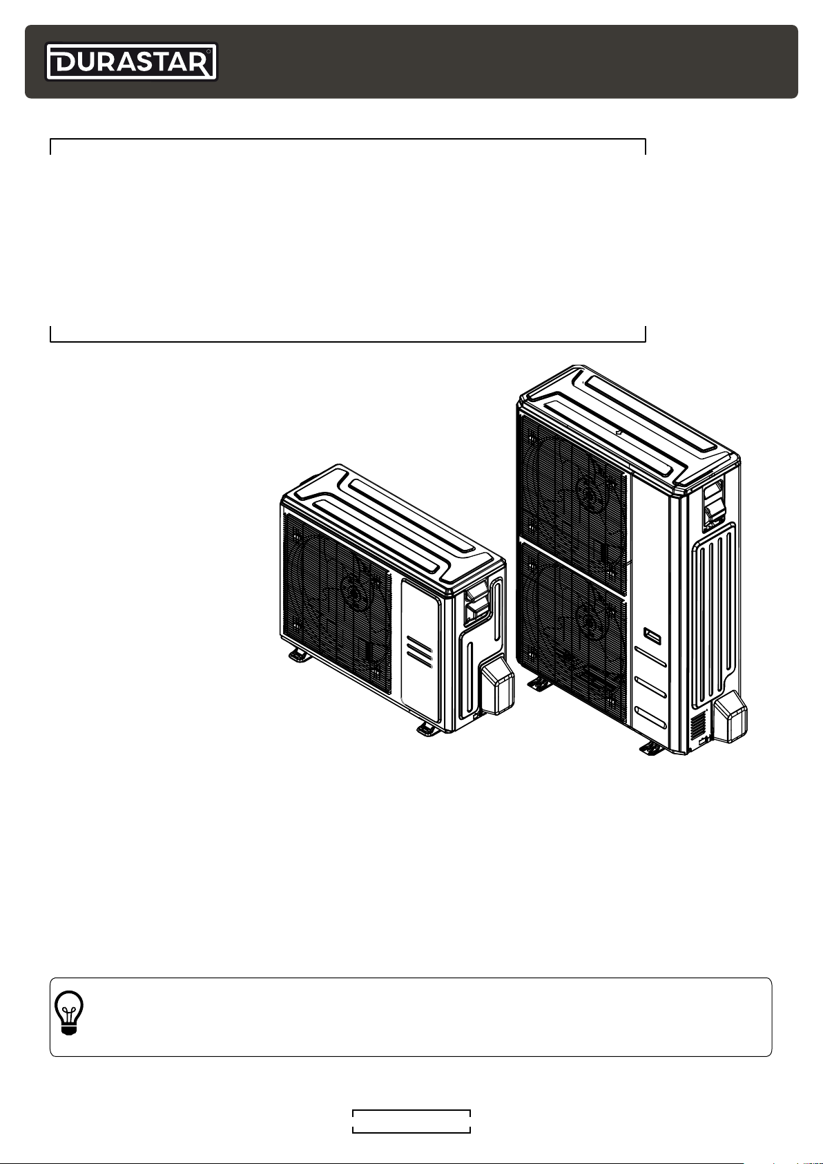
Single Zone Side-Discharge Heat Pump:
30K to 60K
DRA1U30S1A, DRA1U36S1A, DRA1U48S1A, DRA1U60S1A
208/230V 1ph 60Hz 24V / RS485 Communicating
Model Number:
Serial Number:
Purchase Date:
Installing Contractor Company Name:
TIP
Capture relevant information about your Durastar mini-split equipment before it is
installed and write it above for future reference.
DURASTAR.COM1
Page 2
R
TABLE OF CONTENTS
TABLE OF CONTENTS .....................................................................................................................................2
INTRODUCTION ..................................................................................................................................................3
WARNINGS ............................................................................................................................................................3
IMPORTANT SAFETY PRECAUTIONS ....................................................................................................4
OPERATING TEMPERATURES .................................................................................................................... 7
ACCESSORIES ......................................................................................................................................................8
PARTS IDENTIFICATION .................................................................................................................................9
OUTDOOR UNIT INSTALLATION ..............................................................................................................10
STEP 1: SELECT INSTALLATION LOCATION .....................................................................................10
STEP 2: INSTALL THE DRAIN JOINT ......................................................................................................11
STEP 3: MOUNT THE OUTDOOR UNIT ..................................................................................................12
REFRIGERANT PIPING CONNECTION ...................................................................................................13
SYSTEM EVACUATION .................................................................................................................................. 20
WIRING THE OUTDOOR UNIT ....................................................................................................................21
CONTROL LOGIC ..............................................................................................................................................24
POWER SPECIFICATIONS ............................................................................................................................24
FINAL CHECKS ................................................................................................................................................... 26
TEST RUN ..............................................................................................................................................................27
TROUBLESHOOTING ..................................................................................................................................... 28
LED DISPLAY ...................................................................................................................................................... 29
ERROR AND OPERATING CODES .......................................................................................................... 30
WIRING DIAGRAMS ..........................................................................................................................................31
JOB SITE INFORMATION SHEET ............................................................................................................. 33
DURASTAR.COM2
Page 3
INTRODUCTION
To better serve you, please do the following before contacting customer service:
• If you received a damaged product, immediately contact the retailer or dealer that sold you the
product.
• Read and follow this owner's manual carefully to help you use and maintain your air handler.
• Read the troubleshooting section of this manual as it will help you diagnose and solve common
issues.
• Visit us on the web at WWW.DURASTAR.COM to download product guides and up-to-date
information.
• If you need warranty service, our friendly customer service representatives are available via
email at [email protected] or by telephone at 1-888-320-0706.
WARNINGS
R
Symbols Used in This Manual
The warning symbol indicates cautionary information for the user. Extra care and
precautions should be taken to ensure the user's safety.
The pencil indicates any manufacturer notes relating to surrounding content. These may
include further clarifications or call-outs.
A light bulb symbol indicates suggested manufacturer tips for the user to get the most
out of the Durastar equipment and to accommodate the best user experience.
DURASTAR.COM
3
Page 4
R
IMPORTANT SAFETY PRECAUTIONS
Improper handling can cause serious damage or injury. Please read the following safety
information in its entirety.
Operation, Cleaning, and Maintenance Safety Precautions
• Children and people with reduced physical, sensory, or mental capabilities, or lack of experience
and knowledge, should only use this air handler if they are given supervision and instructions
concerning use of the air handler in a safe way and understand the hazards involved.
• Children should not play with the air handler.
• Never stick fingers, other body parts, or other objects into the air inlet or outlet. The internal fan
may be rotating at high speeds. This could result in injury.
• Installation and maintenance must be performed by qualified professionals. Otherwise, you may
experience personal injury or damage to the air handler and surrounding property.
• If an abnormal situation arises (like a burning smell), immediately turn off the air handler and
disconnect power at the circuit breaker immediately. Then contact your dealer or a qualified
professional for service.
• Do not climb onto or place objects on top of the outdoor unit.
• Do not install the air handler in a wet room such as a bathroom or laundry room. Too much
exposure to water could cause electrical components to short circuit.
• Do not operate the air handler with wet hands. This may cause electric shock.
• Turn off the device and disconnect the power before cleaning. Failure to do so can cause
electrical shock.
• Do not clean the air handler with excessive amounts of water.
• Do not clean the air handler with combustible cleaning agents. Combustible cleaning agents can
cause fire or deformation.
• Do not use flammable materials such as hair spray, lacquer, or paint near the air handler as they
may catch fire.
• Do not operate the air handler in places near combustible gases. Emitted gases may collect
around the air handler and cause an explosion.
• Do not use the air handler for any other purpose than its intended use.
• Turn off the air handler if you are not going to use it for a long time.
• Make sure that water can drain unhindered from the unit.
• Do not allow the air handler to operate for long periods of time with doors or windows open, or if
the humidity is very high.
• Do not expose your body directly to cool air for a prolonged period of time.
• If the air handler is used together with burners or other heating devices, thoroughly ventilate the
room to avoid oxygen deficiency and carbon monoxide build up.
• In certain environments, such as kitchens, server rooms, etc., the use of specially designed air
handler units is highly recommended.
• As with any mechanical equipment, contact with sharp sheet metal edges can result in personal
injury. Take care while handling this equipment and wear gloves and protective clothing.
DURASTAR.COM4
Page 5
Electrical Safety
WARNING
Before performing any electrical or wiring work, turn off the main power to the
system.
• The product must be properly grounded at the time of installation, or electrical shock may occur.
• If there is a serious safety issue with the power supply, stop work immediately. Explain your
reasoning to the client, and refuse to install the unit until the safety issue is properly resolved.
• For all electrical work, follow all local and national wiring standards, regulations, and the
Installation Manual. Connect cables tightly, and clamp them securely to prevent external forces
from damaging the terminal. Improper electrical connections can overheat and cause fire, and
may also cause shock. All electrical connections must be made according to the Electrical
Connection Diagram located on the panels of the indoor and outdoor units.
• All wiring must be properly arranged to ensure that the control board cover can close properly. If
the control board cover is not closed properly, it can lead to corrosion and cause the connection
points on the terminal to heat up, catch fire, or cause electrical shock.
R
• If connecting power to fixed wiring, an all-pole disconnection device which has at least 1/8"
(3mm) clearances in all poles, a leakage current that may exceed 10mA, a residual current
device(RCD) that has a rated residual operating current not exceeding 30mA, and a
disconnection must be incorporated in the fixed wiring in accordance with the wiring rules.
• Only connect the unit to an individual branch circuit. Do not connect another appliance to
that circuit.
• No other equipment should be connected to the same power circuit.
• Power voltage should be within 90-110% of rated voltage. Insufficient power supply can cause
malfunction, electrical shock, or fire.
• Installation of an external surge suppressor at the outdoor disconnect is recommended.
• The air handler’s circuit board (PCB) is designed with a fuse to provide over current protection.
The specifications of the fuse are printed on the circuit board.
• Do not let wires touch or rest against refrigerant tubing, the compressor, or any moving parts
within the unit.
• To avoid getting an electric shock, never touch the electrical components soon after the power
supply has been turned off.
• After turning on the power, always wait 10 minutes or more before you touch the
electrical components.
• Make sure that you do not cross your electrical wiring with your signal wiring. This may cause
distortion, interference or possibly damage to circuit boards.
• Connect the outdoor wires before connecting the indoor wires.
DURASTAR.COM
5
Page 6
R
Installation Safety
• Installation must be performed by an authorized dealer or specialist. Defective installation can
cause water leakage, electrical shock, or fire.
• Installation must be performed according to the installation instructions. Improper installation
can cause water leakage, electrical shock, or fire. (In North America, installation must be
performed in accordance with the requirement of NEC and CEC by authorized personnel only.)
• Contact an authorized service provider for repair or maintenance of this unit. This appliance shall
be installed in accordance with national wiring regulations.
• Only use the included accessories, parts, and specified parts for installation. Using non-standard
parts can cause water leakage, electrical shock, fire, and can cause the unit to fail.
• Install the unit in a firm location that can support the unit’s weight. If the chosen location cannot
support the unit’s weight, or the installation is not done properly, the unit may fall and cause
serious injury and damage.
• Install drainage piping according to the instructions in this manual. Improper drainage may
cause water damage to your home and property.
• For units that have an auxiliary electric heater, do not install the unit within three (3) feet of any
combustible materials.
• Do not install the unit in a location that may be exposed to combustible gas leaks. If combustible
gas accumulates around the unit, it may cause fire.
• Do not turn on the power until all work has been completed.
• When moving or relocating the air handler, consult experienced service technicians for
disconnection and re-installation of the unit.
• Excessive Weight Hazard - Use two (2) or more people when moving and installing the unit.
Failure to do so can result in back or other type of injury.
DURASTAR.COM6
Page 7
OPERATING TEMPERATURES
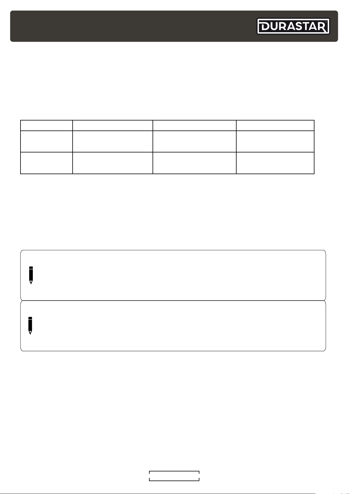
Your air handler is designed to operate in the following indoor and outdoor temperatures. When
your air handler is used outside of the following temperature ranges, certain safety features may
activate and turn off the unit to protect it from damage.
TEMPERATURE RANGES
COOL mode HEAT mode DRY mode
R
Indoor Air
Temperature
Outdoor Air
Temperature
60°F - 90°F
(16°C - 32°C)
5°F - 122°F
(-15°C - 50°C)
32°F - 86°F
(0°C - 30°C)
-13°F - 75°F
(-25°C - 24°C)
To further optimize the performance of your unit, do the following:
• Keep doors and windows closed.
• Limit energy usage by using TIMER ON and TIMER OFF features.
• Do not block air inlets or outlets.
• Regularly inspect and clean air filters.
NOTE
Your Durastar air handler's outdoor unit is equipped with a base pan heater, allowing it
to continue to operate at freezing temperatures as low as -13°F (-25°C). When outdoor
air temperatures are at or below 32°F (0°C), we strongly recommend keeping the unit
plugged in at all times to ensure smooth ongoing performance.
50°F - 90°F
(10°C - 32°C)
32°F - 122°F
(0°C - 50°C)
NOTE
Keep the room's relative humidity below 80%. If the air handler operates in excess of this,
the surface of the air handler may attract condensation. To help prevent condensation
from forming and dripping, set the vertical airflow louver to its maximum angle (vertically
to the floor) and set the fan to HIGH.
DURASTAR.COM
7
Page 8
R
ACCESSORIES
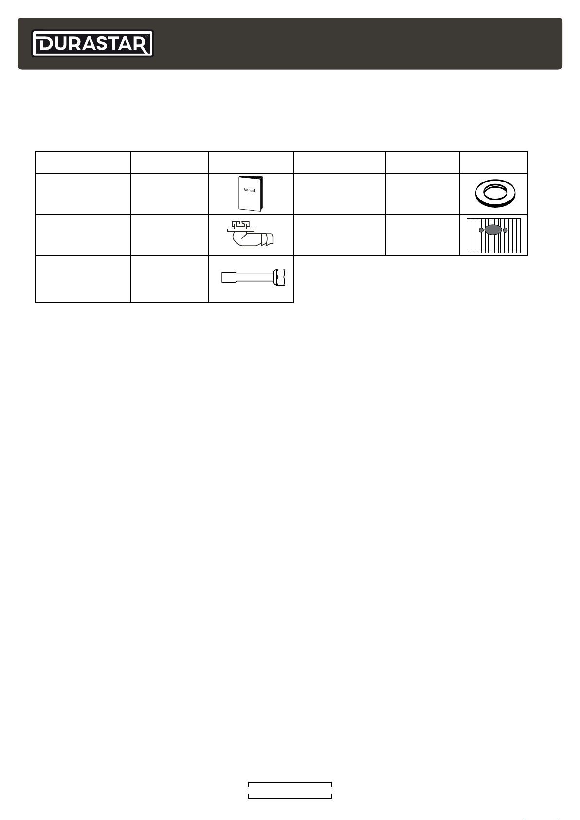
INCLUDED INSTALLATION ACCESSORIES
The air handler system comes with the following accessories.
Accessory Quantity Image Accessory Quantity Image
Installation
Manual
Drain Joint 1 Rubber Foot 4
Braze To Flare
Adapter
1 Drain Joint Seal 1
2
FIELD SUPPLIED INSTALLATION ACCESSORIES
The following installation accessories may be required and must be purchased separately.
• Refrigerant piping (line set)
• 3/8 Bi-flow Drier
• Indoor and outdoor connection/ thermostat wire
• Outdoor power supply cord and disconnect
• Drain pipe
• Pipe and cable wrapping tape
• Wall hole sleeve and cover
• Unit pad or wall bracket
• Wiring u-lugs
TOOLS NEEDED (OPTIONAL)
The following tools are required for installation.
• Phillips screwdriver
• Drill with 2 1/2" or 3 1/2" hole saw bit (depends on line set size)
• Vacuum pump
• HVAC manifold gauge set
• Micron Gauge
• Refrigerant leak detector
• Copper pipe cutter
• Flaring tool
• Burr reamer
• Crescent or spanner wrench
• Hexagonal wrench set
• Torque wrench
• Multimeter
• Electroprobe
• Level
• Hammer
• Wire strippers
• Wire crimper
DURASTAR.COM8
Page 9
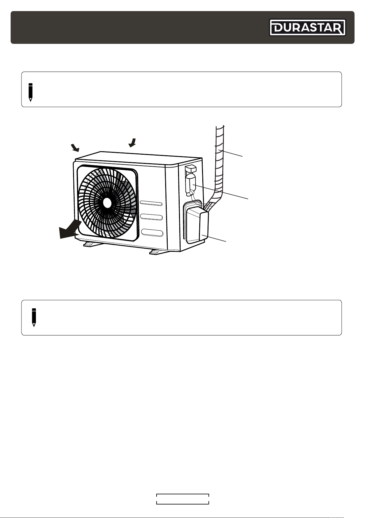
PARTS IDENTIFICATION
Signal Cable,
NOTE
The installation must be performed in accordance with the required local and national
standards. The installation may be slightly different in different areas.
R
Air Outlet
NOTE
Illustrations in this manual are for explanatory purposes. The actual shape of your minisplit equipment may vary slightly.
Air Inlets
Refrigerant Pipes,
and Drain Hose
Wiring Terminal
Valve Cover
DURASTAR.COM
9
Page 10
R
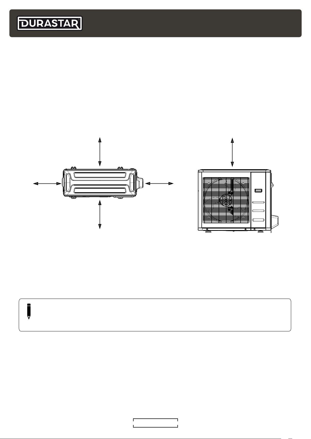
>4” (101mm)
OUTDOOR UNIT INSTALLATION
Installation Instructions
Install the unit following local codes and regulations. These may differ slightly between regions.
STEP 1: SELECT INSTALLATION LOCATION
Before installing the outdoor unit, you must choose an appropriate location. The following are
standards that will help you choose an appropriate location for the unit.
>4” (101mm)
>24” (610mm)
>24” (610mm)
>24” (610mm)
Proper installation locations meet the following standards:
• Meets all spatial requirements shown in installation space requirements above.
• Good air circulation and ventilation.
• Firm and solid location —the location can support the unit's weight and will not vibrate.
• Noise from the unit will not disturb others.
• Protected from prolonged periods of direct sunlight or rain.
NOTE
Where snowfall is anticipated, raise the unit above the base pad to prevent ice buildup
and coil damage. Mount the unit high enough to be above the average accumulated
area snowfall. The minimum height must be 18 inches.
DO NOT install unit in the following locations:
• Near an obstacle that will block air inlets and outlets.
• Near a public street, crowded areas, or where noise from the unit will disturb others.
• Near animals or plants that will be harmed by hot air discharge.
• Near any source of combustible gas.
• In a location that is exposed to large amounts of dust.
• In a location exposed to an excessive amount of salty air.
DURASTAR.COM10
Page 11
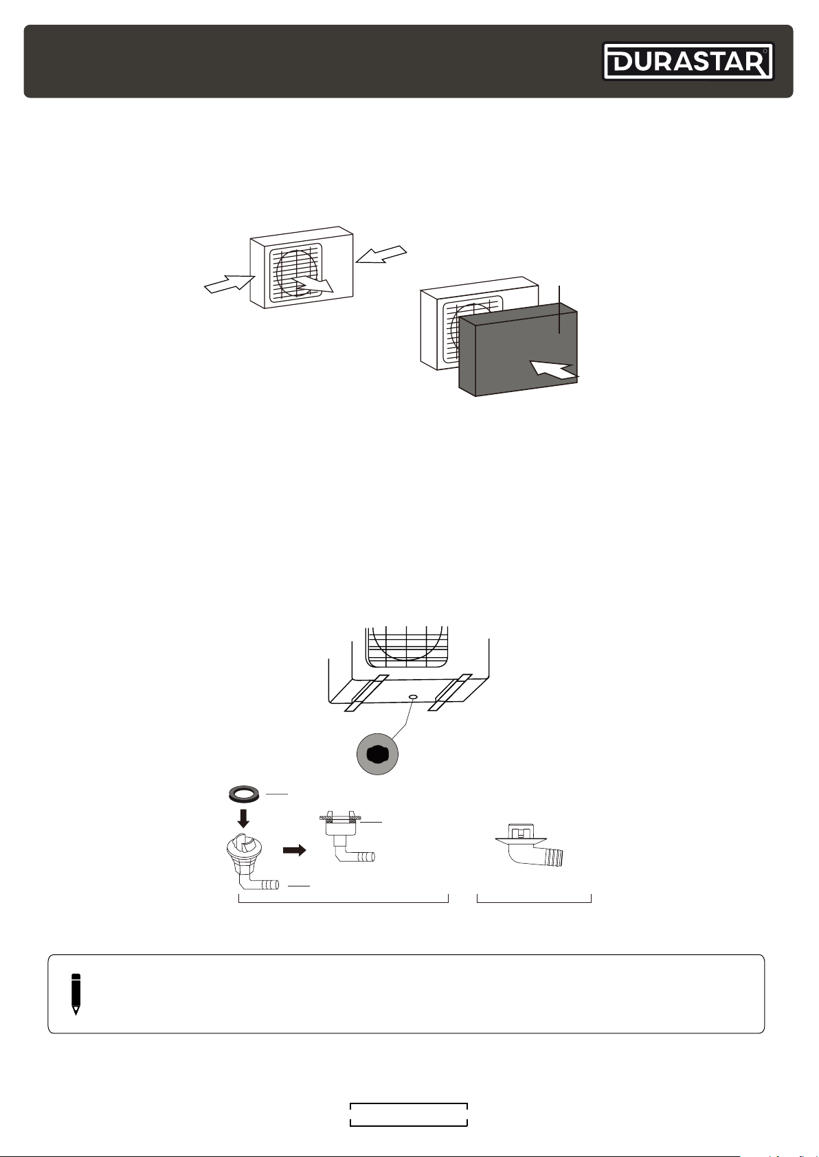
Special considerations for extreme weather
Strong
wind
If the unit is exposed to heavy wind, install the unit so that the air outlet fan is at a 90° angle to
the direction of the wind. If needed, build a barrier in front of the unit to protect it from extremely
heavy winds. See figures below.
Strong wind
Wind Baffle
Strong wind
If the unit is frequently exposed to heavy rain or snow
Build a shelter above the unit to protect it from rain or snow. Be careful not to obstruct airflow
around the unit.
R
STEP 2: INSTALL THE DRAIN JOINT
1. Fit the rubber seal on the end of the drain joint that will connect to the outdoor unit.
2. Insert the drain joint into the hole in the base pan of the unit.
3. Rotate the drain joint 90° until it clicks in place facing the front of the unit.
4. Connect a drain hose extension (not included) to the drain joint to redirect water from the unit
during heating mode.
Base pan hole of
outdoor unit
Seal
Seal
Drain joint
(A) (B)
NOTE
In cold climates, make sure that the drain hose is as vertical as possible to ensure swift
water drainage. If water drains too slowly, it can freeze in the hose and flood the unit.
DURASTAR.COM
11
Page 12
R
STEP 3: MOUNT THE OUTDOOR UNIT
NOTE
The unit should be mounted or raised above the maximum snowfall depth of the region.
Anchoring the Unit
The outdoor unit can be anchored to the ground or to a wall-mounted bracket (sold separately)
with bolts (M10). Mount the unit on a cement slab, condenser mounting pad, or other level surface
able to support the unit's weight. Do not place the unit directly on the ground. If using a wallmounting bracket, make sure the attached structure can support at least four times the unit's
weight.
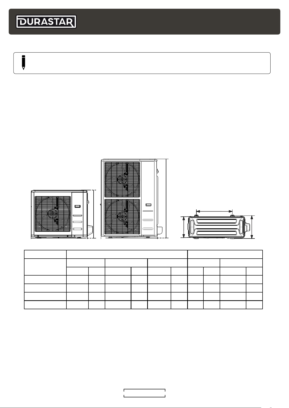
Unit Mounting Dimensions
The distance between their mounting feet varies by outdoor unit. Prepare the installation base of
the unit according to the dimensions below. In most cases, it may be easier to place the outdoor
unit in its correct location and mark the exact placement for the anchor holes.
H
A
H
D
Front View
OUTDOOR UNIT DIMENSIONS MOUNTING DIMENSIONS
W H D A B
MODEL
inch mm inch mm inch mm inch mm inch mm
DRA1U30S1A 37-1/4 946 31-15/16 810 16-3/16 410 26.5 673 5-7/8 403
DRA1U36S1A 37-1/4 946 31-15/16 810 16-3/16 410 26.5 673 5-7/8 403
DRA1U48S1A 37-1/2 952 52-1/2 1333 16-3/8 415 24 634 15-15/16 404
DRA1U60S1A 37-1/2 952 52-1/2 1333 16-3/8 415 24 634 15-15/16 404
Top View
B
DURASTAR.COM12
Page 13
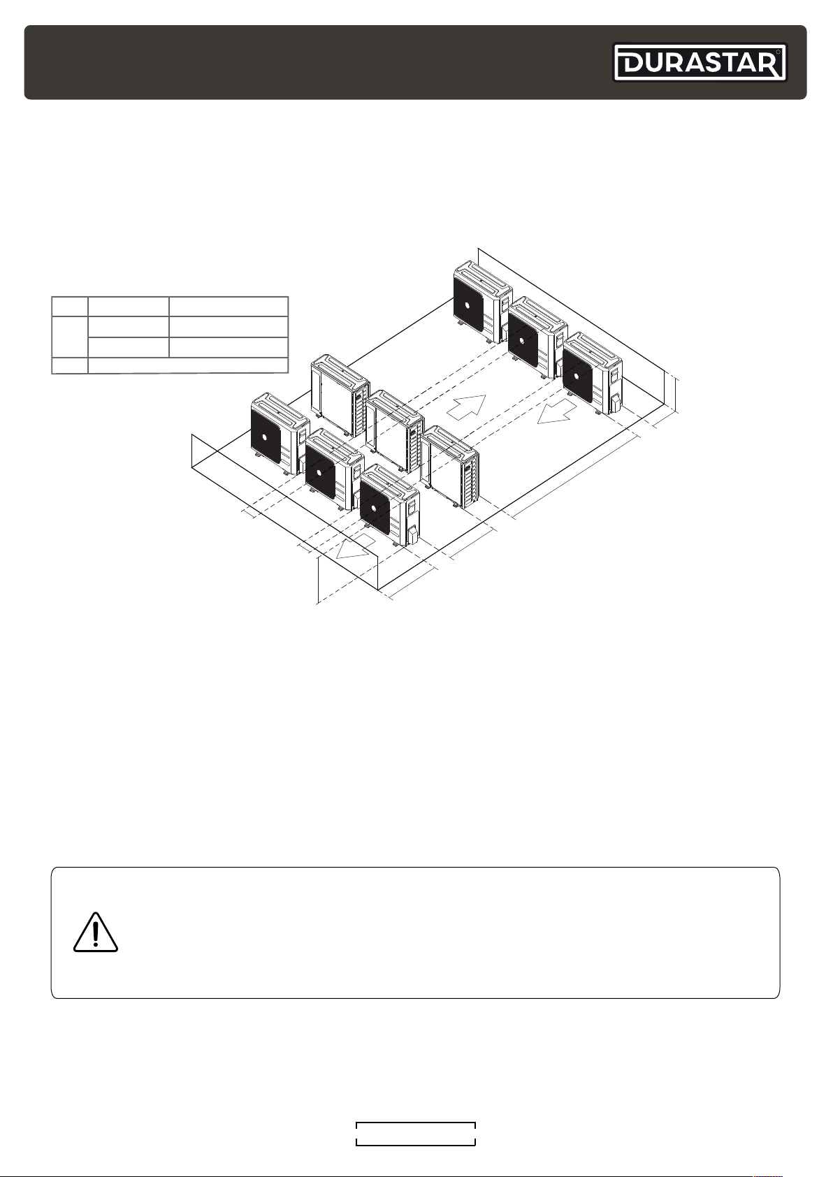
Installing multiple outdoor units
H = Outdoor unit height
L = Wall / Obstruction height
A = Required distance between unit and wall / obstruction
L
(1500mm)
If installing multiple outdoor units, refer to the diagram below for proper airflow clearances. Please
note it is still recommended to leave 24" between units for service.
L A
L ≤ H
L > H
L ≤ 1/2H
1/2H < L ≤ H
Can not be installed
≥9-13/16” (250mm)
≥11-13/16” (300mm)
A
R
≥9-13/16”
( m)
250m
≥9-13/16”
( m)
250m
H
REFRIGERANT PIPING CONNECTION
All field piping must be completed by a licensed technician and must comply with the local and
national regulations.
In the event of refrigerant leakage, measures should be taken to prevent the refrigerant
concentration in the room from exceeding the safe limit. If the refrigerant leaks and its
concentration exceeds its proper limit, hazards due to lack of oxygen may result. Ventilate the
area immediately.
WARNING
When connecting refrigerant piping, do not let substances or moisture other than
specified refrigerant enter the unit or pipes. Run nitrogen through the refrigerant
tubing when brazing to avoid carbon build up. The presence of foreign materials will
lower the unit's capacity and can cause abnormally high pressure in the refrigeration
system. This can result in explosion and personal injury.
≥59”
≥23-5/8”
00mm
(6 )
≥118” (3000mm)
DURASTAR.COM
13
Page 14
R
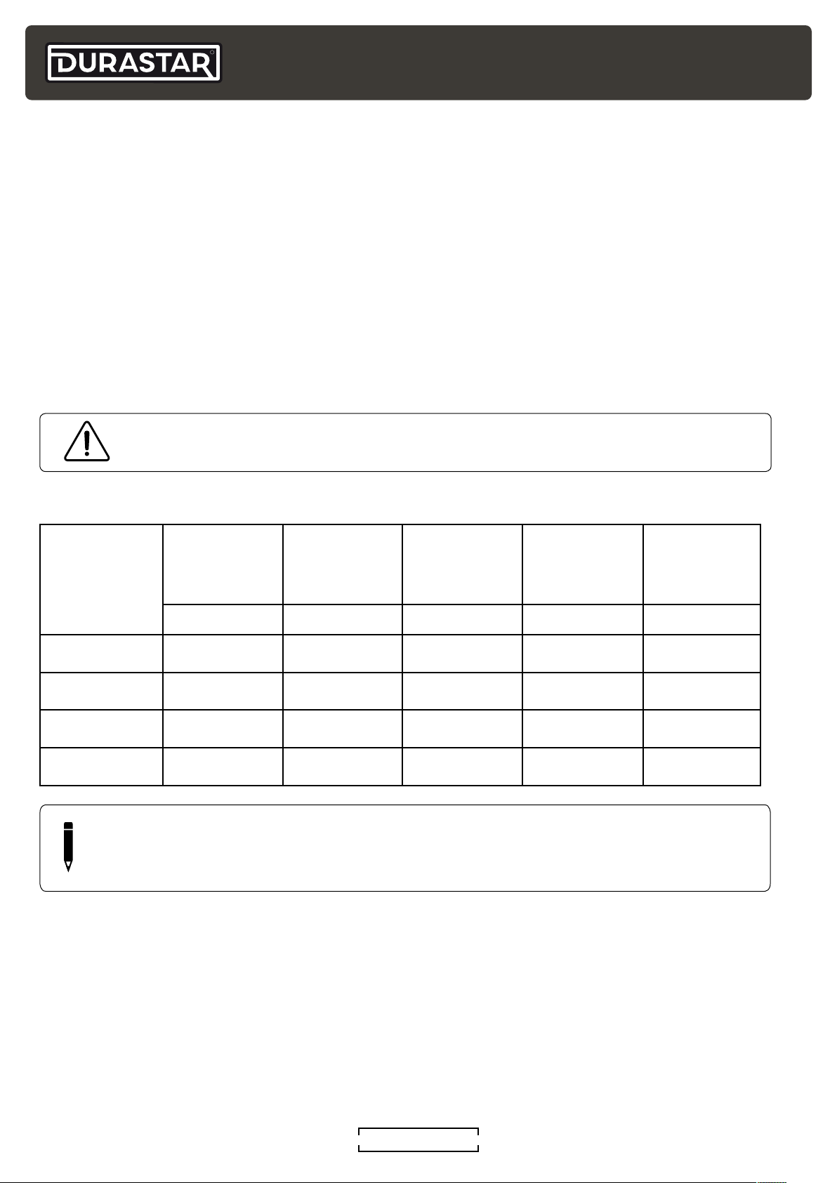
REFRIGERANT PIPE LENGTH
The length of refrigerant piping will affect the performance and efficiency of the unit. Nominal
efficiency is tested with a pipe length of 25 feet (7.6 meters). A minimum pipe run of 10 feet (3
meters) is required to minimize vibration and excessive noise.
ADDING ADDITIONAL REFRIGERANT
Each outdoor unit is factory charged with enough refrigerant to support up to 25' (7.5m) per zone.
This is based on a one way liquid line measurement from the outdoor unit to the indoor unit.
Systems with line sets that exceed this length will require additional refrigerant (see the following
chart). The refrigerant should be charged from the service port on the outdoor unit's low pressure
valve. Additional refrigerant information can be found in the SUBMITTAL DOCUMENTS at
WWW.SERVICE.DURASTAR.COM. Additional refrigerant can be calculated using the following
chart and formula: (Actual pipe length - Standard pipe length) x Additional Refrigerant Charge
WARNING
DO NOT mix refrigerant types.
Refrigerant Piping Specifications
Refrigerant
Connection
Capacity
k / x / (. ) . () () ()
k / x / (. ) . () () . ()
k / x / ( . ) . () () . ()
k / x/ ( . ) . () () . ()
NOTE
Size
in (L x G) ft (m) oz/ft (g/m) ft (m) ft (m)
Adapters are included with the indoor unit and outdoor unit to convert the flared fittings
to brazed if necessary.
Standard
Length w/
Precharged
Refrigerant
Additional
Refrigerant
Charge
Maximum
Length of
Piping
Maximum Rise
Length
DURASTAR.COM14
Page 15
Indoor unit/
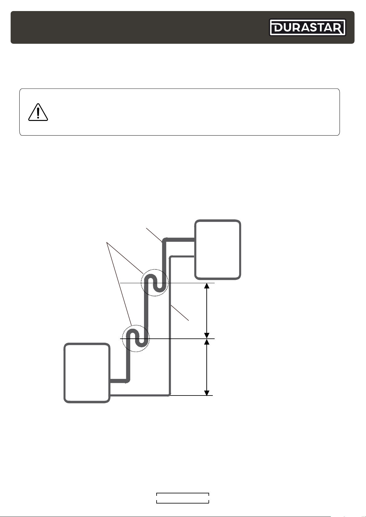
OIL TRAPS
Oil traps are necessary for the continued performance of the system if the indoor and outdoor
units are installed at significantly different heights.
CAUTION
If oil flows back into the outdoor unit’s compressor, this might cause liquid
compression or deterioration of oil return. Oil traps in the rising gas piping can
prevent this.
If the unit is less than 36000Btu/h an oil trap should be installed every 20ft (6m) of vertical
suction line rise.
If the unit is greater than 36000Btu/h an oil trap should be installed every 32.8ft (10m)of vertical
suction line rise.
R
Oil Trap
Indoor unit/
Outdoor unit
Suction Line
Outdoor unit
Unit < 36k then 20ft (6m)
Unit > 36k then 32ft (10m)
Liquid Line
Unit < 36k then 20ft (6m)
Unit > 36k then 32ft (10m)
DURASTAR.COM
15
Page 16
R
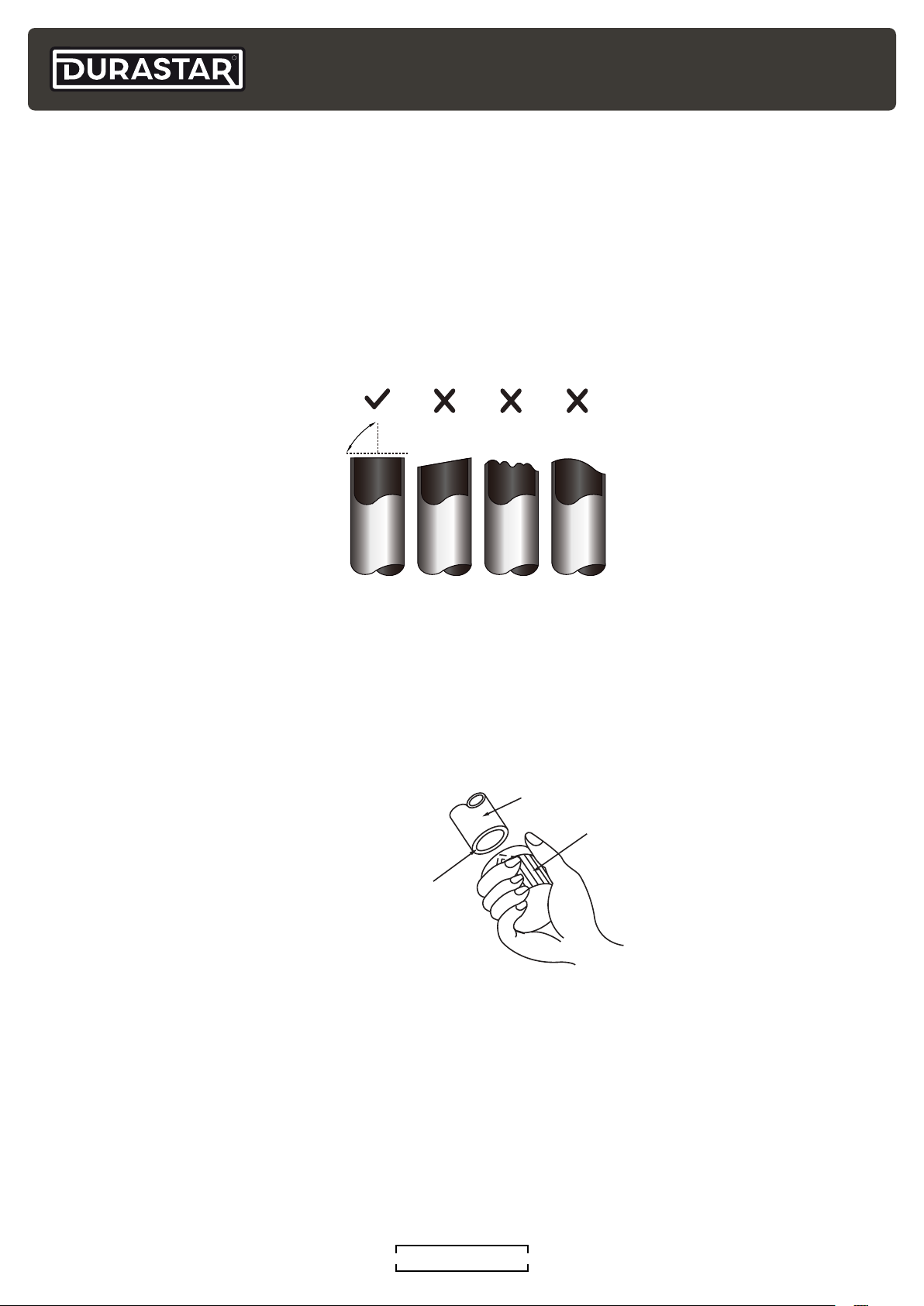
Oblique Rough Warped
90°
Pipe
Reamer
Point downward
REFRIGERANT PIPE CONNECTION INSTRUCTIONS
STEP 1: CUT PIPES
When preparing refrigerant pipes, take extra care to cut and flare them properly. This will ensure
efficient operation and minimize leaks and the need for future maintenance.
1. Measure the distance between the indoor and outdoor units.
2. Using a pipe cutter, cut the pipe length a little longer than the measured distance.
3. Make sure that the pipe is cut at a perfect 90 angle.
4. Do not damage, deform, or dent the pipe while cutting.
STEP 2: REMOVE BURRS
Burrs can affect the airtight seal of the refrigerant piping connection and must be completely
removed.
1. Hold the pipe at a downward angle to prevent burrs from falling into the pipe.
2. Using a reamer or deburring tool, remove all burrs from the cut section of the pipe.
DURASTAR.COM16
Page 17
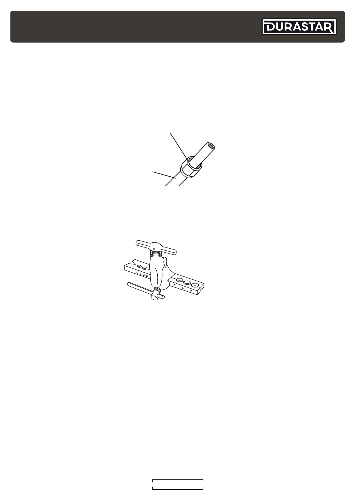
STEP 3: FLARE PIPE ENDS
Flare nut
Copper pipe
Proper flaring is essential to achieve an airtight seal.
1. After removing burrs from cut pipe, seal the ends with PVC tape to prevent foreign materials
from entering the pipe.
2. Sheath pipe with insulating material.
3. Place flare nuts on both ends of the pipe. Make sure they are facing in the right direction as
you cannot change their orientation after flaring.
R
4. Remove PVC tape from ends of pipe when ready to perform flaring.
5. Clamp flare form on the end of pipe. The end of the pipe must extend beyond the edge of the
flare form in accordance with the pipe extension table on the next page.
DURASTAR.COM
17
Page 18
R
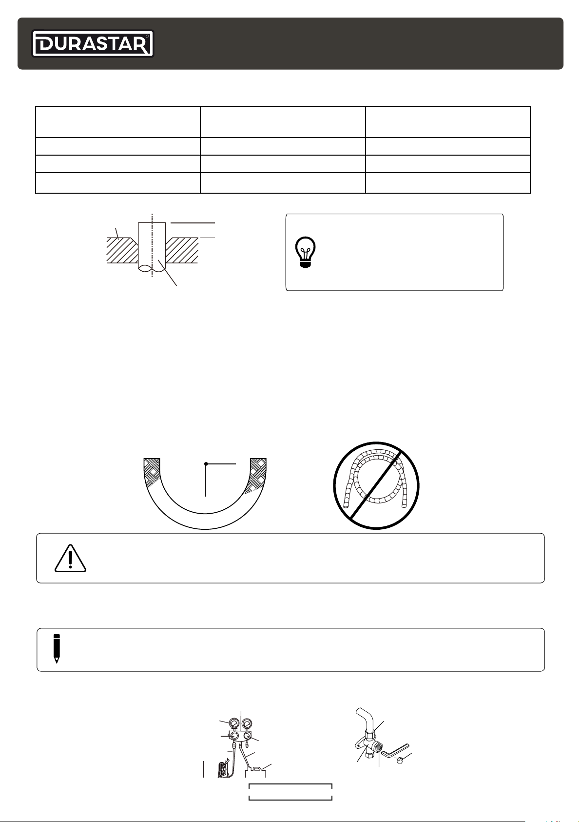
Flare form
Pipe
A
Manifold Gauge
Low pressure hose
Cap
Radius ~4” (10cm)
PIPE EXTENSION BEYOND FLARE FORM
Outer Diameter of Pipe
Inches (mm)
"A" Minimum Extension
Inches (mm)
"A" Maximum Extension
Inches (mm)
3/8" (9.5mm) 0.04" (1.0mm) 0.063" (1.6mm)
3/4" (19.1mm) 0.078" (2.0mm) 0.094" (2.4mm)
7/8" (22.0mm) 0.078" (2.0mm) 0.094" (2.4mm)
TIP: THICKNESS COMPARISON
• 0.0275" = A Thumbnail
• 0.04" = A Dime
• 0.078" = A Nickle
6. Place flaring tool onto the form.
7. Turn the handle of the flaring tool clockwise until the pipe is fully flared.
8. Remove the flaring tool and flare form, then inspect the pipe for cracks and even flaring.
STEP 4: CONNECT PIPES
When connecting refrigerant pipes, be careful not to use excessive torque or to deform the piping
in any way. You should first connect the low-pressure pipe, then the high-pressure pipe.
When bending connective refrigerant piping, the minimum bending radius is 4 inches (10cm). Do
not leave coils in the refrigerant line sets. Remove excess line length to ensure proper system
operation.
WARNING
Do not leave coils in the refrigerant line sets. All excess line length must be removed
to ensure proper system operation.
CONNECTING PIPING TO INDOOR UNIT
NOTE
It is advised to install a 3/8 bi-flow drier on the liquid line near the indoor unit.
1. Align the center of the two pipes that you will connect.
Low pressure
gauge
Low pressure
valve
High pressure
valve
Auxiliary hose
Vacuum pump
DURASTAR.COM18
Valve body
Flare nut
Valve stem
Page 19
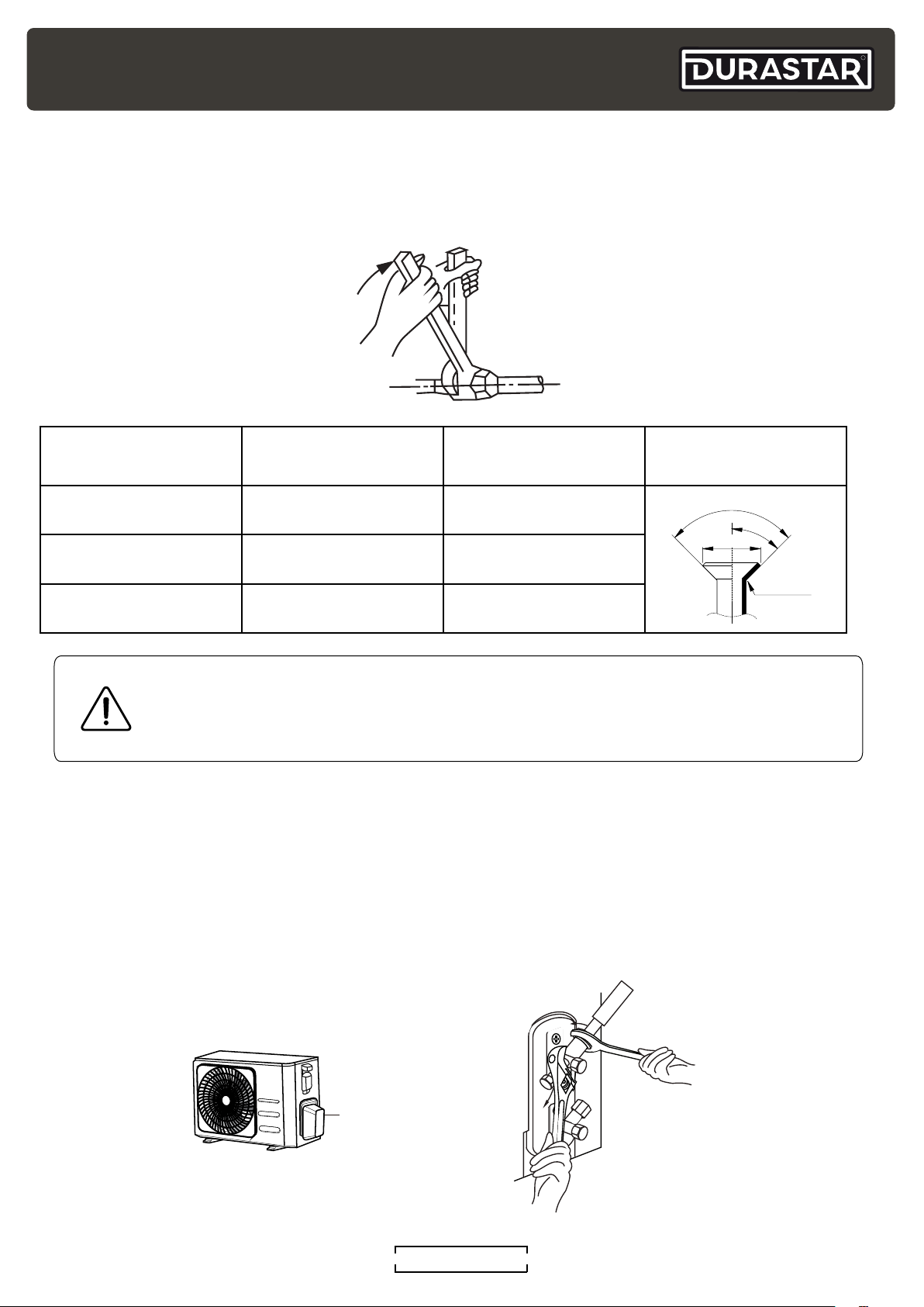
2. Tighten the flare nut as tightly as possible by hand.
°
3. Using a spanner, grip the nut on the unit tubing.
4. While firmly gripping the nut on the unit tubing, use a torque wrench to tighten the flare nut
according to the torque values in the table below. Loosen the flaring nut slightly, then tighten
again.
R
Outer Diameter of
Pipe Inches (mm)
3/8" (9.5mm) 23.6~28.8 (32~39) 0.52~0.53 (13.2~13.5)
3/4" (19.1mm) 49.4~74.5 (67~101) 0.91~0.93 (23.2~23.7)
Tightening Torque
lb-ft (Nm)
Flare Dimension "B"
Inches (mm)
Flare Shape
4
±
90
45
°
±
2
B
R 0.4~0.8
7/8" (22.0mm) 62.7~81.1 (85~110) 1.04~1.06 (26.4~26.9)
WARNING
Do not use excessive torque. Excessive force can break the nut or damage the
refrigerant piping. You must not exceed the torque requirements shown in the table
above.
CONNECTING PIPING TO OUTDOOR UNIT
1. Remove the valve cover on the side of the outdoor unit.
2. Remove the protective caps from the ends of the valves.
3. Align flared pipe end with each valve and tighten the flare nut as tightly as possible by hand.
4. Using a spanner, grip the body of the valve. Do not grip the nut that seals the service valve.
5. While firmly gripping the body of the valve, use a torque wrench to tighten the flare nut
according to the correct torque values in the table above.
6. Loosen the flare nut slightly, then tighten again.
7. Repeat steps 3-6 for the remaining pipe.
Valve cover
DURASTAR.COM
19
Page 20
R
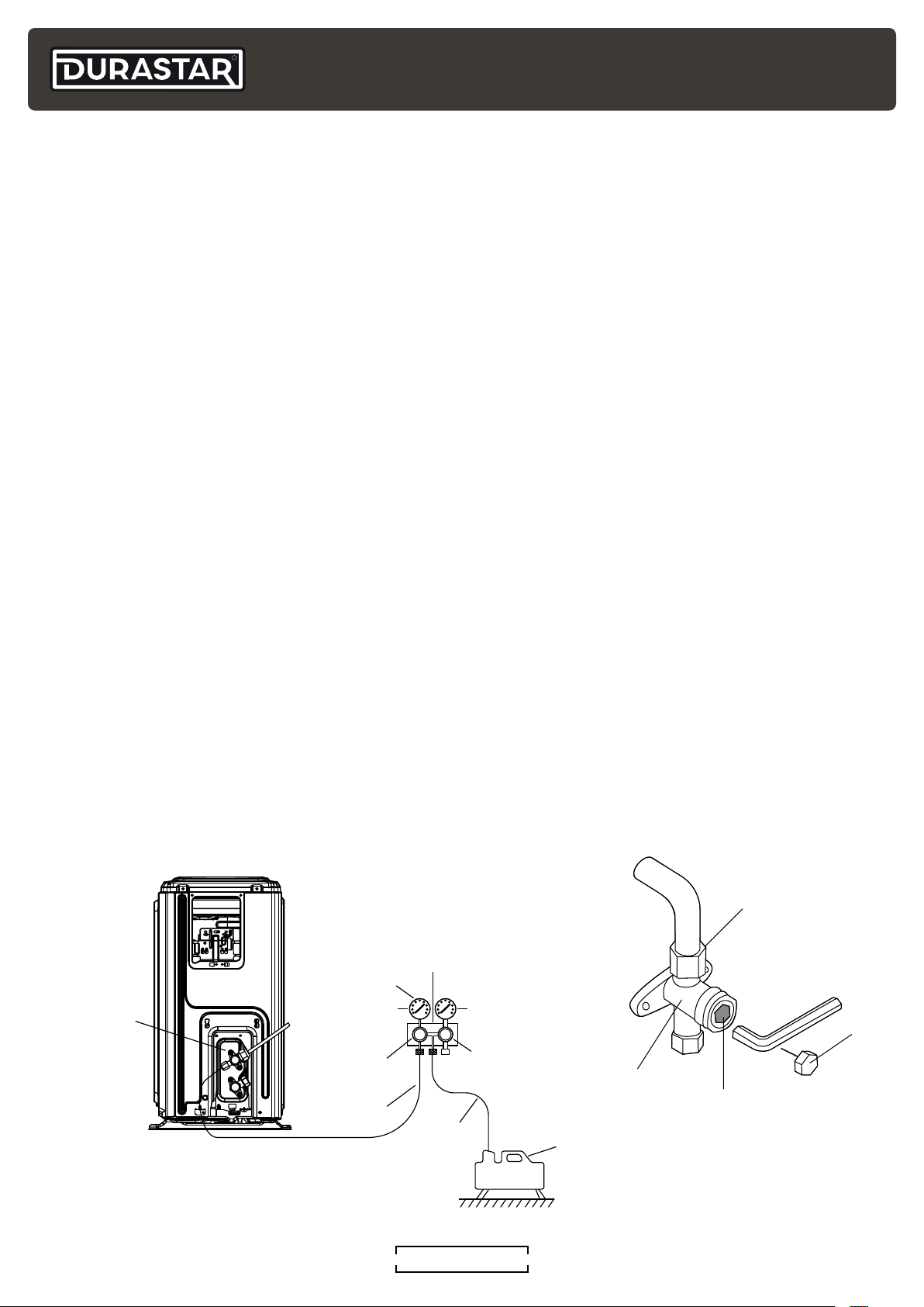
Outdoor unit
Vacuum
Cap
valve body
valve stem
SYSTEM EVACUATION
PREPARATIONS AND PRECAUTIONS
Air and foreign matter in the refrigerant system can cause abnormal rises in pressure, which can
damage the air handler, reduce energy efficiency, and cause injury. Use a vacuum pump and
manifold gauge to evacuate the refrigerant system, removing any non-condensible gas and
moisture from the system. Evacuation should be performed upon initial installation and if unit is
relocated.
BEFORE PERFORMING EVACUATION
1. Check to make sure the refrigerant pipes connecting the indoor and outdoor units are
connected properly and leak free.
EVACUATION INSTRUCTIONS
1. Connect the charge hose of the manifold gauge to service port on the outdoor unit’s low
pressure valve.
2. Connect another charge hose from the manifold gauge to the vacuum pump.
3. Open the Low Pressure side of the manifold gauge. Keep the High Pressure side closed.
4. Tighten refrigerant valve caps hand tight plus flat to ensure there are no vacuum leaks.
5. Turn on the vacuum pump to evacuate the system.
6. Run the vacuum for at least 15 minutes until the meter reads -76cmHG(-10 Pa) or 500 microns.
(the time will depend on the vacuum pump used)
7. Close the low pressure side of the manifold gauge, and turn off the vacuum pump.
8. Wait for 5 minutes, then check that there has been no change in system pressure.
9. If there is a change in system pressure, check to make sure the brazed and flare fittings are
sealed and refer to Gas Leak Check section. If there is no change in system pressure, you can
proceed.
10. If each unit is shipped with 25ft (7.6m) of refrigerant. If more is necessary, add it through the
low pressure service port on the unit.
11. After additional refrigerant is added if necessary, remove the charge hose from the service
port and unscrew the cap from the high pressure valve on the unit.
Low pressure
valve
Pressure hose
Charge hose
-76cmHg
Compound
gauge
Low
pressure
valve
or
Flare nut
Manifold
Gauge
Pressure
gauge
High
pressure
valve
Charge
hose
pump
DURASTAR.COM20
Page 21
12. Insert hexagonal wrench into the high pressure valve and open the valve by turning the wrench
in a 1/4 counterclockwise turn. Listen for gas to exit the system, then close the valve after 5
seconds. (Open the high pressure valve first. Do not try to force the valve to open further).
13. Watch the pressure gauge for one (1) minute to make sure that there is no change in pressure.
The pressure gauge should read slightly higher than atmospheric pressure.
14. Using hexagonal wrench, fully open both the high pressure and low pressure valves.
15. Tighten all valve caps to ensure no leaks. You may tighten it further using a torque wrench if
needed, being careful not to over tighten.
WIRING THE OUTDOOR UNIT
WARNING
Before performing any electrical or wiring work, turn off the main power to the
system.
R
WARNING
Failure to follow warnings may lead to equipment damage, injury or death.
Field line side wires may remain live, DO NOT perform service or maintenance
until the main disconnect is pulled.
WARNING
While connecting the wires, strictly follow the wiring diagram, and refer to the
nameplate for electrical information. Wire according to NEC and local codes.
The refrigerant circuit can become very hot. Keep the interconnection cable
away from the copper tube.
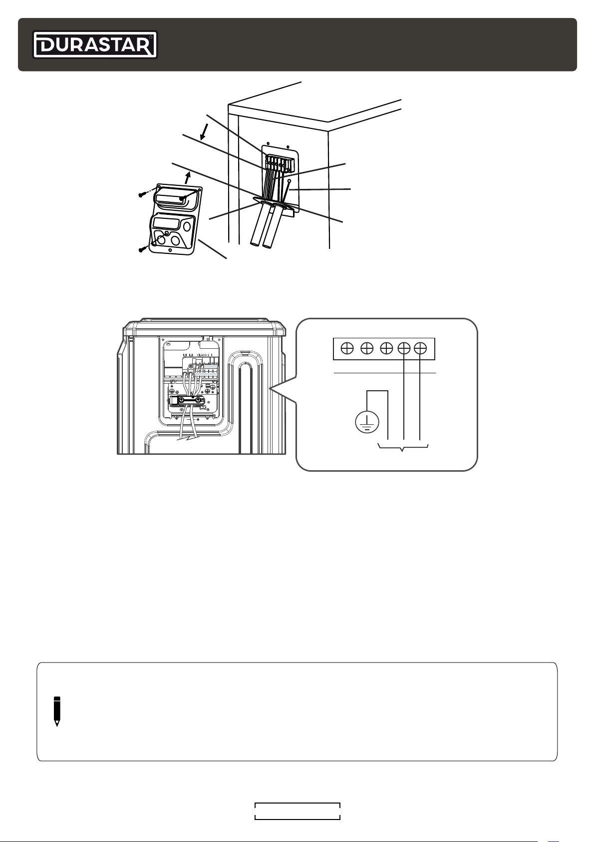
Connect the Power Cable
The size of the power supply cable, fuse, and switch needed is determined by the minimum circuit
ampacity (MCA) and maximum over current protection (MOCP) of system and the NEC and local
codes in your area. Refer to the nameplate and power specification chart.
1. Remove the electrical wiring cover.
2. Remove the caps on the conduit panel.
3. Be sure to cut the wire several inches longer than the required length for future maintenance.
4. Feed the wires through the conduit mounting panel and temporarily mount the conduit tubes
(sold separately).
5. Properly connect both the power supply to the corresponding terminals on the terminal block.
6. Ground the unit in accordance with local codes.
(See images on next page.)
DURASTAR.COM
21
Page 22
R
Terminal block
Over 1-9/16"
(40mm)
Select the appropriate conduit size
depending on the size of the wire.
Connecting cable
GG
Power supply cord
Conduit panel
Wire Cover
L1 L2
CLASS 2
B W D
R C Y1 Y2 L
TO POWER SOURCE
Connect the Signal Cable
The signal cable enables communication between the indoor and outdoor units. You must first
choose the right cable size before preparing it for connection. Run a continuous length of cable
and avoid splicing the cable.
Cable Sizing
Use the correct size cable depending on the communication type. See the indoor unit installation manual for more information.
• Non-polar RS485 Communication (S1/S2): 16 AWG stranded, shielded
• 24V Communication: 18 AWG/ 8 conductor thermostat wire
NOTE
The use of shielded communication or thermostat wire is not required, but is
recommended where separation from high voltage conductors can not be maintained, or
in areas with high electrical noise. The shield and drain conductor must be grounded at
the outdoor unit and stripped back and taped at the indoor unit. Grounding at both ends
results in an increase of noise transmitted onto the signal wires.
DURASTAR.COM22
Page 23
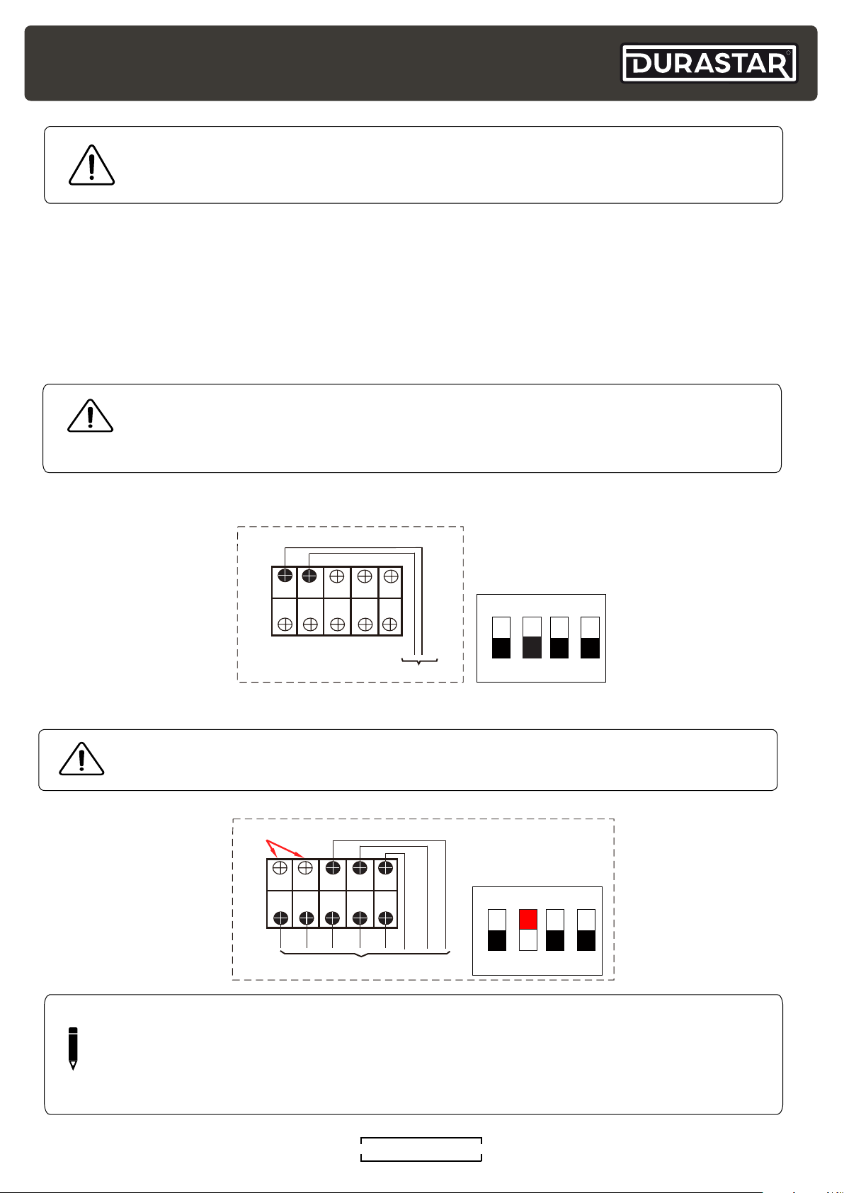
WARNING
Note: Outdoor 24V Connection
Pay attention to the live wire. While crimping wires, make sure you clearly distinguish
the Live (“L”) Wire from other wires.
Connecting the signal cable
1. Using wire strippers, strip the rubber jacket from both ends of cable to reveal about 1.5" (3840mm) of the wires inside.
2. Strip the insulation from the ends of the wires.
3. Using a wire crimper, crimp u-lugs on the ends of the wires.
4. Connect the low voltage wires according to desired connection method below. Refer to the
wiring diagram and the indoor unit installation manual for more information.
WARNING
All wiring work must be performed strictly in accordance with the wiring diagram.
Isolate the power supply leads from the communication wire leads with the strain
relief.
R
Connection Method 1 and 2: RS485 Communication
S1
S2 B W D
R C Y1 Y2 L
CN6
TO INDOOR UNIT
Connection Method 3: 24V Communication
WARNING
Do not connect 24V AC to S1 - S2, as this will damage the system.
DO NOT WIRE!!
S1
S2 B W D
R C Y1 Y2 L
S1
ON
1 2 3 4
S1
ON
CN6
TO 24V THERMOSTAT
NOTE
The "B" terminal energizes the reversing valve on call for heat. Please ensure that
thermostat configuration is set up for B functionality. Note: These methods are for use
with a Durastar outdoor unit with 24V communication or with a third party air handler,
cased coil, and gas furnace.
DURASTAR.COM
1 2 3 4
23
Page 24
R
Connect the Signal Cable cont.
5. Make sure any unused wired are properly insulated.
6. Permanently secure the conduit tubes to the conduit panel.
7. Replace the wire cover on the side of the unit, and screw it in place.
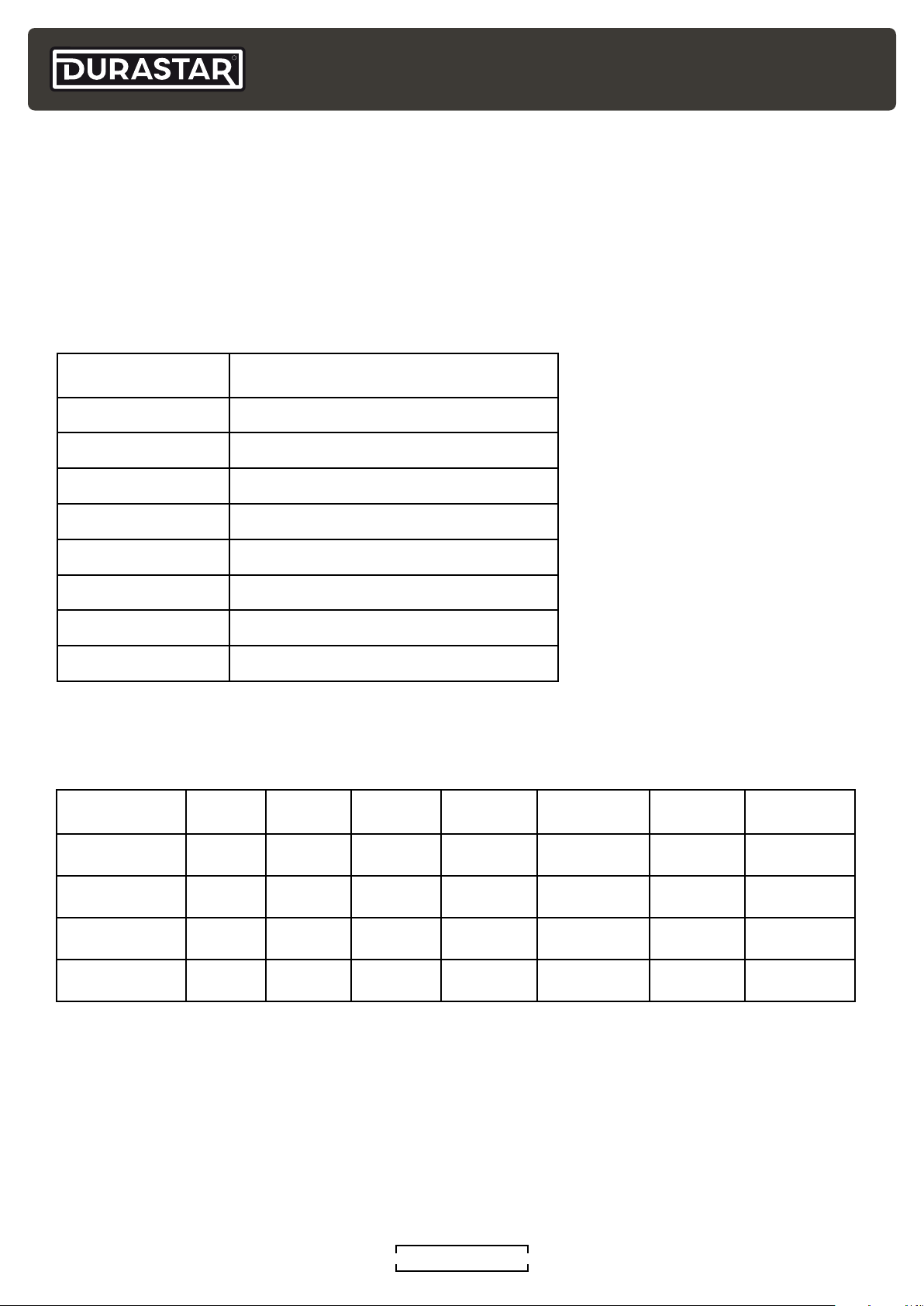
CONTROL LOGIC
Connector Purpose
R 24v Power Connection
C Common
Y1 Low Cooling
Y2 High Cooling
B Heating Reversing Valve
W Heating Control
D Defrost Control
L System Fault Signal
POWER SPECIFICATIONS
Model Number MCA (A) MOCP (A)
DRA1U30S1A 20 35 187-253 13.20 2835 12.40 2795
DRA1U36S1A 24 40 187-253 15.82 3560 15.80 3110
DRA1U48S1A 34 50 187-253 23.20 5320 22.50 5117
Voltage
Range (V)
Cooling
Current (A)
Cooling Input
Power (W)
Heating
Current (A)
Heating Input
Power (W)
DRA1U60S1A 34 60 187-253 29.00 6475 20.90 5085
DURASTAR.COM24
Page 25
Y1/Y2
two groups of electric heating at
function.
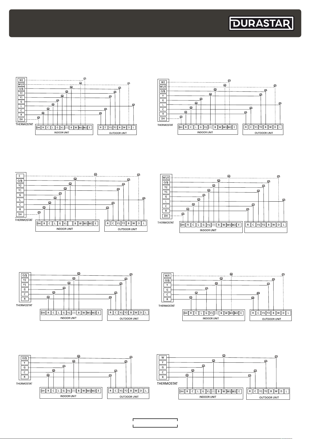
Connection Method 3 (cont.):
The following wiring diagrams are suitable for the air handler and outdoor with a 24V thermostat.
R
Wiring for 4H and 2C Thermostat
S4-2 Defaults ON: DH function off.
Turn switch OFF to activate DH
function.
S4-1 Defaults ON: W1 and W2
set for single stage Aux heat.
Turn OFF to separate stages.
Wiring for 3H and 1C Thermostat
S4-2 Defaults ON: DH function off.
Turn switch OFF to activate DH
function.
S4-1 Defaults ON: W1 and W2
set for single stage Aux heat.
Turn OFF to separate stages.
Wiring for 3H and 2C Thermostat Wiring for 3H and 2C Thermostat
S4-2 Defaults ON: DH function off.
Turn switch OFF to activate DH
Emergency heating (E) controls
the same tme.
Wiring for 2H and 2C Thermostat
Wiring for 1H and 1C Thermostat
S4-2 Defaults ON: DH function off.
Turn switch OFF to activate DH
function.
S4-1 Defaults ON: W1 and W2
set for single stage Aux heat.
Turn OFF to separate stages.
Wiring for 2H and 1C Thermostat
S4-1 Defaults ON: W1 and W2
set for single stage Aux heat.
Turn OFF to separate stages.
Wiring for 1H and 1C Thermostat
DURASTAR.COM
25
Page 26
R
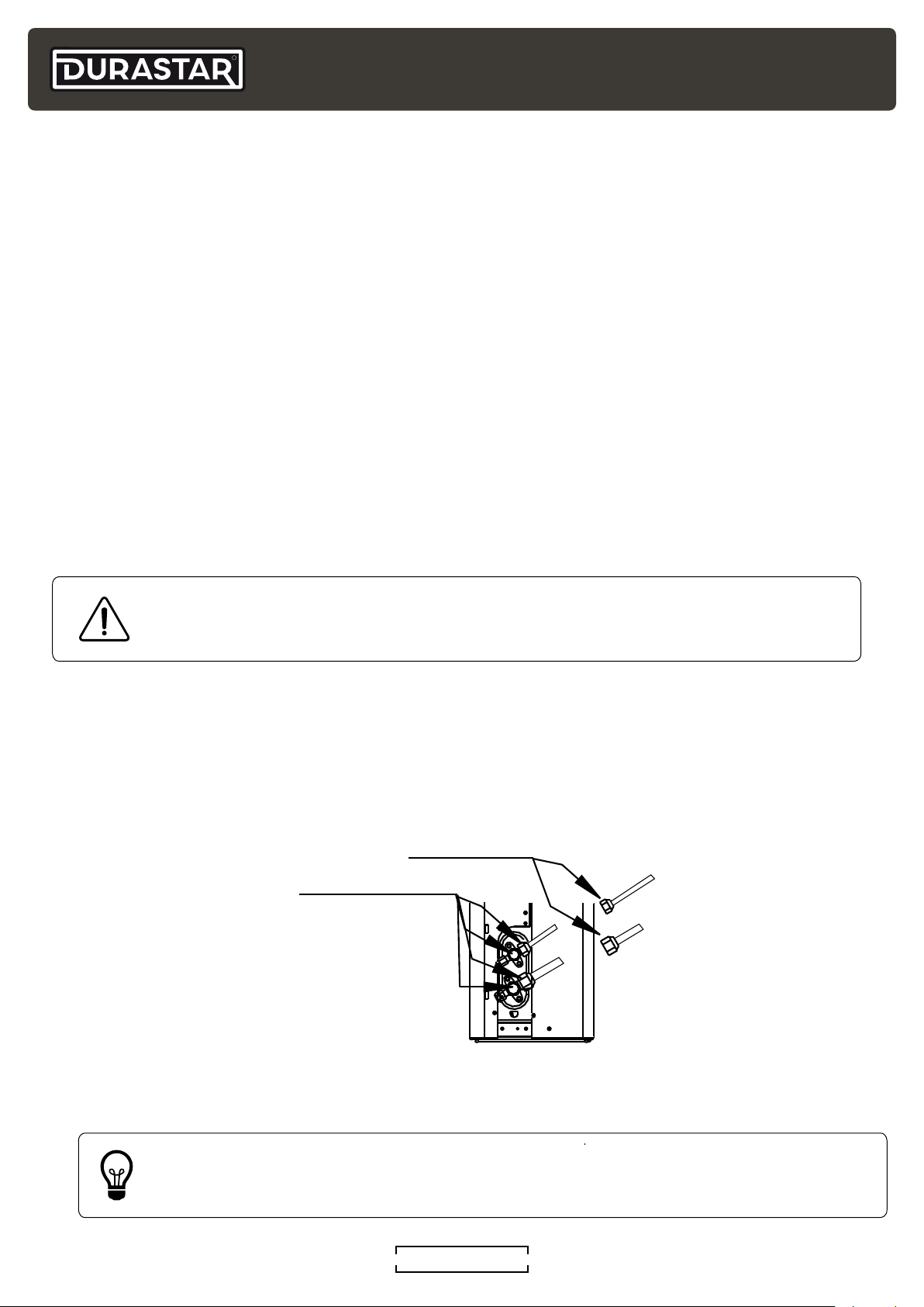
Check-point of indoor unit
Check-point of outdoor unit
FINAL CHECKS
BEFORE THE TEST RUN
Only perform the test run after you have completed the following steps:
• Electrical Safety Checks - Confirm that the unit's electrical system is connected and operating
correctly.
• Gas Leak Check - Check all flare nut connections and confirm the system is not leaking.
• Confirm that the low and high pressure valves are fully open.
• Check grounding work by measuring the grounding resistance by visual detection and with a
multimeter. The grounding resistance must be less than 0.1 Ω.
ELECTRICAL SAFETY CHECKS
After installation, confirm that all electrical wiring is installed in accordance with local and national
regulations, and according to this installation manual.
DURING TEST RUN
Using your multimeter, verify the voltage of the main power entering the system. If the main power
voltage is greater than ±10% of the name plate voltage, turn off the unit and immediately call a
licensed electrician to find and resolve the cause.
WARNING
RISK OF ELECTRICAL SHOCK - All wiring must comply with local and national
electrical codes, and must be installed by a licensed electrician.
GAS LEAK CHECK
There are two methods to check for gas leaks:
1. Soap and Water Method - Using a soft brush, apply a soapy water or liquid detergent to all
pipe connection points on the indoor and outdoor unit. The presence of bubbles indicates a
leak.
2. Leak Detector Method - If using a leak detector, refer to the device's operation manual for
proper usage instructions.
GAS LEAK CHECK POINTS
B
D
C
A
A: Low pressure stop valve
B: High pressure stop valve
C & D: Indoor unit flare nuts
TIP
Use the Durastar Job Site Information Sheet at the end of this manual as a
commissioning report to record your start up readings.
DURASTAR.COM26
Page 27
TEST RUN
TEST RUN INSTRUCTIONS
You should perform the test run for at least 30 minutes.
1. Connect power to the unit.
2. Press the ON/OFF button on the remote controller or wired thermostat to turn the unit on.
3. Press the MODE button to scroll through the following functions, one at a time:
• COOL - Select lowest possible temperature.
• HEAT - Select highest possible temperature.
4. Let each function run for 5 minutes and perform the following checks:
LIST OF CHECKS TO PERFORM [ X ]
Unit is Properly Grounded [ ]
All Electrical Terminals are Properly Covered [ ]
Indoor and Outdoor Units are Solidly Installed [ ]
All Pipe Connection Points Do Not Leak [ ]
Water Drains Properly from Drain Hose without leaks [ ]
All Piping is Properly Insulated [ ]
Unit Performs COOL Function Properly [ ]
Unit Performs HEAT Function Properly [ ]
There is no abnormal noise or vibration [ ]
Indoor Unit Responds to Remote Controller or Thermostat [ ]
R
5. Double check all pipe connections. During operation, the pressure of the refrigerant system will
increase. This may reveal leaks that were not present during the initial leak check. Take time
during the test run to recheck all pipe connection points. Refer to Gas Leak Check section for
instructions.
DURASTAR.COM
27
Page 28
R
TROUBLESHOOTING
SAFETY PRECAUTIONS
If ANY of the following conditions occurs, turn off your unit immediately!
• The power cord is damaged or abnormally warm
• You smell a burning odor
• The unit emits loud or abnormal sounds
• A power fuse blows or the circuit breaker frequently trips
• Water or other objects fall into or out of the unit
DO NOT ATTEMPT TO FIX THESE YOURSELF! CONTACT AN AUTHORIZED SERVICE PROVIDER
IMMEDIATELY!
COMMON ISSUES
The following problems are not a malfunction and in most situations will not require repairs.
ISSUE POSSIBLE CAUSES
Unit does not turn on
when pressing ON/OFF
button
The unit changes from
COOL/HEAT mode to
FAN mode
The unit has a 3-minute protection feature that prevents the unit
from overloading. The unit cannot be restarted within three minutes
of being turned off.
The unit may change its setting to prevent frost from forming on the
unit. Once the temperature increases, the unit will start operating in
the previously selected mode again.
The set temperature has been reached, at which point the unit
turns off the compressor. The unit will continue operating when the
temperature fluctuates again.
The indoor unit emits
white mist
Both the indoor and
outdoor units emit white
mist
The indoor unit makes
noises
In humid regions, a large temperature difference between the
room’s air and the conditioned air can cause white mist.
When the unit restarts in HEAT mode after defrosting, white mist
may be emitted due to moisture generated during the defrosting
process.
A rushing air sound may occur when the louver resets its position.
A squeaking sound may occur after running the unit in HEAT mode
due to expansion and contraction of the unit’s plastic parts.
Both the indoor unit and
outdoor unit make noises
Low hissing sound during operation: This is normal and is caused by
refrigerant gas flowing through both indoor and outdoor units.
Low hissing sound when the system starts, has just stopped running,
or is defrosting: This noise is normal and is caused by the refrigerant
gas stopping or changing direction.
Squeaking sound: Normal expansion and contraction of plastic and
metal parts caused by temperature changes during operation can
cause squeaking noises.
DURASTAR.COM28
Page 29
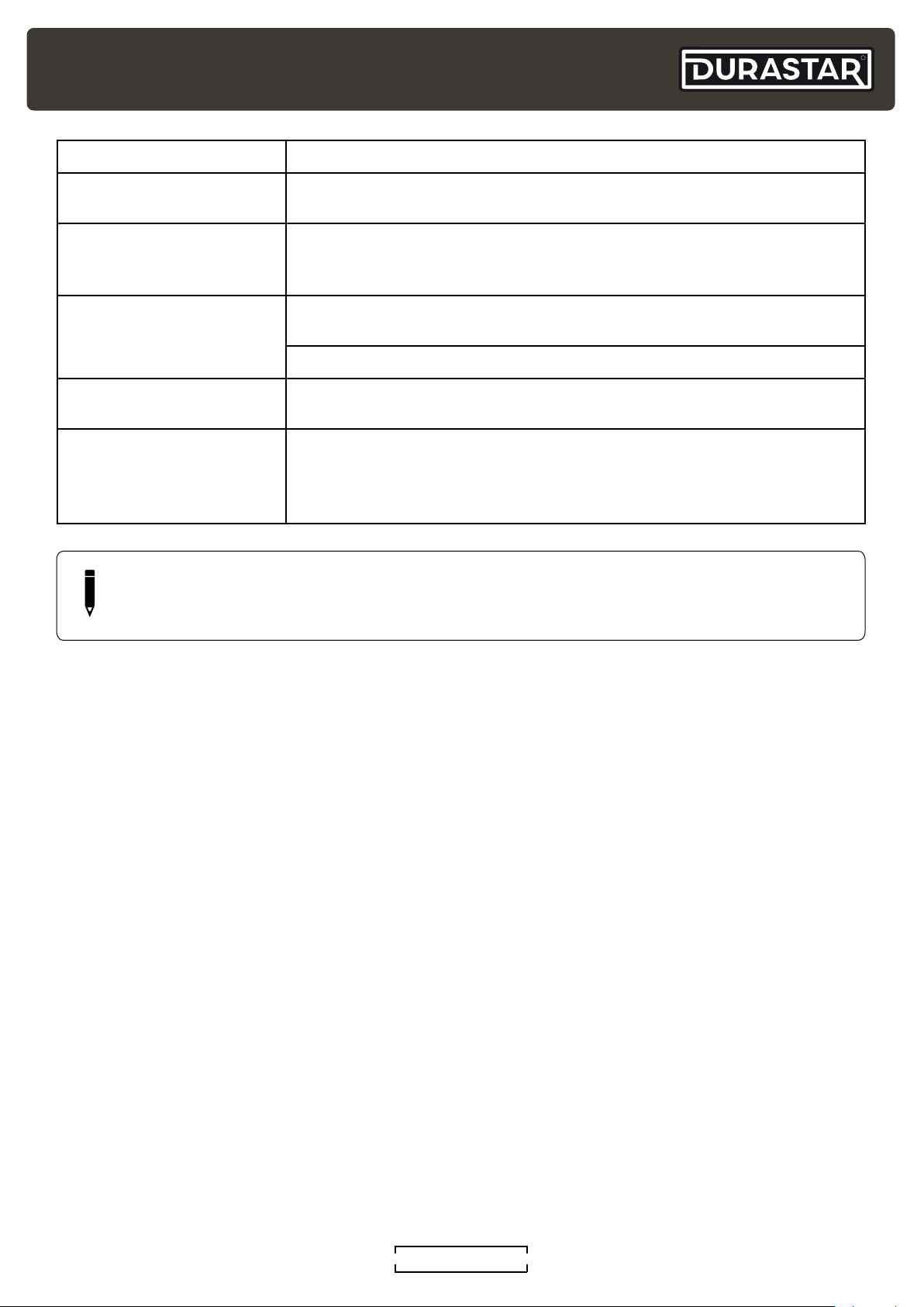
ISSUE POSSIBLE CAUSES
R
The outdoor unit makes
noises
Dust is emitted from
either the indoor or
outdoor unit
The unit emits a bad
odor
The fan of the outdoor
unit does not operate
Operation is erratic,
unpredictable, or unit is
unresponsive
NOTE
If your problem persists after performing the checks and diagnostics above, turn off your
unit immediately and contact an authorized service center.
The unit will make different sounds based on its current operating
mode.
The unit may accumulate dust during extended periods of nonuse, which will be emitted when the unit is turned on. This can be
mitigated by covering the unit during long periods of inactivity.
The unit may absorb odors from the environment (such as furniture,
cooking, cigarettes, etc.) which will be emitted during operations.
The unit’s filters have become moldy and should be cleaned.
During operation, the fan speed is controlled to optimize product
operation.
Interference from cell phone towers and remote boosters may
cause the unit to malfunction. In this case, try the following:
• Disconnect the power, then reconnect.
• Press ON/OFF button on remote control to restart operation.
LED DISPLAY
The control displays unit status as well as any active fault codes on the LED display. If the unit
is functioning normally, the LED will display current temperature set point. When a fault code is
active, the display will flash quickly the active fault code. Please refer to the error code table on
the following page.
DURASTAR.COM
29
Page 30
R
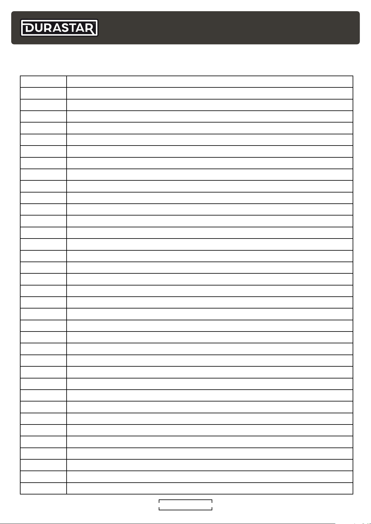
ERROR AND OPERATING CODES
Error Code Description
EC 51 Outdoor EEPROM malfunction
EL 01 Indoor / outdoor units communication error
EL 16 Communication malfunction between adapter board and outdoor main board
PC 00 IPM module protection
PC 02 Top temperature protection of compressor or IPM module
PC 06 Temperature protection of compressor discharge
PC 08 Outdoor overcurrent protection
PC 0A High temperature protection of condenser
PC 0F PFC module protection
PC 10 Outdoor unit low AC voltage protection
PC 11 Outdoor unit main control board DC bus high voltage protection
PC 12 Outdoor unit main control board DC bus high voltage protection /341 MCE error
PC 30 High pressure protection
PC 31 Low pressure protection
PC 40 Communication malfunction between IPM board and outdoor main board
PC 41 Outdoor compressor current sampling circuit failure
PC 43 Outdoor compressor lack phase protection
PC 44 Outdoor unit zero speed protection
PC 45 Outdoor unit IR chip drive failure
PC 46 Compressor speed has been out of control
PC 49 Compressor overcurrent failure
EC 52 Condenser coil temperature sensor T3 is in open circuit or has short circuited
EC 53 Outdoor room temperature sensor T4 is in open circuit or has short circuited
EC 54 Compressor discharge temperature sensor TP is in open circuit or has short circuited
EC 57 Refrigerant pipe temperature sensor error
EC 5C High pressure sensor is in open circuit or has short circuited
EC 71 Over current failure of outdoor DC fan motor
EC 72 Lack phase failure of outdoor DC fan motor
EC 73 Zero-speed failure of outdoor DC fan motor
EC 07 Outdoor fan speed has been out of control
PC 0L Low ambient temperature protection
LC 06 High temperature protection of IPM module
EC 55 Outdoor IPM module temperature sensor fault
PH 90 High temperature protection of evaporator
PH 91 Low temperature protection of evaporator
DURASTAR.COM30
Page 31
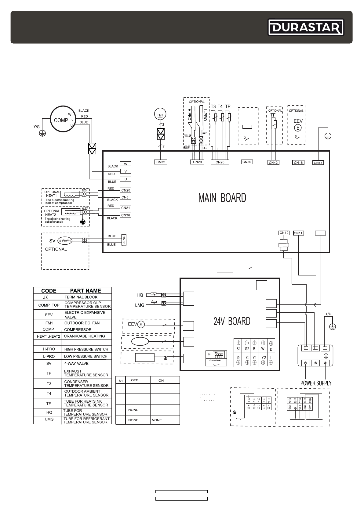
WIRING DIAGRAMS
DRA1U30S1A & DRA1U36S1A
R
16022000036170
OPTIONAL
COMP_TOP
Y/G
NOTE:Four-way valve
is used in the cooling
& heating unit only
CT1
AC CURRENT DETECTOR
SUCTION
OPTIONAL
DCF
OPTIONAL
GY
OPTIONAL
INDOOR UNIT
1
THROTTLING
INDOOR AND
2
OUTDOOR MODE
3
4
SUCTION
TEMP. SENSOR
REFRIGERANT
TEMP. SENSOR
1-WAY SOLENOID
VALVE
HIGH PRESSURE
SWITCH
BLACK
WHITE
6
2
OUTDOOR UNIT
THROTTLING
OUTDOOR UNIT
ONLY MODE
PRESSURE
COMPENSATION
PRESSURE
SENSOR
YL
CN11
CN28
CN5
ON
S1
1
2 3
CN38
ON~OFF
4
Notes:
This symbol indicates
the element is optional,
the actual shape shall
be prevail.
3
CN9
CN6
INDOOR AND
OUTDOOR MODE
CN6
TO INDOOR UNIT
CT1
BROWN(RED)
YELLOW
CN7
BLUE(BLACK)
CN4
RED(BROWN)
CN3
OUTDOOR UNIT
ONLY MODE
CN6
CN4
BLUE(BLACK)
(1)L1(2)
JX1
L2
TO 24V THERMOSTAT
YELLOW
DURASTAR.COM
31
Page 32
R
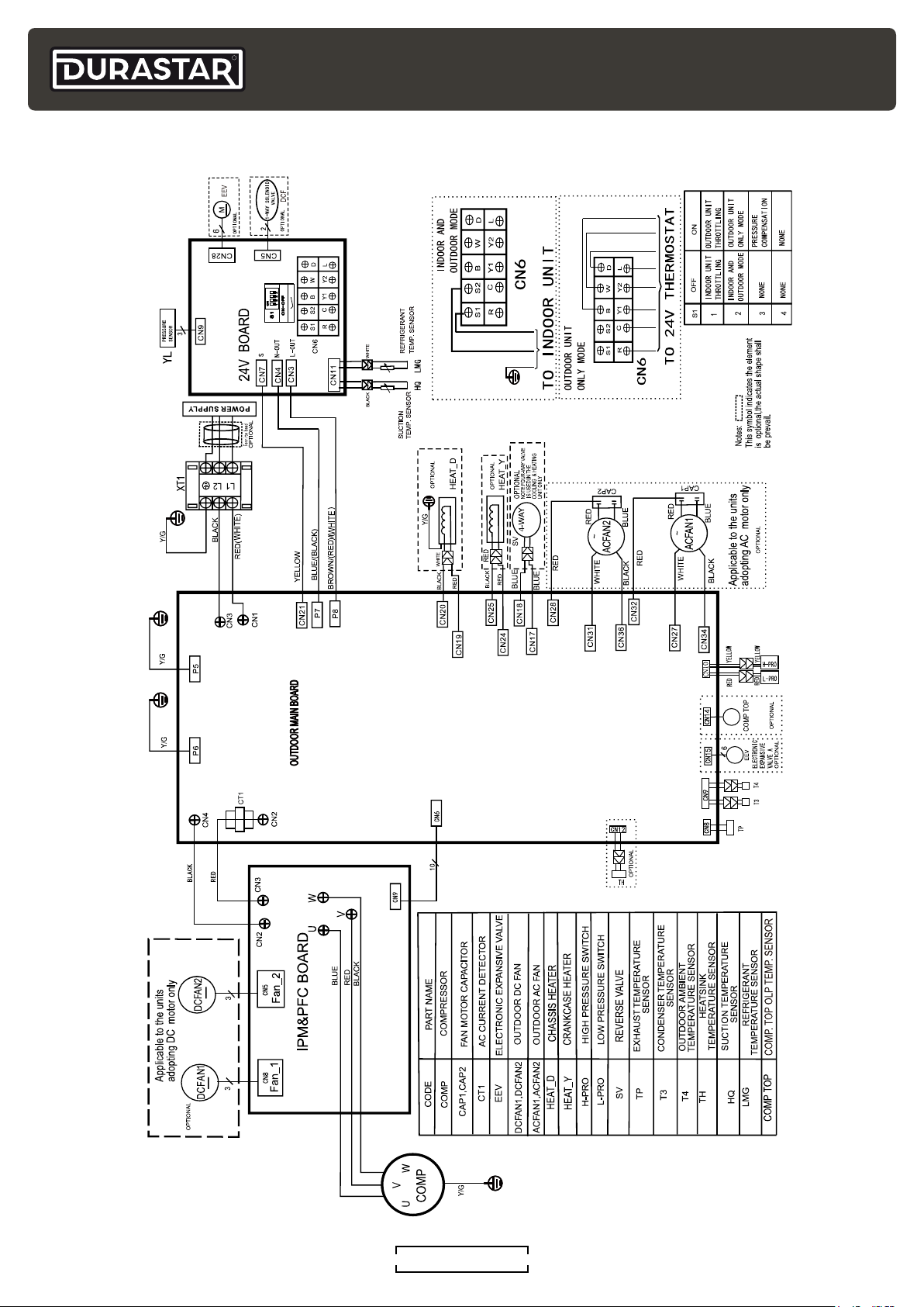
DRA1U48S1A & DRA1U60S1A
DURASTAR.COM32
Page 33
JOB SITE INFORMATION SHEET
Site Information
Job Name: _____________________________________________ Installation Date: _________________
Address: ______________________________ City: _____________________ State: ______ Zip: ________
Phone: ________________________ Email: ____________________________________________________
Contractor Information
Contractor Name: _____________________________ Technician Name: __________________________
Address: ______________________________ City: _____________________ State: ______ Zip: ________
R
Phone: ________________________ Email: ____________________________________________________
Outdoor Unit (ODU) Information
ODU Model #: ____________________________ ODU Serial #: ___________________________________
Unit Location: ____________________________________________________________________________
_________________________________________________________________________________________
Indoor Unit (IDU) Information
IDU Model #: _____________________________ IDU Serial #: ____________________________________
Unit Type: ___________________________ Unit Location: _______________________________________
_________________________________________________________________________________________
Refrigerant Line Size (Circle Liquid and Gas Line): 1/4" 3/8" 1/2" 5/8"
Line Set Length: ________________
DURASTAR.COM
33
Page 34
R
Outdoor Electrical Readings
Line Power Wire Color: L1 __________________ L2 __________________ G _____________________
Line Voltage (Power Off): L1 to L2 _____________ L1 to G _____________ L2 to G ________________
Line Voltage (Power On): L1 to L2 _____________ L1 to G _____________ L2 to G ________________
Outdoor to Indoor Electrical Readings
IDU Power/Control Wire Color: 1 __________________ 2 __________________ 3 ___________________
Voltage Readings: 1-2 ___________ AC 2-3 ___________DC
Outdoor Thermal Readings
ODU Discharge: _________°F OD Ambient: _________°F
Gas Line Saturation: _________°F Liquid Line Saturation: _________°F
Indoor Electrical Readings
IDU Power/Control Wire Color: 1 __________________ 2 __________________ 3 ___________________
Voltage Readings: 1-2 ___________ AC 2-3 ___________DC
Indoor Thermal Readings
Return Air: _________°F Supply Air: _________°F Room Air: _________°F
DURASTAR.COM34
Page 35
THIS PAGE INTENTIONALLY LEFT BLANK.
R
DURASTAR.COM
35
Page 36
R
THIS PAGE INTENTIONALLY LEFT BLANK.
©2023 Durastar
DURASTAR.COM36
V1.0 0923
 Loading...