

Page 1
MODEL :
48HF201CGT
www.tsicustomerservice.com
Twin-Star International, Inc; Delray Beach, FL 33445
Made in China • Printed in China • Fabricado en China • Impreso en China • Fabriqué en China • Imprimé en Chine
1-888-674-7517
1
www.tsicustomerservice.comA353
Page 2

Table of Contents
Safety Information ..................................................... 3
Warranty .....................................................................4
Pre-Operation ............................................................5
Pre-Assembly .............................................................6
Hardware Included ................................................... 6
Product Specications ....................................................... 6
Tools Required ................................................................... 6
Package Contents .............................................................. 7
Installation Options ................................................... 8
Wall Mounting ...........................................................9
Pedestal Base .................................................................. 13
Fuel Bed Setup Instructions............................................. 15
Operation .................................................................16
FCC/IC Information ......................................................... 19
Care & Cleaning ....................................................... 19
Troubleshooting ....................................................... 20
Replacement Parts .................................................. 21
A353
2
www.tsicustomerservice.com
Page 3
IMPORTANT INSTRUCTIONS
When using electrical appliances, basic precautions should always be followed to reduce the risk of re, electrical shock, and injury to
persons including the following:
1. Read all instructions before using this appliance.
2. This appliance is hot when in use. To avoid burns, do not let bare skin touch hot surfaces. If provided, use handles when moving
this appliance. Keep combustible materials, such as furniture, pillows, bedding, papers, clothes and curtains at least 3 feet (0.9 m)
from the front of this appliance and keep away from the sides and the rear. WARNING: In order to avoid overheating,
do not cover the heater.
3. CAUTION: Never leave the heater operating unattended. Extreme caution is necessary if unsupervised children or invalids are
nearby.
4. The appliance is not to be used by children or persons with reduced physical, sensory or mental capabilities, or lack of experience
and knowledge, unless they have been given supervision or instruction.
5. Always unplug this appliance when not in use.
6. Do not operate any heater with a damaged cord or plug or after the appliance malfunctions, or if it has been dropped or damaged
in any manner.
7. If the supply cord is damaged, it must be replaced by the manufacturer, its service agent or similarly qualied persons in order to
avoid a hazard.
8. Do not use outdoors.
9. This heater is not intended for use in bathrooms, laundry areas and similar indoor locations. Never locate this appliance where it
may fall into a bathtub or other water container.
10. Do not run cord under carpeting. Do not cover cord with throw rugs, runners or the like. Arrange cord away from trafc areas and
where it will not be tripped over.
11. To disconnect this appliance, turn controls to the off position, then remove plug from outlet.
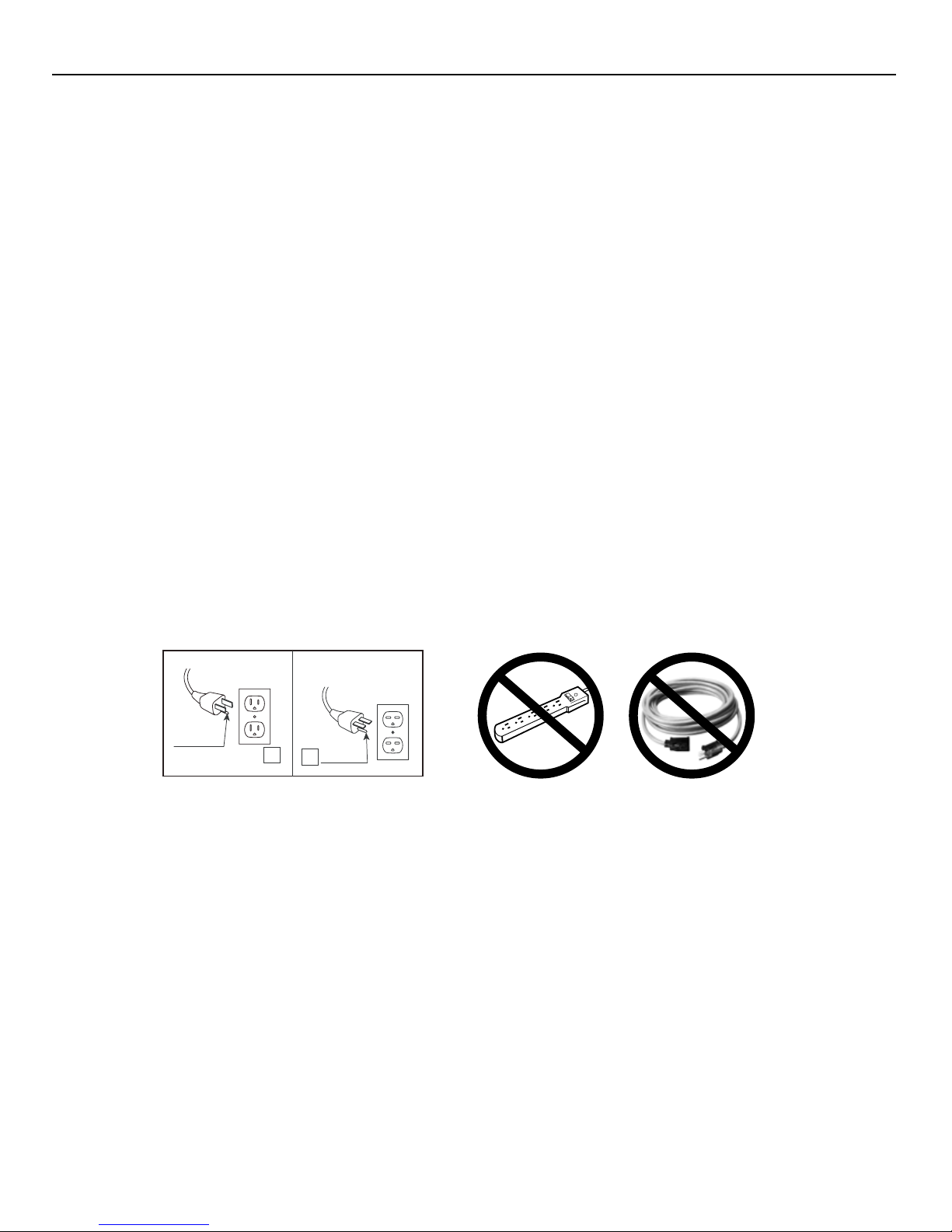
12. Connect to properly grounded outlets only. This heater is for use on 120 volts. The cord has a plug as shown at A in Fig.1 Do not
use a 2 prong adapters. Never use with an extension cord or relocatable power tap (outlet/power strip).
A
B
13. This appliance, when installed, must be electrically grounded in accordance with local codes or, in the absence of local codes, with
the current CSA C22.1 Canadian Electrical Code or for U.S.A. installations, follow local codes and the National Electrical Code,
ANSI/NFPA NO.70.
14. Do not insert or allow foreign objects to enter any ventilation or exhaust opening as this may cause an electric shock or re, or
damage the appliance.
15. To prevent a possible re, do not block air intakes or exhaust in any manner. Do not use on soft surfaces, like a bed, where opening
may become blocked.
16. This appliance has hot and arcing or sparking parts inside. Do not use it in areas where gasoline, paint or ammable liquids are
used or stored. This replace should not be used as a drying rack for clothing. Christmas stockings or decorations should not be
hung in the area of it.
Fig.1
17. Use this appliance only as described in the manual. Any other use not recommended by the manufacturer may cause re, electric
shock or injury to persons.
18. This heater may include an visual alarm to warn that parts of the heater are getting excessively hot. If the alarm illuminates,
immediately turn the heater off and inspect for any objects on or adjacent to the heater that may have blocked the airow or
otherwise caused high temperatures to have occurred. DO NOT OPERATE THE HEATER WITH THE ALARM ILLUMINATING.
SAVE THESE INSTRUCTIONS
A353
3
www.tsicustomerservice.com
Page 4

Warranty
Warranty
The manufacturer warrants this product to be free from manufacturing and material defects for a period of one year from date of
purchase, subject to the following conditions and limitations:
1. Install and operate this Electric Fireplace in accordance with the installation and operating instructions furnished with the product
at all times. Any unauthorized repair, alteration, willful abuse, accident, or misuse of the product shall nullify this warranty.
2. This warranty is non-transferable and is made to the original owner, provided that the purchase was made through an authorized
supplier of the product.
3. The warranty is limited to the repair or replacement of part(s) found to be defective in material or workmanship, provided that
such part(s) have been subjected to normal conditions of use and service, after said defect is conrmed by the manufacturer’s
inspection.
4. The manufacturer may, at its discretion, fully discharge all obligations with respect to this warranty by refunding the wholesale
price of the defective part(s).
5. Any installation, labor, construction, transportation, or other related costs/expenses arising from defective part(s), repair,
replacement, or otherwise of same, will not be covered by this warranty, nor shall the manufacturer assume responsibility
for same.
6. The owner/user assumes all other risks, if any, including the risk of any direct, indirect or consequential loss or damage arising out
of the use, or inability to use the product, except as provided by law.
7. All other warranties – expressed or implied – with respect to the product, its components and accessories, or any obligations/
liabilities on the part of the manufacturer are hereby expressly excluded.
8. The manufacturer neither assumes, nor authorizes any third party to assume on its behalf, any other liabilities with respect to
the sale of the product.
9. The warranties as outlined within this document do not apply to non accessories used in conjunction with the installation of
this product.
10. This warranty gives you specic legal rights, and you may also have other rights which vary from state to state.
This warranty is void if:
a. The replace is subjected to prolonged periods of dampness or condensation.
b. There has been unauthorized alteration, willful abuse, accident, or misuse of the product.
c. You do not have the original receipt of purchase.
Customer Service
www.tsicustomerservice.com
For Customer Service Call 1-888-674-7517
Questions? Our message centers are available 7 days a week 24 hours a day at our toll-free help line. Our
Consumer Service department is available Monday – Friday 8:30 am – 5:30 pm EST. We can help you with
assembly and if necessary, replace damaged/missing parts.
IMPORTANT:
Before contacting Customer Service please have this information available:
•SerialNumber
•ModelNumber
•SalesReceiptorProofofPurchase
A353
4
www.tsicustomerservice.com
Page 5
Pre-Operation
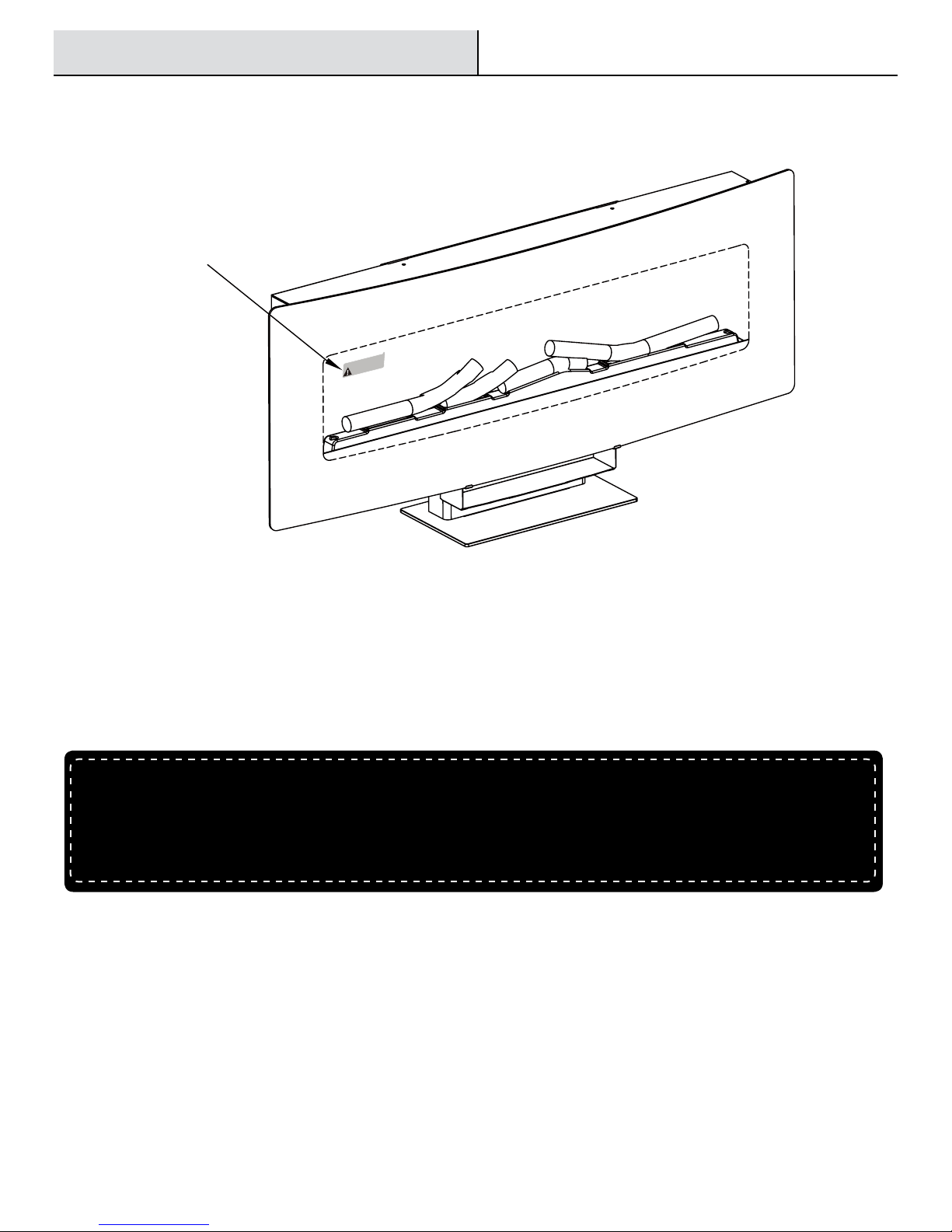
1. Remove the product identication sticker from the front of the replace.
Product
Identication
Sticker
Model / Modèle / Modelo: 48HF201CGT
SN #: AB-12345-A
Keep this number for service!
Gardez ce numéro pour le service!
Mantega este número para servicio!
2. Attach the Product Identication Sticker to this Manual below for future reference. This information is used for product registration and
also is necessary for customer service.
Attach Product Identication Sticker Here
3. Go to www.tsicustomerservice.com for product warranty registration. If you are unable to complete registration save your proof of
purchase for warranty purposes.
A353
5
www.tsicustomerservice.com
Page 6
Pre-Assembly
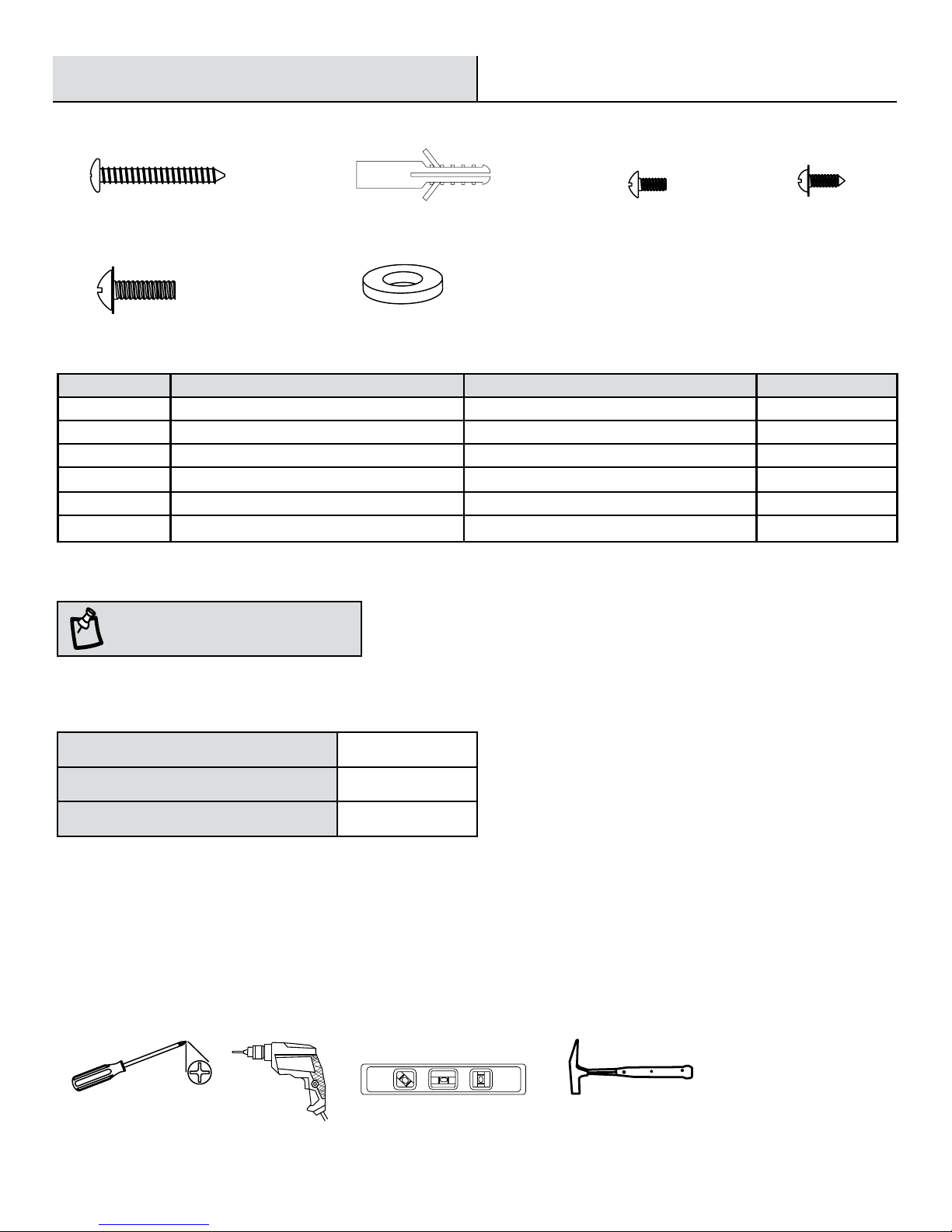
HARDWARE INCLUDED
AA
EE
Part Description Part Number Quantity
AA Anchor Screw 36II200-AA 6
BB Wall Anchor 36II200-BB 6
CC Screw 4mm x 8mm (2 Pre-Attached) 36II200-CC 11
DD Screw 4mm x 6mm 36II200-DD 2
EE Screw 6mm x 14mm 36II200-EE 6
FF Washer 36II200-FF 4
NOTE:
Hardware not shown to actual size.
BB
FF
CC
DD
PRODUCT SPECIFICATIONS
Voltage 120 VAC, 60 Hz
Amps 12.5 Amps
Watts 1500 Watts
PLANNING ASSEMBLY
Before beginning assembly of product, make sure all parts are present. Compare parts with Hardware Included and Package Contents lists.
If any part is missing or damaged, do not attempt to assemble, install or operate the product. Contact customer service for replacement
parts.
Estimated Assembly Time: 60 Minutes
Tools Required for Assembly (not included): Phillips screwdriver, Drill, Hammer, Level
Phillips Screwdriver
LevelDrill Hammer
A353
6
www.tsicustomerservice.com
Page 7
Pre-Assembly (continued)
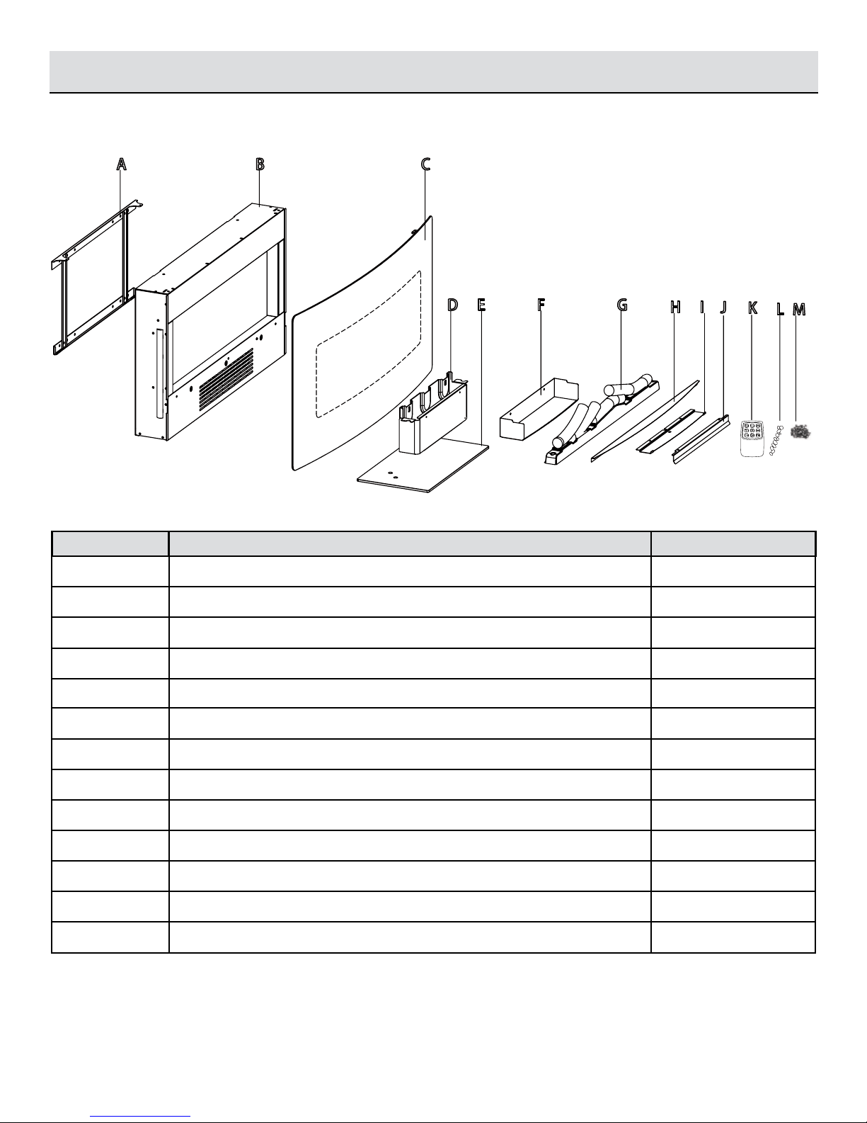
PACKAGE CONTENTS
A
Part Description Quantity
A Mounting Bracket (Pre-Attached) 1
B
C
D E G
F
H I
J
K
L
M
B Fireplace 1
C Front Frame 1
D Base Bracket 1
E Base 1
F Lower Air Outlet Bafe 1
G Logset 1
H Glass Bafe 1
I Upper Air Outlet Bafe 1
J Back Air Outlet Bafe 1
K Remote Control 1
L Decorative Rocks Varies
M Fireglass Varies
A353
7
www.tsicustomerservice.com
Page 8

Installation Options
Operation
The replace can be installed with 2 options:
1. Hanging on a wall with provided mounting bracket.
2. Freestanding using the pedestal base.
Follow installation instructions below based on installation preference.
Option 1
Wall Hanging....page 9
Option 2
Pedestal Base....page 13
A353
8
www.tsicustomerservice.com
Page 9

Installation - Wall Mounting
Operation
Hanging on a wall
Your new electric replace may be installed virtually anywhere in your home. However, when choosing a location be sure to follow the
general instructions included. For best results install out of direct sunlight. Power supply service must be either completed or placed within
the electric replace prior to nishing to avoid reconstruction.
Min. 5 cm
2 in.
Min. 5 cm
2 in.
Min. 60 cm
24 in.
WARNING:
from the front and sides of the electric replace.
Clearance to combustibles
Sides 2 in. / 5 cm
Floor 24 in. / 60 cm
Top 2 in. / 5 cm
Back 0 in. / 0 cm
Keep drapery and other furnishings at least 3 ft / 1 m
A353
9
www.tsicustomerservice.com
Page 10

B
CC
A
Installation - Wall Mounting
Operation
1
Removing the Mounting Bracket
Remove the Mounting Bracket (A) from the back of the
Fireplace (B) by removing the two pre-attached Screws
(CC) at the top back of the unit.
2
Floor
Choosing a Wall Location
Choose a wall location to attach the Mounting
Bracket (A). Position the Mounting Bracket (A)
in the desired location.
Use a level to align the bracket and mark the four holes
with a pencil.
A
3
A353
Drilling the Holes
Drill six 7/25 in. (7 mm) holes in the wall.
Insert the Wall Anchors (BB) into the holes using
a hammer.
BB
10
www.tsicustomerservice.com
Page 11

Installation - Wall Mounting (continued)
B
B
CC
I
CC
J
Operation
Operation
4
Attaching the Mounting Bracket
Attach the Mounting Bracket (A) to the wall by fastening
the six Anchor Screws (AA) into the wall anchors.
A
AA
5
Attaching Lower Air Outlet Bafe
Attach Glass Bafe (H) to the replace by fastening the
Screws (CC).
H
CC
Attaching the Upper and back Air
6
Outlet Bafe
Attach the upper air outlet(I) and back air outlet(J) to the
replace by fastening the screw (CC).
7
Hanging the Fireplace
Hang the Fireplace (B) on the hooks at the bottom of
the Mounting Bracket (A) and push the Fireplace (B)
into the Mounting Bracket (A).
Re-fasten the two screws removed in Step 1.
A353
11
www.tsicustomerservice.com
Page 12

B
C
Installation - Wall Mounting (continued)
Operation Operation
8
Hanging the Front Frame
Mount the Front Frame (C) to the Fireplace (B) using the mounting hooks to hang the front frame.
Mounting
Hooks
Mounting Hooks
9
A353
Securing the Front Frame
Secure the top frame hooks with the two retaining
Screws (DD).
Continue to the fuel bed setup instructions (Page 18).
12
DD
www.tsicustomerservice.com
Page 13

Installation - Pedestal Base
E
B
I
CC
Operation
1
Fastening the Base Bracket
Use two Screws (CC) to fasten the lower Air Outlet Bafe
(F) to the Base Bracket (D).
D
F
CC
2
Attaching the Small Base Bracket
Use four Screws (EE) and four Washers (FF) to fasten the
Base (E) to the Base Bracket (D).
E
FF
EE
3
Attaching Lower Air Outlet Bafe
Attach Glass Bafe (H) to the replace by fastening the
Screws (CC).
B
H
CC
4
Attaching the Upper Air Outlet Bafe
Attach the upper air outlet(I) to the replace by
fastening the screw (CC).
A353
13
www.tsicustomerservice.com
Page 14

Installation - Pedestal Base
D
B
EE
Operation
5
6
Attaching the Base Bracket
Fasten the Base Bracket (D) to the Fireplace (B) with the
provided Screws (EE).
Securing the Top Frame
Mount the Front Frame (C) to the Fireplace (B) using the mounting hooks to hang the front frame.
C
Mounting
Hooks
B
Tighten the two Screws (DD).
Continue to the fuel bed setup instructions (Page 15).
A353
Mounting Hooks
DD
14
www.tsicustomerservice.com
Page 15

Fuel Bed Setup Instructions
Operation
1
Removing the Logset
The replace has the option of either using the pre-installed logset or the included transparent tray assembly. To
change the logset to the tray remove the emberbed with logset.
2
A353
Placing the Fireglass/ Rocks
Place the Fireglass (M) or the Rocks (L) as desired.
15
www.tsicustomerservice.com
Page 16

Operation
Operation
Control Panel
The replace can be operated by either the remote control or the control panel.
A353
16
www.tsicustomerservice.com
Page 17

Operation (continued)
Operation
FUNCTION
HEATER
TIMER
FLAME COLOR
ICON
/▲ ▼
DESCRIPTION
To set the thermostat use the Heater button on the control panel to select
the desired temperature.
The thermostat setting range is 62 °F - 82 °F or 17 °C - 27 °C or continously
ON and OFF (00).
The thermostat is adjustable by 2°F or 1°C increments by pressing the Up
or Down “▲ ▼ “ buttons on the remote control.
To change between °F and °C press and hold the HEATER button on the
control panel for 3 seconds.
Press the Timer button to cycle through the ten timer settings (30
minutes, 1 Hour, 2H, 3H, 4H, 5H, 6H, 7H, 8H and 9H) and the OFF (00)
setting.
There are 5 unique Spectrare™ ame effects that can be selected.
1: Spectrare™
2: Sapphire
3: Amethyst
4: Campre
5: Midnight Fire
FLAME INTENSITY
FLAME SPEED
UPLIGHTS
SIDELIGHTS
AU: Auto Cycle which will automatically fade in and fade out a new color
ame effect periodically.
00: OFF
The intensity is only adjustable from the remote control.
Each ame color option has 5 intensity options available.
The ame speed is only adjustable from the remote control.
Each ame color option has speed options available.
Setting 1 is slowest ranging up to setting 5 which is the fastest.
Press the Uplights button on the remote control to change the uplight
between the ve settings: white, blue, white/blue, auto-cycling and OFF(00).
Press the Sidelights button on the remote control to change the sidelight
between the ve settings: amber, blue, blue/amber, auto-cycling and OFF
(0).
A353
17
www.tsicustomerservice.com
Page 18

Operation (continued)
Operation
Replacing the Remote Control Battery Disposing of Used Batteries
7 8
When the remote control stops operating or its range
seems reduced, it is time to replace the battery with
new ones.
On the back end of the remote, press and slide
the battery door open and remove the old batteries.
Insert two AAA batteries, checking that the + and -
sides of the battery match inside the battery
compartment.
Replace the battery compartment door.
NOTE:
Do not mix old and new batteries. Do not mix
alkaline, standard (carbonzinc), or rechargeable (nicad,
nimh, etc) batteries.
NOTE:
measured pace. Press the remote control buttons with
an even motion and gentle pressure. Repeatedly pressing
buttons in rapid succession may cause the transmitter to
malfunction.
Please operate the remote control at a slow
Do not ingest batteries.
The battery may contain hazardous substances that
could endanger the enviroment and human health.
This symbol marked on the battery and/or packaging
indicates that used battery shall not be treated as
municipal waste. Instead it should be left at the
appropriate collection point for recycling.
By correctly disposing used batteries, you prevent
potential negative consequences for the environment
and human health. Recycling used materials also
conserves natural resources.
For more information about collecting and recycling
used batteries, please contact your local municipality,
your waste disposal service or the point of sale where
you purchased this product.
NOTE:
Batteries should be removed if the product is
to be left unused for a long time.
· For best results, use 2pcs AAA alkaline batteries.
· Install only new batteries of the same type in your product.
· Failure to insert batteries in the correct polarity, as indicated in the battery compartment, may shorten the life of the
batteries or cause batteries to leak.
· Do not mix old and new batteries.
· Do not mix Alkaline, Standard (Carbon-Zinc) or Rechargeable (Nickel Cadmium) or (Nickel Metal Hydride) batteries.
· Danger of explosion if battery is incorrectly replaced.
· Do not ingest batteries.
Batteries should be recycled or disposed of as per state and local guidelines.
A353
18
www.tsicustomerservice.com
Page 19

FCC/IC Information
Warning: Changes or modications to this unit not expressly approved by the party responsible for compliance could void user’s authority
to operate the equipment.
NOTE: This equipment has been tested and found to comply with the limits for Class B digital device, pursuant to part 15 of the FCC Rules.
These limits are designed to provide reasonable protection against harmful interference in a residential installation. This equipment
generates, uses, and can radiate radio frequency energy and, if not installed and used in accordance with the instructions, may cause
harmful interference to radio communications. However, there is no guarantee that interference will not occur in a particular installation.
If this equipment does cause harmful interference to radio or television reception, which can be determined by turning the equipment off
and on, the user is encouraged to try to correct the interference by one or more of the following measures:
Reorient or relocate the receiving antenna.
Increase the separation between the equipment and the receiver.
Connect the equipment into an outlet on a circuit different from that to which the receiver is connected.
Consult the dealer or an experienced radio/TV technician for help.
This device complies with Part 15 of the FCC Rules. Operation is subject to the following two conditions:
(1) This device may not cause harmful interference, and
(2) this device must accept any interference received, including interference that may cause undesired operation.
This Class B digital apparatus complies with Canadian ICES-003.
Care and Cleaning
Clean the metal trim using a soft cloth, slightly dampened with a citrus oil-based product and buff with a soft, clean cloth. DO NOT use
brass polish or household cleaners as these products will damage the metal trim.
Purchase citrus oil-based products at a hardware store.
WARNING:
carried out by a licensed electrician in accordance with national and local codes. If repairing or replacing any electrical component or wiring,
the original wire routing, color coding and securing locations must be followed. During any service of this appliance, the power to the unit
must be turned off. First turn the main power switch to the OFF position. Then remove the electrical plug from the wall outlet.
WARNING:
the sides.
WARNING:
electrical shock and injury to persons.
WARNING:
replace and replace any part of the electrical system.
Make sure the power is turned off before proceeding with repairs. Any electrical repairs or rewiring of this unit should be
Keep electrical cords, drapery, furniture and other combustibles at least 3 ft (0.9 m) from the front of the heater and away from
Electrical outlet wiring must comply with local building codes and other applicable regulations to reduce the risk of fire,
Do not use this replace if any part of it has been under water. Immediately call a qualied service technician to inspect the
WARNING:
A353
Disconnect power before attempting any maintenance or cleaning to reduce the risk of re, electrical shock or personal injury.
19
www.tsicustomerservice.com
Page 20

Troubleshooting
PROBLEM POSSIBLE CAUSE CORRECTIVE ACTION
Display shows “ ”. The thermostat sensor is broken
or disconnected.
Unplug the replace, remove the back panel of the replace and check
that the thermostat is plugged into the main circuit board. If this does not
solve the problem contact customer service for a replacement thermostat
sensor.
Display shows “ ”.
Display shows “ ”.
The heater does not blow warm
air.
There is no power. There is no power to the unit.
The heater does not blow any
air.
The heater does not work, but
Power and Heater settings are
“ON” and thermostat is set.
Flame effect works but heater
function does not, and the ame
effect ashes when the Heater
button is pressed.
The thermostat sensor is
broken.
Manual Reset overheat
protection has triggered.
The heater is in a cool down
cycle.
Thermostat setting is preventing
heater from turning on.
Manual reset overheat
protection triggered.
The heater is disabled.
Contact customer service for a replacement thermostat sensor.
Inspect the heater and check that the air inlets and outlets are not blocked
as this may cause overheating. Unplug the heater for 30 minutes and allow
it to cool down. Replug, operate, and monitor the heater for signs of
overheating. If the problem persists discontinue use of the heater and
contact customer service.
This is normal operation and the heater will continue to run for several
minutes before shutting down. Times will vary based on temperatures.
During this time cool air will blow.
Check that unit is plugged into a standard 120V outlet. Press the Power
button several times and make sure the power is set to the “ON” position.
Adjust the temperature settings to ensure that the thermostat is set higher
than the current room temperature.
Turn the Power to “OFF” and unplug the unit from the wall outlet for 30
minutes. After 30 minutes plug the unit back into wall outlet, and operate
as normal. If the problem persists contact customer service.
With the power on press and hold the Power button on the control panel
for 10 seconds. Once re-enabled the ame effect will ash multiple times.
The remote control is not
working.
The noise when the heater is on
is louder than normal.
Abnormal noise when the heater
is not on and the ame effect
is on.
Change the remote batteries.
There are no batteries or the
signal is poor.
a. The air intakes are dirty or
obstructed.
b. The blower/heater assembly
is defective.
The spinner motor is defective. Contact Customer Service for a new Spinner Motor.
Operate remote transmitter at a slow measured pace.
Press the remote control buttons with an even motion
and gentle pressure. Repeatedly pressing buttons in rapid
succession may cause the transmitter to malfunction.
a. Check the air intakes for obstructions or high dust build up.
b. Contact Customer Service for a new Heater/Blower Assembly.
A353
20
www.tsicustomerservice.com
Page 21

Replacement Parts
A
C
D
E
N
O
G
I
J
K
L
P
Q
B
F
M
H
Part Description Part Number Qty.
A Remote Control 9 Buttons P127 1
B BASE and STAND assembly Y15-S162-BS 1
C Flame Generator Drive Motor P10-6 1
D Control Panel Circuit Board Y15-S162-P32 1
E Right backlight PCBA Y15-S162-P49R 1
F Clear Tray 48HF201-H 1
G Logsets 48HF201-F 1
H Emberbed Circuit Board Y15-S162-P44E 3
I Flame Circuit Board Y15-S162-P40 3
J Blue backlight PCBA Y15-S162-P40BL 3
K Main Circuit Board Y15-S162-P15 1
L LCD Display Y15-S158-P79 1
M Bracket Mounting Y15-S162-MT 1
N Left backlight PCBA Y15-S162-P49L 1
O Heat/Blower Elements Y15-S162-P01 1
P Fire glass Y15-S162-FG varies
Q Rocks Y15-S162-RK varies
A353
21
www.tsicustomerservice.com
Page 22

www.tsicustomerservice.com
A353
22
www.tsicustomerservice.com
 Loading...