

Duracell Inverter 1500 Owner's Manual
Owner's Guide
975-0350-01-01 REV. B Printed in China
t 1 408 987 6359
www.xantrex.com/support
ARTWORK NO. 975-0350-01-01 REV. B

Owner’s Guide

About Xantrex
Xantrex Technology Inc. is a world-leading supplier of advanced power electronics and controls with
products from 50 watt mobile units to 1 MW utility-scale systems for wind, solar, batteries, fuel cells,
microturbines, and backup power applications in both grid-connected and stand-alone systems. Xantrex
products include inverters, battery chargers, programmable power supplies, and variable speed drives
that convert, supply, control, clean, and distribute electrical power.
Trademarks
DURACELL® is a registered trademark of The Gillette Company, used under license. All rights
reserved.
XANTREX is a registered trademark of Xantrex International.
Other trademarks, registered trademarks, and product names are the property of their respective owners
and are used herein for identification purposes only.
Notice of Copyright
Duracell® Inverter 1500 Owner’s Guide © 2007 Duracell. All rights reserved.
Exclusion for Documentation
UNLESS SPECIFICALL Y AGREED TO IN WRITING, XANTREX TECHNOLOGY INC. (“XANTREX”)
(a) MAKES NO WARRANTY AS TO THE ACCURACY, SUFFICIENCY OR SUITABILITY OF ANY TECHNICAL OR
OTHER INFORMATION PROVIDED IN ITS MANUALS OR OTHER DOCUMENTATION.
(b) ASSUMES NO RESPONSIBILITY OR LIABILITY FOR LOSSES, DAMAGES, COSTS OR EXPENSES, WHETHER
SPECIAL, DIRECT, INDIRECT, CONSEQUENTIAL OR INCIDENTAL, WHICH MIGHT ARISE OUT OF THE USE OF
SUCH INFORMATION. THE USE OF ANY SUCH INFORMATION WILL BE ENTIRELY AT THE USER’S RISK.
(c) REMINDS YOU THAT IF THIS MAN UAL IS IN ANY LANGUAGE OTHER THAN ENGLISH, ALTHOUGH STEPS
HAVE BEEN TAKEN TO MAINTAIN THE ACCURACY OF THE TRANSLA TION, THE ACCURACY CANNOT BE
GUARANTEED. APPROVED XANTREX CONTENT IS CONTAINED WITH THE ENGLISH LANGUAGE VERSION
WHICH IS POSTED AT www.xantrex.com.
Date and Revision
Aug 2007 Revision B
Pa rt Number
975-0350-01-01
Product Number
813-1500-07
Contact Information
Phone: 1 408 987 6359
Website: www.xantrex.com/support

About This Guide
Purpose
The purpose of this Owner’s Guide is to provide explanations and
procedures for installing, operating, maintaining, and troubleshooting the
Duracell® Inverter 1500.
Scope
The Guide provides safety guidelines, detailed planning and setup
information, procedures for installing the inverter, as well as information
about operating and troubleshooting the unit. It does not provide details
about particular brands of batteries. You need to consult individual battery
manufacturers for this information.
Audience
The Guide is intended for anyone who needs to install and operate the
Duracell® Inverter 1500.
iii

About This Guide
Conventions Used
The following conventions are used in this guide.
WARNING
Warnings identify conditions that could result in personal injury or loss of life
CAUTION
Cautions identify conditions or practices that could result in damage to the unit or
other equipment.
Important:
but not as serious as a caution or warning.
Related Information
You can find more information about Xantrex Technology Inc. as well as
its products and services at www.xantrex.com
These notes describe things that are important for you to know,
iv 975-0350-01-01

Important Safety Instructions
WARNING
This chapter contains important safety and operating instructions. Read and keep
this Owner’s Guide for future reference.
1. Before installing and using the Duracell® Inverter 1500, read all
instructions and cautionary markings on the Duracell® 1500, the
batteries, and all appropriate sections of this guide.
2. Do not expose the Duracell® 1500 to rain, snow, spray, or bilge
water. To reduce risk of fire hazard, do not cover or obstruct the
ventilation openings. Do not install the Duracell® 1500 in a zeroclearance compartment. Overheating may result.
3. Use only attachments recommended or sold by the manufacturer.
Doing otherwise may result in a risk of fire, electric shock, or injury
to persons.
4. To a void a risk of fire and electric shock, make sure that existing
wiring is in good condition and that wire is not undersized. Do not
operate the Duracell® 1500 with damaged or substandard wiring.
5. Do not operate the Duracell® 1500 if it has received a sharp blow,
been dropped, or otherwise damaged in any way. If the Duracell®
1500 is damaged, see the Warranty section.
6. Do not disassemble the Duracell® 1500. It contains no userserviceable parts. See Warranty for instructions on obtaining service.
Attempting to service the Duracell® 1500 yourself may result in a
risk of electrical shock or fire. Internal capacitors remain charged
after all power is disconnected.
7. To re duce the risk of electrical shock, disconnect both AC and DC
power from the Duracell® 1500 before attempting any maintenance
or cleaning or working on any circuits connected to the Duracell®
1500. Turning off controls will not reduce this risk.
8. The Duracell® 1500 must be provided with an equipment-g r ounding
conductor connected to the AC input ground.
v

Safety
Explosive Gas Precautions
WARNING: Explosion hazard
1. Working in the vicinity of lead-acid batteries is dangerous. Batteries
generate explosive gases during normal operation . Therefore, you
must read this guide and follow the instructions exactly before
installing or using your Duracell® 1500.
2. This equipment contains components which tend to produce arcs or
sparks. T o prevent fire or explosion, do not install the Duracell® 1500
in compartments containing batteries or flammable materials, or in
locations that require ignition-protected equipment. This includes any
space containing gasoline-powered machinery, fuel tanks, as well as
joints, fittings, or other connections between components of the fuel
system.
3. To reduce the risk of battery explosion, follow these instructions and
those published by the battery manufacturer and the manufacturer of
the equipment in which the battery is installed.
vi 975-0350-01-01

Precautions When Working With Batteries
WARNING: Explosion or fire hazard
1. Follow all instructions published by the battery manufacturer and the
manufacturer of the equipment in which the battery is installed.
2. Make sure the area around the battery is well ventilated.
3. Never smoke or allow a spark or flame near the engine or batteries.
4. Use caution to reduce the risk or dropping a metal tool on the battery.
It could spark or short circuit the battery or other electrical parts and
could cause an explosion.
5. Remove all metal items, like rings, bracelets, and watches when
working with lead-acid batteries. Lead-acid batteries produce a short
circuit current high enough to weld metal to skin, causing a severe
burn.
Safety
6. Have someone within range of your voice or close eno ugh to come to
your aid when you work near a lead-acid battery.
7. Have plenty of fresh water and soap nearby in case battery acid
contacts skin, clothing, or eyes.
8. Wear complete eye protection and clothing protection. Avoid
touching your eyes while working near batteries.
9. If battery acid contacts skin or clothing, wash immediately with soap
and water. If acid enters your eye, immediately flood it with running
cold water for at least twenty minutes and get medical attention
immediately.
10. If you need to remove a battery, always remove the ground terminal
from the battery first. Make sure all accessories are off so you don’t
cause a spark.
975-0350-01-01 vii

Safety
Precautions for Using Rechargeable Appliances
CAUTION: Equipment damage
The output of the inverter is non-sinusoidal.
Most rechargeable battery-operated equipment uses a separate charger or
transformer that is plugged into an AC receptacle and produces a low
voltage charging output.
Some chargers for small rechargeable batteries can be damaged if
connected to the Duracell® 1500. Do not use the following with the
Duracell® Inverter 1500:
• Small battery-operated appliances like flashlights, razors, and night
lights that can be plugged directly into an AC receptacle to recharge.
• Some chargers for battery packs used in power hand tools. These
affected chargers display a warning label stating that dangerous
voltages are present at the battery terminals.
If you are unsure about using your rechargeable appliance with the
Duracell® 1500, contact the equipment manufacturer to determine the
rechargeable appliance’s compatibility with the modified sinewave (nonsinusoidal) AC waveform.
CAUTION: Equipment damage
Do not connect live AC power to the XPower inverter’s AC outlets. The inverter
will be damaged even if it is switched OFF.
Do not connect any AC load that has its neutral conductor connected to ground to
the XPower inverter.
viii 975-0350-01-01

Contents
Important Safety Instructions
1
Introduction
Quality Power - - - - - - - - - - - - - - - - - - - - - - - - - - - - - - - - - - - - - - - - - - - - - - - - 1–1
Ease of Use - - - - - - - - - - - - - - - - - - - - - - - - - - - - - - - - - - - - - - - - - - - - - - - - - -1–2
Comprehensive Protection - - - - - - - - - - - - - - - - - - - - - - - - - - - - - - - - - - - - - - - - 1–2
2
Features
Materials List- - - - - - - - - - - - - - - - - - - - - - - - - - - - - - - - - - - - - - - - - - - - - - - - - 2–1
AC Panel- - - - - - - - - - - - - - - - - - - - - - - - - - - - - - - - - - - - - - - - - - - - - - - - - - - -2–2
DC Panel- - - - - - - - - - - - - - - - - - - - - - - - - - - - - - - - - - - - - - - - - - - - - - - - - - - -2–3
3
Installation
Designing Your Installation - - - - - - - - - - - - - - - - - - - - - - - - - - - - - - - - - - - - - - - 3–1
Installation Codes - - - - - - - - - - - - - - - - - - - - - - - - - - - - - - - - - - - - - - - - - - - 3–4
Calculating Battery Requirements - - - - - - - - - - - - - - - - - - - - - - - - - - - - - - - -3–4
Choosing an Effective Charging System - - - - - - - - - - - - - - - - - - - - - - - - - - - 3–4
Choosing an Appropriate Location - - - - - - - - - - - - - - - - - - - - - - - - - - - - - - -3–5
Calculating Cable Sizes - - - - - - - - - - - - - - - - - - - - - - - - - - - - - - - - - - - - - - - 3–6
Calculating Size of DC Input Cables - - - - - - - - - - - - - - - - - - - - - - - - - - - 3–6
Calculating Size of Chassis Ground Cable - - - - - - - - - - - - - - - - - - - - - - - 3–7
Calculating Fuse/Circuit Breaker Size - - - - - - - - - - - - - - - - - - - - - - - - - - - - - 3–8
- - - - - - - - - - - - - - - - - - - - - - - - - - - - - - - - - - -v
Installing the Duracell® 1500- - - - - - - - - - - - - - - - - - - - - - - - - - - - - - - - - - - - - - 3–9
Safety Instructions - - - - - - - - - - - - - - - - - - - - - - - - - - - - - - - - - - - - - - - - - - 3–9
Installation Tools and Materials - - - - - - - - - - - - - - - - - - - - - - - - - - - - - - - - -3–9
Overview of Installation Steps - - - - - - - - - - - - - - - - - - - - - - - - - - - - - - - - - 3–11
Mounting the Inverter - - - - - - - - - - - - - - - - - - - - - - - - - - - - - - - - - - - - - - - 3–11
Connecting the Chassis Ground - - - - - - - - - - - - - - - - - - - - - - - - - - - - - - - - 3–12
Grounding Locations - - - - - - - - - - - - - - - - - - - - - - - - - - - - - - - - - - - - - 3–12
Chassis Ground Screw - - - - - - - - - - - - - - - - - - - - - - - - - - - - - - - - - - - - 3–13
Connecting the DC Cables - - - - - - - - - - - - - - - - - - - - - - - - - - - - - - - - - - - - 3–13
975-0350-01-01 ix

Contents
4
Operation
Turning the Inverter On and Off - - - - - - - - - - - - - - - - - - - - - - - - - - - - - - - - - - - - 4–1
Operating Several Loads at Once - - - - - - - - - - - - - - - - - - - - - - - - - - - - - - - - - - - 4–2
Turning the Inverter Off Between Uses - - - - - - - - - - - - - - - - - - - - - - - - - - - - - - - 4–2
Operating Limits - - - - - - - - - - - - - - - - - - - - - - - - - - - - - - - - - - - - - - - - - - - - - - 4–3
Power Output - - - - - - - - - - - - - - - - - - - - - - - - - - - - - - - - - - - - - - - - - - - - - 4–3
Input Voltage - - - - - - - - - - - - - - - - - - - - - - - - - - - - - - - - - - - - - - - - - - - - - 4–3
Inverter Loads - - - - - - - - - - - - - - - - - - - - - - - - - - - - - - - - - - - - - - - - - - - - - - - - 4–4
High Surge Loads - - - - - - - - - - - - - - - - - - - - - - - - - - - - - - - - - - - - - - - - - - 4–4
Trouble Loads - - - - - - - - - - - - - - - - - - - - - - - - - - - - - - - - - - - - - - - - - - - - - 4–4
Routine Maintenance - - - - - - - - - - - - - - - - - - - - - - - - - - - - - - - - - - - - - - - - - - - 4–5
Duracell® 1500 unit - - - - - - - - - - - - - - - - - - - - - - - - - - - - - - - - - - - - - - - - - 4–5
Batteries - - - - - - - - - - - - - - - - - - - - - - - - - - - - - - - - - - - - - - - - - - - - - - - - - 4–5
Recycling - - - - - - - - - - - - - - - - - - - - - - - - - - - - - - - - - - - - - - - - - - - - - - - - - - - 4–5
5
Troubleshooting
Common Problems- - - - - - - - - - - - - - - - - - - - - - - - - - - - - - - - - - - - - - - - - - - - - 5–2
Buzz in Audio Equipment - - - - - - - - - - - - - - - - - - - - - - - - - - - - - - - - - - - - - 5–2
Television Reception - - - - - - - - - - - - - - - - - - - - - - - - - - - - - - - - - - - - - - - - 5–2
Troubleshooting Reference - - - - - - - - - - - - - - - - - - - - - - - - - - - - - - - - - - - - - - - 5–3
A
Specifications
Electrical Performance - - - - - - - - - - - - - - - - - - - - - - - - - - - - - - - - - - - - - - - - - -A–1
Physical Specifications - - - - - - - - - - - - - - - - - - - - - - - - - - - - - - - - - - - - - - - - - -A–1
Dimensions for Mounting - - - - - - - - - - - - - - - - - - - - - - - - - - - - - - - - - - - - - - - -A–2
B
Battery Types
Battery Types - - - - - - - - - - - - - - - - - - - - - - - - - - - - - - - - - - - - - - - - - - - - - - - -B–1
Automotive Starting Batteries - - - - - - - - - - - - - - - - - - - - - - - - - - - - - - - - - -B–1
Deep-Cycle Batteries - - - - - - - - - - - - - - - - - - - - - - - - - - - - - - - - - - - - - - - -B–2
Battery Size- - - - - - - - - - - - - - - - - - - - - - - - - - - - - - - - - - - - - - - - - - - - - - - - - -B–2
Estimating Battery Requirements - - - - - - - - - - - - - - - - - - - - - - - - - - - - - - - - - - -B–4
Battery Sizing Example - - - - - - - - - - - - - - - - - - - - - - - - - - - - - - - - - - - - - -B–4
Battery Sizing Worksheet - - - - - - - - - - - - - - - - - - - - - - - - - - - - - - - - - - - - -B–5
x 975-0350-01-01

Using Multiple Batteries - - - - - - - - - - - - - - - - - - - - - - - - - - - - - - - - - - - - - - - - -B–6
Two Batteries Connected In Parallel - - - - - - - - - - - - - - - - - - - - - - - - - - - - - -B–6
Two Separate Battery Banks - - - - - - - - - - - - - - - - - - - - - - - - - - - - - - - - - - -B–6
Battery Tips- - - - - - - - - - - - - - - - - - - - - - - - - - - - - - - - - - - - - - - - - - - - - - - - - -B–7
C
Alternators and Charging Systems
Charging System Requirements - - - - - - - - - - - - - - - - - - - - - - - - - - - - - - - - - - - -C–1
Charging With an Engine Alternator - - - - - - - - - - - - - - - - - - - - - - - - - - - - - - - - -C–2
Using a Standard Vehicle Alternator - - - - - - - - - - - - - - - - - - - - - - - - - - - - - -C–2
Using an Alternator Controller - - - - - - - - - - - - - - - - - - - - - - - - - - - - - - - - - -C–2
Using a High-Output Alternator - - - - - - - - - - - - - - - - - - - - - - - - - - - - - - - - -C–2
Charging From AC Power - - - - - - - - - - - - - - - - - - - - - - - - - - - - - - - - - - - - - - - -C–3
Charging From Alternative Energy Sources - - - - - - - - - - - - - - - - - - - - - - - - - - - -C–3
Contents
Warranty and Return Information
Direct to place of purchase - - - - - - - - - - - - - - - - - - - - - - - - - - - - - - - -WA–4
Direct to Xantrex - - - - - - - - - - - - - - - - - - - - - - - - - - - - - - - - - - - - - - WA–4
- - - - - - - - - - - - - - - - - - - - - - - - - - -WA–1
975-0350-01-01 xi

xii

1 Introduction
Congratulations on your purchase of the Duracell® Inverter 1500! The
Duracell® 1500 has been designed to give you quality power, ease of use,
and reliability.
Please take a few moments to read this chapter to familiarize yourself
with the main performance features and protection features of the
Duracell® 1500.
Quality Power
The Duracell® 1500 is a quality inverter designed for recreational vehicle
(RV) and truck applications.
• The Duracell® 1500 provides up to 1500 watts of continuous power.
It is designed to handle loads such as 1000-watt microwaves, TVs,
VCRs, and midsized power tools.
• The Duracell® 1500’ s hig h surge capabil ity (3000 W) lets you handle
many hard-to-start loads, including large TVs and small refrigerators.
• The Duracell® 1500’s low standby battery demand means you don’t
have to worry about excessive drain on your battery if you leave the
inverter on for a few days. When the Duracell® 1500 is on but no
power is being supplied to a load, the inverter draws less than 300 mA
from the battery.
• The cooling fan in the inverter is thermally activated and comes on
when the Duracell® 1500 becomes warm. The fan turns off
automatically after the inverter has cooled.
1–1

Introduction
Ease of Use
Superior features and rugged durability have been combined with ease of
use:
• The Duracell® 1500 is compact, light weight, and easy to install.
• Loads can be powered directly from the AC outlets.
Comprehensive Protection
The Duracell® 1500 is equipped with numerous protection features to
guarantee safe and trouble-free operation:
Low battery alarm Alerts you if the battery has become discharged to
11.0 V or lower.
Low battery voltage shutdown Shuts the Duracell® 1500 down
automatically if the battery voltage drops below 10.5 volts. This feature
protects the battery from being completely discharged. The unit will
automatically restart when the battery voltage rises to 12.0 volts or more.
High battery voltage shutdown Shuts the Duracell® 1500 down
automatically if the input voltage rises to 15 volts or more. To restart the
unit manually, turn the unit’s main ON/OFF switch to OFF and then to
ON.
Overload shutdown Shuts the Duracell® 1500 down automatically if a
short circuit is detected in the circuitry connected to the inverter’s output,
or if the loads connected to the inverter exceed the inverter’s operating
limits. T o restart the unit manually, turn the unit’ s main ON/OFF switch to
OFF and then to ON.
Over temperature shutdown Shuts the Duracell® 1500 down
automatically if its internal temperature rises above an unacceptable level.
To restart the unit manually, turn the unit’s main ON/OFF switch to OFF
and then to ON.
1–2 975-0350-01-01

2 Features
Chapter 2 describes the main features of the Duracell® 1500.
Xantrex recommends that you familiarize yourself with them before
installing and operating the inverter.
Materials List
Your Duracell® 1500 package includes:
• One Duracell® 1500
• Two 5/16" lock washers (on the DC input cable terminals)
• Two 5/16" nuts (on the DC input cable terminals)
• One 4' connector cable assembly with ring terminals (4 AWG)
• Owner’s Guide
If any of these materials are missing or are unsatisfactory in any way,
please contact Customer Service. Contact information is available on
page WA–1.
As soon as you unpack your inverter, be sure to record the product
information in the form on page WA–6.
2–1
Features
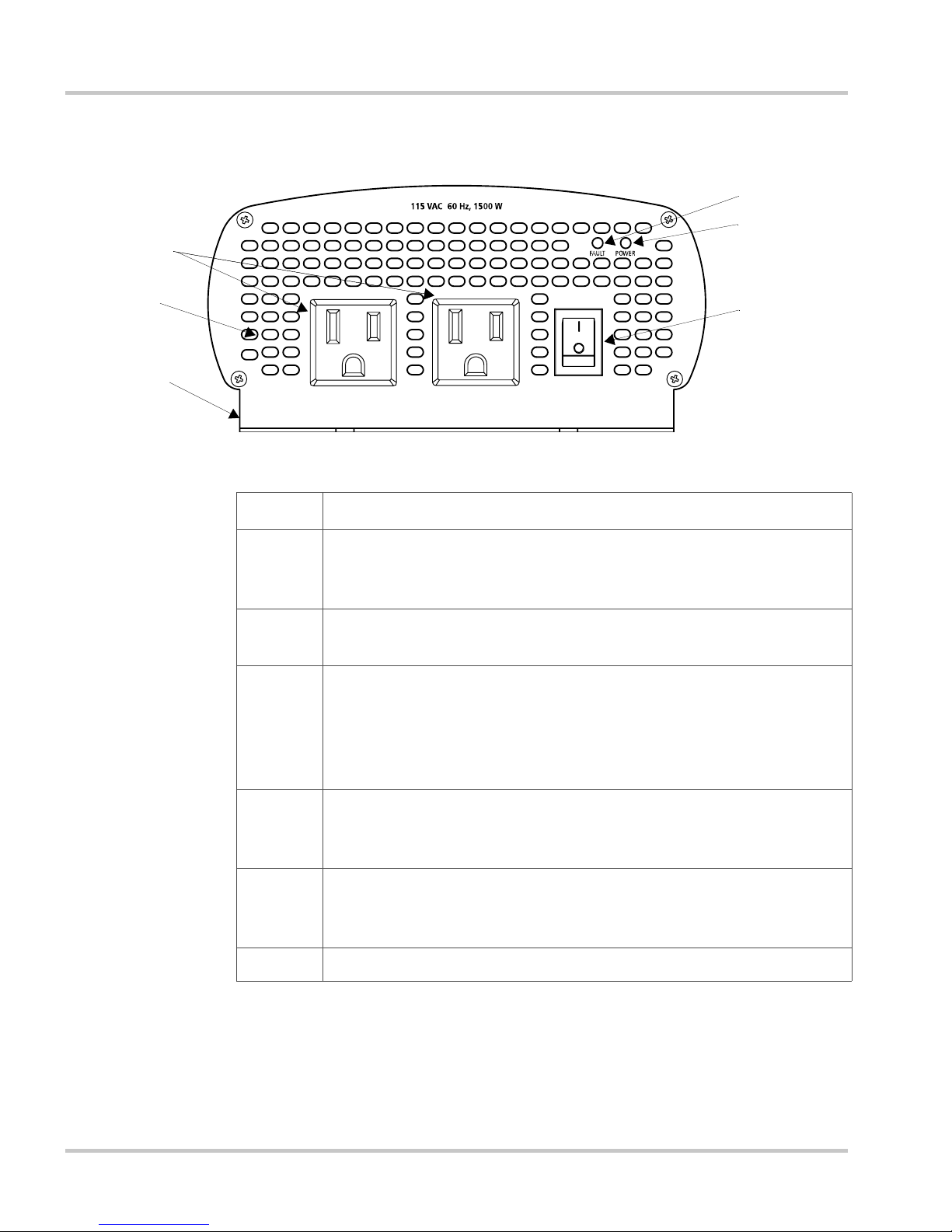
AC Panel
4
3
2
5
Figure 2-1
6
AC Panel
1
1
Feature Description
1
2 Power light is a green light indicating the On/Off Switch is on and
3 Fault light is a red light indicating the inverter has shut down due to
On/Off Switch turns the inverter’s control circuit on and off. This
switch is not a power disconnect switch. Disconnect AC and DC
power before working on any circuits connected to the inverter.
AC voltage is present at the inverter ’s AC outlets.
low or high battery voltage, unit overload, or over temperature.
NOTE: To restart the unit after a fault condition has occurred, turn
off the unit, then wait 3 to 5 seconds before turning the unit back on.
4 3-Prong AC Outlets:
5 Ventilation Openings must not be obstructed for the proper
6 Mounting Flange allows you to mount the inverter permanently.
2–2 975-0350-01-01
Duracell® 1500 delivers a combined total of 1500 watts of
continuous AC power across two outlets.
operation of the inverter. When the inverter is mounted, the
ventilation openings must not point up or dow n.
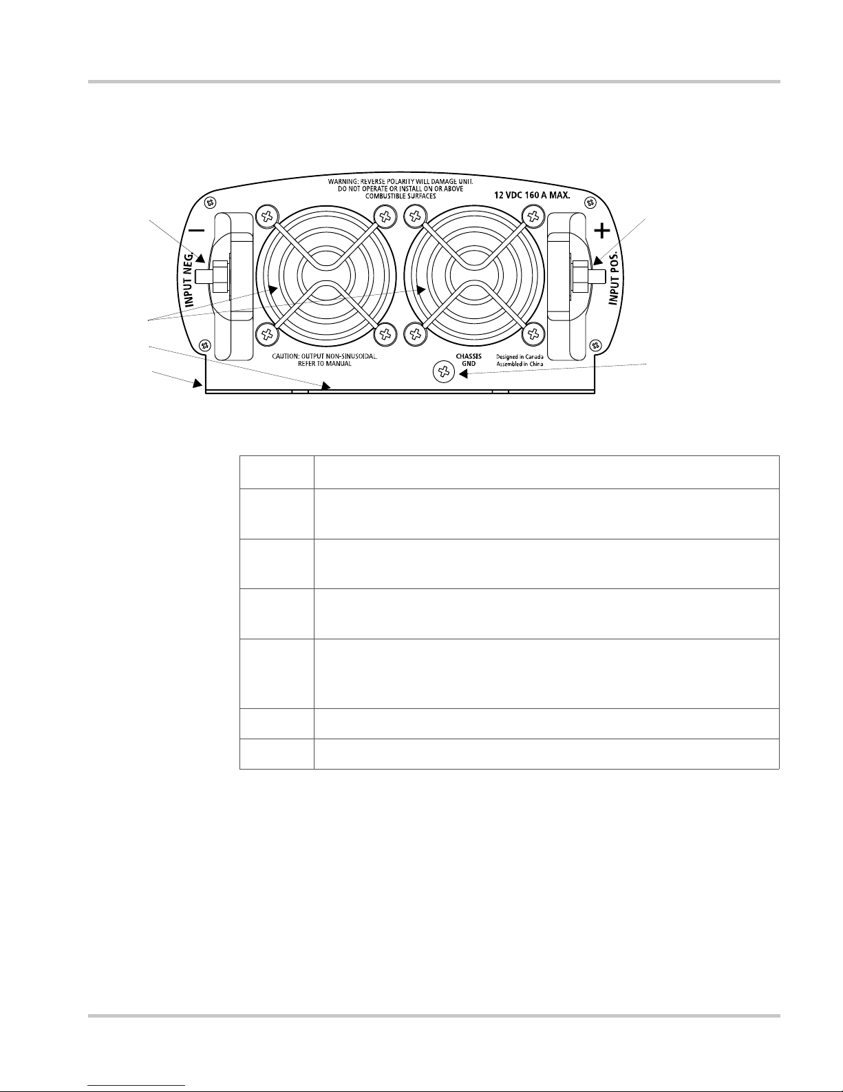
DC Panel
DC Panel
3
4
5
6
Figure 2-2
l
2
1
DC Panel
Feature Description
1 Chassis Ground Scr ew connects to vehicle chassis, DC grounding
bus or to engine’s negative bus.
2 Positive DC Cabling Terminal always connects to the cable
connected to the positive terminal of the battery.
3 Negative DC Cabling Terminal always connects to the cable
connected to the negative terminal of the battery.
4 Ventilation Opening must not be obstructed for the proper
operation of the inverter. When the inverter is mounted, the
ventilation opening must not point up or down.
5 Serial number of your unit (on center flange).
6 Mounting Flange allows you to mount the inverter permanently.
975-0350-01-01 2–3

2–4

3 Installation
Chapter 3 provides information on cables and fuses to help you plan for
your installation and provide procedures for installing the Duracell®
1500.
Xantrex highly recommends that you read the entire chapter before
beginning the installation procedures so that you can plan an installation
that is suited to your power needs.
Designing Your Installation
Before doing anything else, you need to determine how you are going to
use your Duracell® 1500, and then design a power system that will give
you maximum performance. The more thorough your planning, the better
your power needs will be met. In particular, you will need to:
• Be aware of installation codes
• Calculate your battery requirements
• Choose an effective charging system
• Choose an appropriate location
• Calculate the cable size for your Duracell® 1500
• Select the correct fuses or circuit breakers
Study Figure 3-1, “Configuration for Normal Loads” on page 3–2 and
Figure 3-2, “Configuration for Heavy Loads” on page 3–3 for an example
of a setup for normal or heavy loads in a vehicle. When you have decided
upon your configuration, then you can calculate battery requirements.
3–1
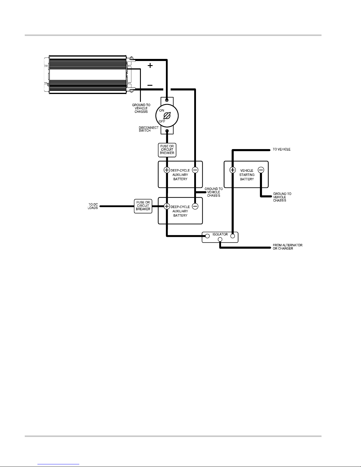
Installation
Figure 3-1
Configuration for Normal Loads
3–2 975-0350-01-01
 Loading...