


MODEL HT-3915
Home Theater System
Turns Your DVD Player Into
A Home Theater Surround Sound System
The Perfect Sound System for Your DVD Player
•Just add your TV & DVD player; everything else is in the box.
•Incredible surround sound, perfect for DVD viewing & enhanced TV game experience.
•Also provides superior sound for your computer
 PLEASE READ CAREFULLY BEFORE USE
IB-HT3915-WM-E-013004
SAFETY INSTRUCTIONS
WARNING
TO PREVENT FIRE OR SHOCK HAZARD, DO NOT USE THE PLUG WITH
AN EXTENSION CORD, RECEPTACLE OR OTHER OUTLET UNLESS THE
BLADES CAN BE FULLY INSERTED TO PREVENT BLADE EXPOSURE. TO
PREVENT FIRE OR SHOCK HAZARD, DO NOT EXPOSE THIS APPLIANCE
TO RAIN OR MOISTURE.
WARNING
The lightning flash with arrowhead symbol, within an equilateral triangle, is intended to alert the user to the presence of uninsulated “ dangerous voltage” within the product’s enclosure that may be of sufficient magnitude to constitute a risk of electric shock to persons.
RISK OF ELECTRIC SHOCK
DO NOT OPEN
WARNING: TO REDUCE THE RISK OF ELECTRIC SHOCK, DO NOT REMOVE COVER (OR BACK). NO USER SERVICEABLE PARTS INSIDE. REFER SERVICING TO QUALIFIED SERVICE PERSONNEL.
The exclamation point within an equilateral triangle is intended to alert the user to the presence of important operating and maintenance (servicing) instructions in the literature accompanying the appliance.
SEE BOTTOM OF THE MAIN SET.
IMPORTANT SAFETY INSTRUCTIONS
1.Read these instructions.
2.Keep these instructions.
3.Heed all warnings.
4.Follow all instructions.
5.Do not use this apparatus near water.
6.Clean only with dry cloth.
7.Do not block any ventilation openings, install in accordance with the manufacturer’s instructions.
8.Do not install near any heat sources such as radiators, heat registers, stoves, or other apparatus (including amplifiers) that produce heat.
9.Do not defeat the safety purpose of the polarized or grounding-type plug. A polarized plug has two blades with one wider than the other. A grounding type plug has two blades and a third grounding prong. The wide blade or
the third prong are provided for your safety. If the provided plug does not fit into your outlet, consult an electrician for replacement of the obsolete outlet.
10.Protect the power cord from being walked on or pinched particularly at plugs, convenience receptacles, and the point where they exit from the apparatus.
11.Only use attachments/accessories specified by the manufacturer. 12.Unplug this apparatus during lightning storms or when unused for long
periods of time.
13.Refer all servicing to qualified service personnel. Servicing is required when the apparatus has been damaged in any way, such as power-supply cord or plug is damaged, liquid has been spilled or objects have fallen into the apparatus, the apparatus has been exposed to rain or moisture, does not operate normally or has been dropped.
14.This appliance shall not be exposed to dripping or splashing water and that no object filled with liquid such as vases shall be placed on the apparatus.
Do not apply oil or petroleum products or solvents to any part of this set.
Cleaning the Cabinet
Clean the cabinet and controls with a very dry or slightly moistened soft cloth. Do not use any type of abrasive pad, scouring powder, or solvents, such as alcohol or benzine.
1
MODEL HT-3915
AC ~ 120V 60Hz POWER CONSUMPTION: 90 Watts
MADE IN CHINA
SEE BOTTOM OF THE MAIN SET.
FCC NOTE
This equipment has been tested and found to comply with the limits for a Class B digital device, pursuant to Part 15 of the FCC rules. These limits are designed to provide reasonable protection against harmful interference in a residential installation. This equipment generates, uses and can radiate radio frequency energy and, if not installed and used in accordance with the instructions, may cause harmful interference to radio communications . However, there is no guarantee that interference will not occur in a particular installation. If this equipment does cause harmful interference to radio or television reception, which can be determined by turning the equipment off and on, the user is encouraged to try to correct the interference by one or more of the following measures.
-Reorient or relocate the receiving antenna.
-Increase the separation between the equipment and receiver.
-Connect this equipment into an outlet on a circuit different from that to which the receiver is connected.
-consult the dealer or an experienced radio/ TV technician for help.
CAUTION
FCC Regulations state that unauthorized changes or modifications to this equipment may void the user’s authority to operate it.
PRECAUTIONS
ON SAFETY
Should any solid object or liquid fall into the Home Theater System, unplug the player, and have it checked by qualified personnel before operating it any further.
ON PLACEMENT OF YOUR HOME THEATER SYSTEM
•Do not leave the Home Theater in a location near a heat source, or in a place subject to direct sunlight, excessively dusty rooms or rooms with very high humidity.
•Do not place the Home Theater system on an inclined or unstable place.
•Do not place anything within 1 inch of the sides or 2 inches from the back of the cabinet. The heat sink fins must not be covered for the set to operate properly and prolong the life of its components.
IB-HT3915-WM-E-013004
INTRODUCTION
Thank you for purchasing this Home Theater Surround Sound System. This deluxe audio theater system turns your home into a virtual theater. In addition to the incredible surround sound of your current DVD player, this system also superbly enhances your other audio sources, such as a CD player, computer, VCR, or a cassette deck. The only thing you need to add is your own TV or other devices. We have designed this system to be easy to set up, but please, review this manual before you operate your system. Please have it handy while you are setting the system up; and keep it available for future reference, or in the unlikely event that you encounter any unexpected questions or problems. We have tried to keep this manual as simple as possible. It begins with how to connect the speakers, your TV, and other optional devices. It also includes instructions on how to position the speakers for the most natural surround sound. If you follow the instructions carefully you can have the system set up in about an hour.
This system was designed to provide you with many years of reliable operation with a minimum of care and maintenance. Every component in your system was perfect when it left our factory. If you experience any problem with the set-up or operation of this system, please review the Trouble Shooting Guide at the end of this manual before you contact the Customer Service Department at 1-800-315-5885.
All of the adjustable system settings have been preset at our factory for normal operation of the system. All you have to do is to sit back and enjoy the great home theater experience.
Later on, you may want to change some of the optional settings like speaker volume and balance settings. Instructions for changing them, are found later in this manual.
Basic Features & Benefits of this Home Theater System:
1.TV Game / Video Camera input jacks.
2.Includes audio inputs for DVD, AUX and GAME/CAMERA.
3.Customizable speaker level controls with indicators.
4.Powerful subwoofer provides real BOOM in your bass.
5.Deluxe easy-to-use remote control with batteries included.
6.LED indicators for DVD, AUXILIARY or GAME functions.
7.Designed for easy, mistake-proof color-coded speaker setup.
8.Compatible with computer sound systems - audio cable is included.
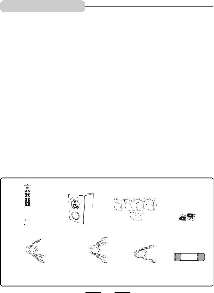
THIS SYSTEM CONTAINS
1 Remote Control |
1 Main Set (Subwoofer) |
5 Satellite Speakers |
2 “AAA” batteries |
1 Set of Audio cables with green |
1 Set of Audio Cables |
1 Yellow |
1 Spare |
3.5mm plug for Computer |
for DVD or AUX IN |
Video Cable |
Fuse |
Connection (or other Source |
(Red & White) |
|
|
with 3.5mm Jack) |
|
|
|
2 |
IB-HT3915-WM-E-013004 |

TABLE OF CONTENTS
• Getting Started |
|
Safety Instructions------------------------------------------------------------------------------------------------------------------------------------- |
1 |
Introduction----------------------------------------------------------------------------------------------------------------------------------------------- |
2 |
Location of Controls----------------------------------------------------------------------------------------------------------------------------------- |
4,5 |
Remote Control Operation--------------------------------------------------------------------------------------------------------------------------- |
6 |
• Connections |
|
Choose Your Connection----------------------------------------------------------------------------------------------------------------------------- |
7 |
Cables Needed to Connect Components to Your Home Theater System -------------------------------------------------------- |
7 |
Speaker system connections: |
|
Speaker system connections---------------------------------------------------------------------------------------------------------------------- |
8,9 |
Speaker Positioning Information------------------------------------------------------------------------------------------------------------------ |
10,11 |
TV Connections ---------------------------------------------------------------------------------------------------------------------------------------- |
12 |
TV + DVD Connections ----------------------------------------------------------------------------------------------------------------------------- |
13 |
TV + VCR Connections ----------------------------------------------------------------------------------------------------------------------------- |
14 |
TV + VCR + Satellite Receiver Connections ------------------------------------------------------------------------------------------------ |
15 |
TV + TV Game Connections ---------------------------------------------------------------------------------------------------------------------- |
16 |
TV + Video Camera Connections ---------------------------------------------------------------------------------------------------------------- |
17 |
AUX IN Connections --------------------------------------------------------------------------------------------------------------------------------- |
18 |
AM/FM Tuner Connections ------------------------------------------------------------------------------------------------------------------------ |
19 |
Computer Sound Connections -------------------------------------------------------------------------------------------------------------------- |
20 |
Amplifier in Main Unit |
|
General ---------------------------------------------------------------------------------------------------------------------------------------------------- |
21 |
Volume Adjustment------------------------------------------------------------------------------------------------------------------------------------- |
22 |
• Listening Mode |
|
5.1 Channel and Stereo Modes ------------------------------------------------------------------------------ ------------------------------------ |
23 |
• Trouble Shooting------------------------------------------------------------------------------------------------------------------------ |
24 |
• Specifications ------------------------------------------------------------------------------------------------------------------------------- |
25 |
3 |
IB-HT3915-WM-E-013004 |
LOCATION OF CONTROLS
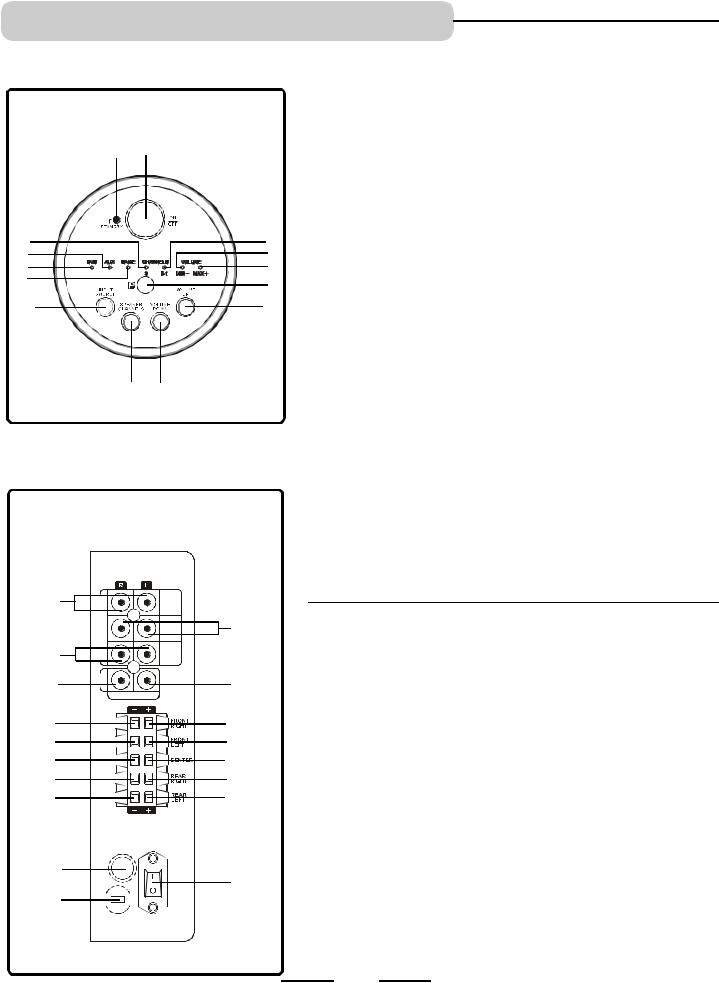
CONTROL PANEL
(ON THE FRONT OF THE SUBWOOFER)
2 1
3 |
14 |
4 |
13 |
5 |
12 |
6 |
11 |
|
|
7 |
10 |
8 9
BACK OF MAIN SET (SUBWOOFER)
15 |
|
|
16 |
17 |
|
19 |
18 |
20 |
20 |
21 |
21 |
22 |
22 |
23 |
23 |
24 |
24 |
26 |
25 |
|
|
27 |
|
1.ON / OFF button - Press to switch the set to on or off mode.
2.STANDBY indicator - This indicator has 2 modes: flashing and steadily on (slow flashing indicates the set is in standby, steadily on indicates the set is on). When the set is turned to ON, pressing the ON/STANDBY button on the REMOTE CONTROL will turn the set to the standby mode, the indicator will become slow flashing.
NOTE: The rear main power switch must be ON.
3.2 CHANNEL indicator - When the listening mode is 2 channels, this indicator will light up. To change, press the SPEAKER CHANNELS button.
4.AUX indicator - For AUX IN sound use, press the INPUT SOURCE button on the main set till this lights or press the SOURCE button on your REMOTE control.
5.DVD indicator - For DVD sound use, press the INPUT SOURCE button on the main set till this lights or press the SOURCE button on your REMOTE control till this lights.
6.GAME indicator - For TV GAME or VIDEO CAMERA use, press the INPUT SOURCE button on the main set till this lights or press the SOURCE button on your REMOTE control.
7.INPUT SOURCE button - Press several times to select the sound input source you want: DVD, AUX or GAME.
8.SPEAKER CHANNELS button - Press to select 2 channel or 5.1 channel listening mode.
9.VOLUME DOWN button - Decreases the volume level of all speakers. 10. VOLUME UP button - Increases the volume level of all speakers.
11.REMOTE SENSOR - Receives the signal from the REMOTE CONTROL (aim the REMOTE control towards this sensor).
12.VOLUME MAX. indicator - This indicator lights up when the MASTER VOLUME is at its maximum level, also it will flash confirming you pressed the VOLUME UP button of  either the SUBWOOFER, or CENTER, or REAR, or the MASTER.
13.VOLUME MIN. indicator - This indicator lights up when the MASTER VOLUME is at its minimum level, also it will flash confirming you pressed
the VOLUME DOWN button of  either the SUBWOOFER, or CENTER, or REAR, or the MASTER.
14.5.1 CHANNEL indicator - When the listening mode is 5.1 channels, this indicator will light up. To change, press the SPEAKER CHANNELS button.
15.DVD AUDIO INPUT jacks - Connect to the audio output of a DVD player to have 5.1 channel surround sound.
16.AUX INPUT jacks - Connect to the audio output of a tape deck or other component’s output.
17.GAME/CAMERA AUDIO INPUT jacks - Connect to the audio output jack of a TV game or video camera.
18.VIDEO INPUT jack - For connection of a video signal from a TV game, or video camera, or other source.
19.VIDEO OUT jack - Connect to your TV’s video input jack. (If your TV has no VIDEO jack, you have to buy a VIDEO RF MODULATOR.)
20.FRONT RIGHT SPEAKER jacks - Connect the FRONT RIGHT SPEAKER to the red and black terminals.
21.FRONT LEFT SPEAKER jacks - Connect the FRONT LEFT SPEAKER to the red and black terminals.
22.CENTER SPEAKER jacks - Connect only the CENTER SPEAKER to the blue and black terminals.
23.REAR RIGHT SPEAKER jacks - Connect the REAR RIGHT SPEAKER to the grey and black terminals.
24.REAR LEFT SPEAKER jacks - Connect the REAR LEFT SPEAKER to the grey and black terminals.
25.POWER switch - Press to power the set on or off.
NOTE: This switch must be ON in order to be able to use the ON/STANDBY button on the REMOTE CONTROL.
26.FUSE HOLDER with screw cover.
27.AC LINE CORD - Connect to a 120V/60Hz AC standard wall outlet.
4 |
IB-HT3915-WM-E-013004 |
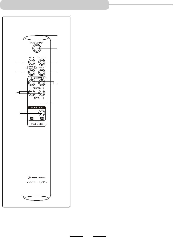
LOCATION OF CONTROLS
REMOTE CONTROL
|
1 |
|
2 |
5 |
3 |
6 |
4 |
|
7 |
8 |
|


 9
9
10 

1.IR DIODE - Sends the signal to the set. Do not block or cover this.
2.ON/STANDBY button - Switches the player from STANDBY to ON or ON to STANDBY (if the main POWER of the set is ON).
3.SOURCE button - Press to select the sound input source you want: DVD, AUX or GAME.
4.RESET button - Press to adjust all speakers’ output to the factory’s default settings.
5.MUTE button - Instantly turns off the sound. Press again to restore the sound.
6.SPEAKER CHANNELS button - Press to select 2 channel or 5.1 channel listening mode.
7.SUBWOOFER UP & DOWN VOLUME buttons - Press to adjust the individual SUBWOOFER’s sound level.
8.CENTER UP & DOWN VOLUME buttons - Press to adjust the individual CENTER speaker’s sound level.
9.REAR UP & DOWN VOLUME buttons - Press to adjust the REAR LEFT/RIGHT speakers’ sound level.
10.MASTER VOLUME UP & DOWN buttons - Press to adjust the sound level of all speakers.
SEE NEXT PAGE FOR REMOTE CONTROL BATTERY INSTALLATION.
5 |
IB-HT3915-WM-E-013004 |
REMOTE CONTROL OPERATION
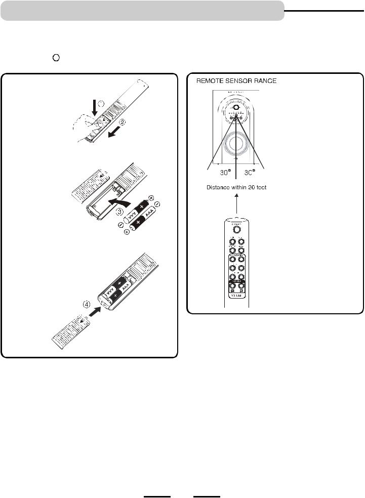
Battery Installation
Remove the BATTERY COMPARTMENT DOOR of the REMOTE CONTROL and insert 2 size “AAA” alkaline batteries (included) according to the + and  markings inside the BATTERY COMPARTMENT of the REMOTE CONTROL unit.
Gently push here and slide to open the BATTERY DOOR.
Slide door down.
Insert 2 size “AAA” batteries as shown (included).
Remember, the spring touches the  side of each battery.
Remote Control Operating Range
Point the REMOTE CONTROL unit within 20 feet from the remote control sensor and facing the front of the HOME THEATER SYSTEM.
Remember to point the REMOTE CONTROL in the direction of the HOME THEATER’s sensor, not the TV set or the DVD player.
Replace the door.
Tips on Battery Use
•Reversing polarities will damage the batteries and possibly your REMOTE. Be sure to follow polarity  and
and  as indicated.
•Do not mix different types of batteries together (Alkaline, Carbon-Zinc, Nickel-Cadmium etc.), or old batteries with new ones.
•When not in use for an extended period of time (over 60 days), remove the batteries to prevent possible acid leakage or corrosion resulting in possible damage to your REMOTE CONTROL.
•When the batteries have become discharged, they must be disposed of in a safe manner that complies with all applicable laws.
•Installation of batteries should only be done by an adult (for safety).
Point the REMOTE CONTROL at the Home Theater’s Front
Make sure there is a clear path between the REMOTE CONTROL and the HOME THEATER SYSTEM so that the signal is not blocked.
Tips on REMOTE CONTROL Operation
•The REMOTE control’ s operating distance may vary according to the brightness of the room.
•Do not point bright lights at the REMOTE CONTROL SENSOR (like laser pointers).
•Do not place objects between the REMOTE CONTROL unit and the REMOTE SENSOR.
•Do not use this REMOTE CONTROL while simultaneously using the remote control unit of any other equipment, the signals may mix.
•Sometimes your TV’s remote may cause an LED to flash, you can ignore this.
6 |
IB-HT3915-WM-E-013004 |

CONNECTIONS
Choose Your Connection
There are several ways to connect your Home Theater System. Please use the following chart to determine which connection is the best for you. Turn to the appropriate page and connect your Home Theater System.
|
|
|
R |
|
|
EATE |
|
|
E TH |
UND |
|
HOM |
|
||
|
|
D SO |
|
OUN |
|
||
SURR |
|
EM |
|
|
SYST |
|
|
COMPONENTS
NOTE:
This only applies if your
TV has audio out jacks.
TV
+
HOME THEATER (only)
TV/DVD
+
HOME THEATER
TV/VCR
+
HOME THEATER
TV/VCR
+
HOME
THEATER
+
SATELLITE
TV
+
HOME THEATER
+
TV GAME or
VIDEO CAMERA
CABLES
NEEDED
•Audio (included)
•Video (included)
•Audio (included)
•Video (included)
•Audio (included)
•Video (included)
•Audio (included)
•Video (special, not included)
•Audio (special, not included)
GO TO ...
Page 12
Page 13
Page 14
Page 15
Page 16,17
TAPE RECORDER/PLAYER
|
AM/FM TUNER |
|
|
PC |
or |
|
Page |
|
other AUX |
• Audio (included) |
|
|
18,19,20 |
||
|
DEVICE |
|
|
|
|
|
|
|
+ |
|
|
|
HOME THEATER |
|
|
Cables Needed to Connect Components to Your Home Theater System
The pictures below show the cables needed for the connections represented in this booklet.
NOTE: Audio cables are usually sold as a bundled set, but the connection sketches in this booklet show each cable separately for better visibility. You will need additional cables to connect everything shown above. Check your other equipments’ booklets to see what cables are needed. 
Yellow Video cable |
Red & White Audio cables |
(one set included) |
(one set included, most installations |
|
will need these) |
1 Set of Audio cables with |
Speaker Wires (5 sets |
|
green 3.5mm plug for Computer |
||
are attached to the back |
||
Connection (or other Source |
||
of the speakers) |
||
with 3.5mm Jack) |
||
|
7 |
IB-HT3915-WM-E-013004 |
 Loading...