

Page 1
SUPPLEMENT
SERVICE MANUAL
This service manual shows only the differences between
the model DWT1905 and the original model ST419E.
All other information is described in the service manual
of the model ST419E.
19″ COLOR
TELEVISION
DWT1905
TABLE OF CONTENTS
The difference from the original model ST419E in ELECTRICAL
ADJUSTMENT INSTRUCTIONS . . . . . . . . . . . . . . . . . . . . . . . . . . . . . . . . . . . . 1-1
Block Diagrams . . . . . . . . . . . . . . . . . . . . . . . . . . . . . . . . . . . . . . . . . . . . . . . . . . . . . 2-1
Schematic Diagrams / CBA's and Test Points . . . . . . . . . . . . . . . . . . . . . . . . . . . . . . 3-1
Different parts from the original model (ST419E) . . . . . . . . . . . . . . . . . . . . . . . . . . . 4-1
VIDEO AUDIO EARPHONE
VOLUME
MENU
CHANNEL
P
O
W
E
R
Page 2

The difference from the original model ST419E in ELECTRICAL ADJUSTMENT INSTRUCTIONS
For 3-1. Setting for Data Values, “VIDEO TONE---set to” becomes “ON”,
since SHARP function is installed in this model.
3-1. Setting for Data Values
General
1. Enter the Service mode.
2. To select the data value, press "VOL p" button on
the service remote control unit.
3. To set the following each data value, press "CH o
/ p" buttons on the service remote control unit.
7F --- set to 7F
LANGUAGE --- set to SPA/FRA
ACCESS CODE --- set to OFF
SOUND TYPE --- set to MONO
VIDEO TONE --- set to ON
FM-MODE --- set to OFF
V-OUT --- set to OFF
VIDEO --- set to V1
AV-MEMO --- set to OFF
STABLE SOUND --- set to OFF
FILTER --- set to OFF
PROTECTOR --- set to 1000
YUVMEMORY --- set to OFF
NO SIGNAL BRT --- set to 0
A-MUTE POL --- set to L
V-MENU --- set to OFF
1-1 L2314EA
Page 3
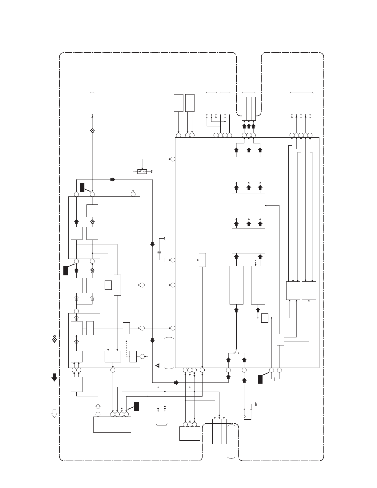
BLOCK DIAGRAMS
IF/Video/System Control Block Diagram
TO
AUDIO/POWER
CONTROL BLOCK
KEY
SWITCH
REMOTE
SENSOR
TU-AUDIO
RCV101
70
69
66
TO
PROTECT-1
POWER SUPPLY BLOCK
PROTECT-2
P-ON-H
79
PROTECT-1
TO
PROTECT-2
676876
CRT/H.V. BLOCK
PROTECT-3
TO
BLUE5
WH301A
525150
CRT/H.V. BLOCK
WH301B
GREEN4
RED3
TO
CRT/H.V. BLOCK
ACL
H-DRIVE
FBP
V-DRIVE
5346453837
V-RAMP-F/B
MAIN CBA
WF1
CF31
AUDIO SIGNAL
IC31 (IF SIGNAL PROCESS)
VIDEO SIGNALRF/IF SIGNAL
SF1
1
EQ
AMP
2
4.5MHz
TRAP
4
VIDEO
DET
VIF
AMP
16
17
SAW
FILTER
WF6
CF32
9
AF
AMP
FM
DET
7
4.5MHz
FILTER
VCO
LPF
RF
AGC
14
IF AGC DET
AFT
Q31
6
VCO F/B
AMP
RCV-IN
KEY-IN2
KEY-IN1
63
X301
3.58MHz
16
73 75
AFT AGC-IN EXT-H
11 13 18
SCL
TV MICON/VIDEO
/AUDIO/CHROMA
/DEFLECTION
IC111
SDA
58
56
72 I2C-OPEN
VCXO
32
P-ON-H
PROTECT-1
PROTECT-2
PROTECT-3
TUNER
26
RGB DRIVE
/CUT OFF
OSD SW
/CONTRAST
RGB MATRIX
/COLOR CONT
LUMINANCE
PROCESS
CIRCUIT
LINE
24
/H.V. BLK
/BRIGHTNESS
CHROMINANCE
PROCESS
CIRCUIT
LPF
WF2
V-SYNC
PROCESS
CIRCUIT
CIRCUIT
H-SYNC
PROCESS
OSD
14
11
TU1
IF
4
SCL
SDA
AGC
EXT.CLK
SCL
TO
SDA
AUDIO/POWER
CONTROL BLOCK
IC151
(MEMORY)
7
CS
2-1
6
SCL
5
SDA
CN301(NO CONNECTION)
SDA 4
I2C-OPEN 2
SCL 5
CN301 is used for
adjustment at factory
JK701
VIDEO-IN
L2314BLIF
WF16
8
1115
Page 4
SCHEMATIC DIAGRAMS / CBA'S AND TEST POINTS
Standard Notes
Many electrical and mechanical parts in this chassis have special characteristics. These characteristics often
pass unnoticed and the protection afforded by them cannot necessarily be obtained by using replacement
components rated for higher voltage, wattage, etc. Replacement parts that have these special safety
characteristics are identified in this manual and its supplements; electrical components having such features are
identified by the mark “#” in the schematic diagram and the parts list. Before replacing any of these components,
read the parts list in this manual carefully. The use of substitute replacement parts that do not have the same
safety characteristics as specified in the parts list may create shock, fire, or other hazards.
Notes:
1. Do not use the part number shown on these drawings for ordering. The correct part number is shown in the
parts list, and may be slightly different or amended since these drawings were prepared.
2. All resistance values are indicated in ohms (K = 10
3. Resistor wattages are 1/4W or 1/6W unless otherwise specified.
4. All capacitance values are indicated in µF (P = 10
5. All voltages are DC voltages unless otherwise specified.
Note of Capacitors:
ML --- Mylar Cap. PP --- Metallized Film Cap. SC --- Semiconductor Cap. L --- Low Leakage type
Temperature Characteristics of Capacitors are noted with the following:
B --- ±10% CH --- 0±60 ppm/°C CSL --- +350~-1000 ppm/°C
3
, M = 106).
-6
µF).
Tolerance of Capacitors are noted with the following:
Z --- +80~-20%
Note of Resistors:
CEM --- Cement Res. MTL --- Metal Res. F --- Fuse Res.
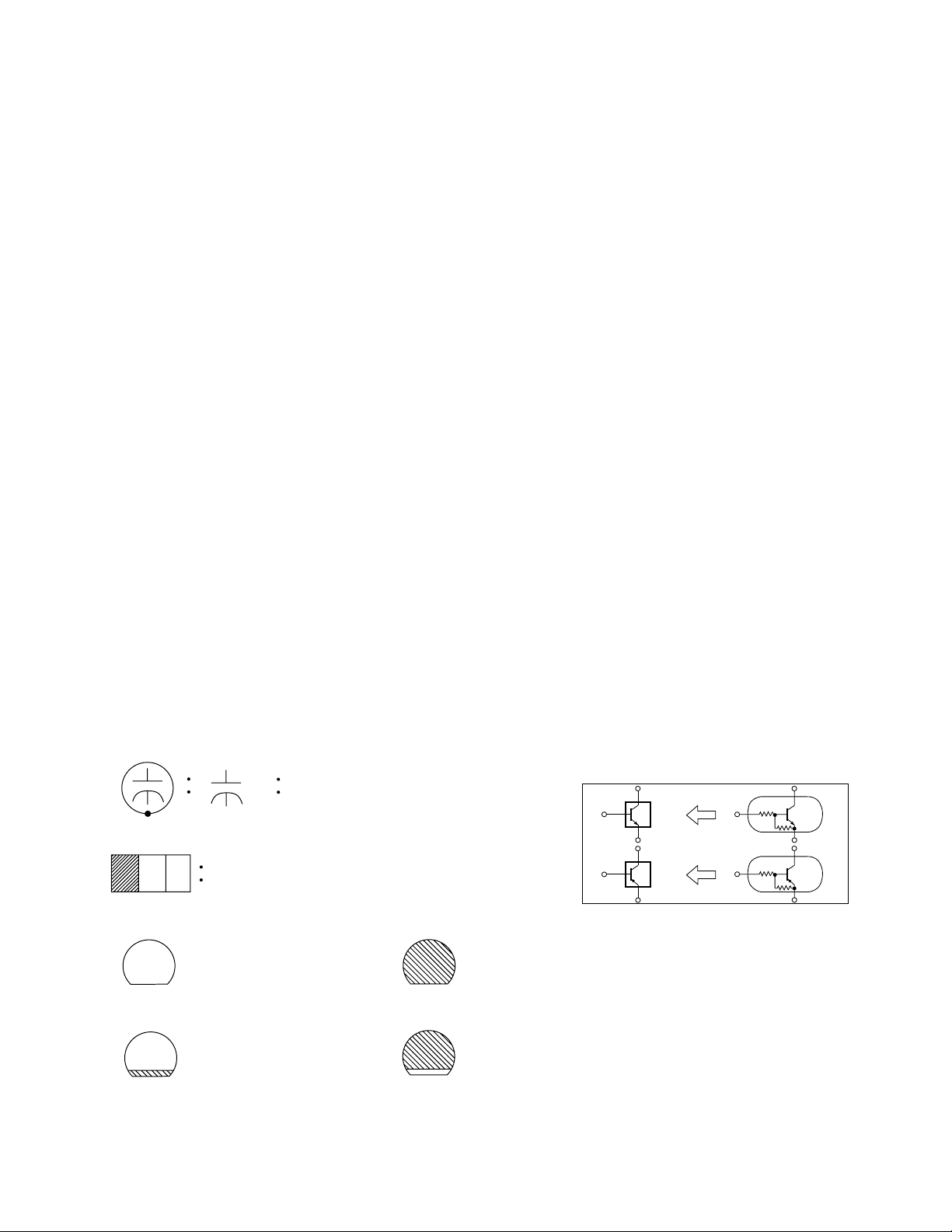
Capacitors and transistors are represented by the following symbols.
CBA Symbols
(Top View) (Bottom View)
+
Electrolytic Capacitor
(Bottom View)
Transistor or Digital Transistor
E C B
(Top View)
NPN Transistor
E C B
(Top View)
(Top View)
PNP Transistor
E C B
(Top View)
Schematic Diagram Symbols
Digital Transistor
E C B
NPN Digital Transistor
PNP Digital Transistor
E C B
3-1 L15N_SC
Page 5

LIST OF CAUTION, NOTES, AND SYMBOLS USED IN THE SCHEMATIC DIAGRAMS ON
THE FOLLOWING PAGES:
1. CAUTION:
CAUTION: FOR CONTINUED PROTECTION AGAINST RISK OF FIRE, REPLACE ONLY WITH SAME
TYPE_A,_V FUSE.
ATTENTION: UTILISER UN FUSIBLE DE RECHANGE DE MÊME TYPE DE_A,_V.
2. CAUTION:
Fixed Voltage (or Auto voltage selectable) power supply circuit is used in this unit.
If Main Fuse (F601) is blown, first check to see that all components in the power supply circuit are not
defective before you connect the AC plug to the AC power supply. Otherwise it may cause some components
in the power supply circuit to fail.
3. Note:
1. Do not use the part number shown on the drawings for ordering. The correct part number is shown in the
parts list, and may be slightly different or amended since the drawings were prepared.
2. To maintain original function and reliability of repaired units, use only original replacement parts which are
listed with their part numbers in the parts list section of the service manual.
4. Voltage indications on the schematics are as shown below:
Plug the TV power cord into a standard AC outlet.:
2
(Unit: Volt)
1
5.0
(3.0)
3
5.0
(3.0)
Power on mode
Power off mode
5. How to read converged lines
1-D3
Distinction Area
Line Number
(1 to 3 digits)
Examples:
1. "1-D3" means that line number "1" goes to the line number
"1" of the area "D3".
2. "1-B1" means that line number "1" goes to the line number
"1" of the area "B1".
6. Test Point Information
: Indicates a test point with a jumper wire across a hole in the PCB.
: Used to indicate a test point with a component lead on foil side.
: Used to indicate a test point with no test pin.
: Used to indicate a test point with a test pin.
Voltage
Indicates that the voltage
is not consistent here.
3
2
1
AREA D3
1-B1
AREA B1
1-D3
ABCD
3-2 L15N_SC
Page 6

Main 2/3 Schematic Diagram
For continued protection against risk of fire,
replace only with same type 4 A, 125V fuse.
CAUTION ! :
ATTENTION : Utiliser un fusible de rechange de même type de 4A, 125V.
4A/125V
NOTE:
The voltage for parts in hot circuit is measured using
hot GND as a common terminal.
MAIN 2/3
Ref No. Position
IC31
I-3
IC601
I-1
Q31
H-4
Q601
J-2
Q602
J-1
Q662
I-1
Q671
H-2
Q675
H-1
Q676
H-1
Q681
G-2
Q682
G-1
Q683
G-1
CN691 K-2
VR661 I-1
TRANSISTORS
ICS
CONNECTOR
VARIABLE RESISTOR
CAUTION !
Fixed voltage (or Auto voltage selectable) power supply circuit is used in this unit.
If Main Fuse (F601) is blown , check to see that all components in the power supply
circuit are not defective before you connect the AC plug to the AC power supply.
Otherwise it may cause some components in the power supply circuit to fail.
3-3
1 NOTE:
*
These components (C643, C642, JS642)
can be used in any models.
However, you cannot mix components under
Group A with the ones under Group B.
You can choose either Group. The difference
between Group A and Group B is shown below.
Group A Group B
C643
C642
JS642
0.01/250V
0.01/250V
Not Used
4700P/250V
Not Used
WIRE
L2314SCM2
Page 7

NOTE:
The voltage for parts in hot circuit is measured using
hot GND as a common terminal.
Main CBA Top View
MAIN CBA
Ref No. Position
IC31
B-1
IC111
D-1
IC151
E-2
IC551
B-2
IC601
C-4
IC801
E-1
Q31
C-1
Q111 E-2
Q321 C-1
Q571
B-3
Q572
B-2
Q601
B-4
Q602
B-4
Q662
C-3
Q671
C-3
Q675
C-2
Q676
C-2
Q681
D-3
Q682
D-3
Q683
D-3
CN571
A-3
CN691
C-4
CN801
D-1
WH301A C-2
WH501A A-2
TP300
A-3
TP601
A-4
VR661 A-1
ICS
VARIABLE RESISTOR
CONNECTORS
TEST POINTS
TRANSISTORS
CAUTION !
Fixed voltage (or Auto voltage selectable) power supply circuit is used in this unit.
If Main Fuse (F601) is blown , check to see that all components in the power supply
circuit are not defective before you connect the AC plug to the AC power supply.
Otherwise it may cause some components in the power supply circuit to fail.
FOCUS-VR
(UPPER SIDE)
SCREEN-VR
(LOWER SIDE)
TP300
GND
VR661
+B ADJ
TP601
+B
4A/125V
CAUTION ! :
For continued protection against risk of fire,
replace only with same type 4 A, 125V fuse.
ATTENTION : Utiliser un fusible de rechange de même type de 4A, 125V.
3-4
Because a hot chassis ground is present in the power
supply circuit, an isolation transformer must be used.
Also, in order to have the ability to increase the input
slowly,when troubleshooting this type power supply
circuit, a variable isolation transformer is required.
BL2300F01011-1
Page 8

Main CBA Bottom View
NOTE:
The voltage for parts in hot circuit is measured using
hot GND as a common terminal.
CAUTION !
Fixed voltage (or Auto voltage selectable) power supply circuit is used in this unit.
If Main Fuse (F601) is blown , check to see that all components in the power supply
circuit are not defective before you connect the AC plug to the AC power supply.
Otherwise it may cause some components in the power supply circuit to fail.
4A/125V
CAUTION ! :
ATTENTION : Utiliser un fusible de rechange de même type de 4A, 125V.
For continued protection against risk of fire,
replace only with same type 4 A, 125V fuse.
Because a hot chassis ground is present in the power
supply circuit, an isolation transformer must be used.
Also, in order to have the ability to increase the input
slowly,when troubleshooting this type power supply
circuit, a variable isolation transformer is required.
WF8
Q571
Base
WF7
Q572
Collector
WF9
PIN 1
OF CN571
WF12
PIN 4
OF CN571
WF10
PIN 3
OF WH501A
WF11
PIN 7
OF IC551
WF1
PIN 2
OF IC31
WF16
PIN 8
OF TU1
WF6
PIN 9
OF IC31
WF2
PIN 14
OF IC111
3-5
BL2300F01011-1
Page 9

CRT CBA Top View CRT CBA Bottom View
CRT CBA
Ref No. Position
TRANSISTORS
Q501 B-2
Q502
Q503
CONNECTORS
CN501 A-1
WH301B B-1
WH501B B-1
B-2
B-2
WF13
Q503
Collector
WF5
Q503
Base
WF4
Q502
Base
WF14
Q502
Collector
WF3
Q501
Base
WF15
Q501
Collector
3-6
BL2300F01011-2
Page 10

Different parts from the original model (ST419E)
Ref. No. Description Part No.
MECHANICAL PARTS
A1 FRONT CABINET L2314UQ 1EM020170
A2 CONTROL PLATE L2314UQ 1EM220118
A4# RATING LABEL L2314UQ ---------A5 BRAND BADGE L2204UE 0EM408903
B3 Not Used
S1 CARTON L2314UQ 1EM420767
S6 SERIAL NO. LABEL L2314UQ ---------S7 LABEL, EAS(H3761UD) MAKER NO.ZLLFNSLE1 ---------X1# OWNERS MANUAL L2314UQ 1EMN20269
X2 REMOTE CONTROL NE142UD NE142UD
X4 SHEET RETURN STOP L2204UE 0EM408998
ELECTRICAL PARTS
MMA CBA 1ESA10705
C38 Not Used
C601# METALLIZED FILM CAP. 0.22µF/250V CT2E224MS037
C609 CERAMIC CAP. B K 1000pF/2KV CCD3DKD0B102
IC31 IC:VIF/SIF M61113FP TF0G QSZBA0SHT035
R38# CHIP RES.(1608) 1/10W J 12K Ω RRXAJB5Z0123
R132 Not Used
TU1 TUNER ENV56K02G3 UTUNNTUMS012
4-1 L2314PL
Page 11

DWT1905
L2314UQ
2005-04-06
 Loading...