


Water Filtration
Installation
Instructions
Reverse Osmosis Drinking Water Filtration System
Instrucciones de instalación
Sistema de filtración de agua potable por ósmosis inversa
Model Series WFRO60X-1 Serie del modelo WFRO60X-1
V4.4

Installation Instructions
Reverse Osmosis Drinking Water
Filtration System
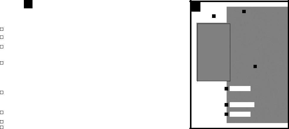
Parts & Hardware Included
ARO Filter System Head with Built-in Bracket
BQuickTwist™ Filters
CMounting Screws
DTank Connector
EWater Storage Tank
FKitchen Faucet Adapter
GEye Dropper
HPlumber’s Tape
|
|
I |
Restrictor |
|
Nitrate Test Strip |
J |
KDrain Connector
LDrain Connector Screws M Nuts
NFoam Seal
ORO Faucet Spout
PRO Faucet Body
QRO Faucet Base
R5’ of 1/4” Red Tube
(RO Faucet Body to RO Membrane Filter)
S6’ of 3/8” White Tube
(RO Faucet Body to RO System Head)
T 2.5’ of 3/8” Red Tube
|
|
|
|
|
(RO Faucet Body to Drain Connector) |
|
|
|
|
|
|
6’ of 1/4” White Tube |
|
|
|
|
U |
|||
|
|
|
|
|
(Kitchen Faucet Adapter to |
|
|
|
|
|
|
RO System Head) |
|
Tools & Materials Required |
|
|
|
|
||
|
|
Phillips Screwdriver |
|
|
|
Safety Glasses |
|
|
|
|
|||
|
|
|
|
|||
|
|
1/8" Drill Bit |
|
|
|
Masking Tape |
|
|
|
|
|||
|
|
Center Punch |
|
|
|
Newspaper or Towels |
|
|
|
|
|||
|
|
Adjustable Wrench |
|
|
|
Pencil |
|
|
|
|
|||
|
|
|
|
|||
|
|
Utility Knife |
|
|
|
Pan or Bucket |
|
|
|
|
|||
|
|
|
|
|||
|
|
File |
|
|
|
Compression Cap (Optional- |
|
|
|
|
|
||
|
|
|
||||
|
|
Tape Measure |
|
|
|
For Kitchen Faucet Spray |
|
|
|
||||
|
|
|
|
|
|
Hose Connector) |
Optional Materials |
|
|
|
Digital Air Pressure Gauge |
||
|
|
|
||||
|
|
|
||||
|
|
|
|
|||
Drill with 1/4" & 9/16" or 5/8" Drill Bits
Hollow-Wall Anchor Bolts or Toggle Bolts
Package Contents
|
|
F |
|
G |
|
|
A |
|
|
|
|
|
|
|
|
|
O |
B1 |
B3 |
J |
|
|
H Plumber’s Tape |
|
|
|
|
||
|
B2 |
|
|
|
|
|
|
|
|
|
I |
C |
K |
L |
|
N |
|
|
|
P |
|||
|
|
|
|
|
|
D |
|
|
|
|
|
|
|
M |
Q |
|
R |
|
|
|
|
|
|
E |
|
|
|
|
|
|
|
|
|
|
T |
|
|
S |
|
|
|
|
|
U |
|
|
|
Information & Assistance
866-709-2086 Toll Free |
|
‘How to Install’ Video - |
|
For Service Requests & Product Information |
email us at: |
||
FREE Download |
|||
Hours of Operation: 24 Hours/Day, 7 Days/Week |
waterfiltration@mail1.dupont.com |
||
800-441-7515 |
|
www.waterfiltration.dupont.com |
|
|
|
||
For Safety & Health Questions |
|
|
|
Protect Plus, LLC |
420 Third Avenue NW Hickory, NC 28601 |
|
|
|
|
|
For installations in Massachusetts, the Commonwealth of Massachusetts Plumbing Code CMR248 shall be adhered to. Codes in the state of Massachusetts require installation by a licensed plumber and do not permit the use of saddle valves.
DuPont™ Water Filtration would like to thank you for your recent purchase of the DuPont™ Reverse Osmosis Filtration System.
We greatly appreciate your business and the opportunity to assist you. Your satisfaction is the greatest importance to us. We hope that you will inform us if there is ever anything we can do to improve our products. Please contact us if you have any questions or if there is anything we can do to assist you with your new product.
Reverse Osmosis, also known as hyper filtration, is the most common treatment technology used by premium bottled water companies. It is effective in substantially reducing a very wide array of contaminants. The pores in a reverse osmosis membrane are approximately 0.025 micron in size (bacteria are 0.2 to 1 micron & viruses are 0.025 to 0.4 microns).
How Reverse Osmosis works –
Your new Reverse Osmosis (RO) system is composed of a 3-stage system manifold, a 3000 series pre-filter, the reverse osmosis membrane, a storage tank, a 3000 series post-filter and a faucet to deliver the filtered water to your countertop. First the water goes to the pre-filter, which is a replaceable cartridge that reduces chlorine, odor, sand, silt, dirt, and other sediments to improve the taste of your water. Next, the water flows to the Reverse Osmosis cartridge, which is a tightly wound membrane that reduces the total dissolved solids and organic matter. The water goes from the membrane into the storage tank. A diaphragm inside the tank keeps the water pressurized to about 30 psi when the tank is full. This is what provides the fast flow to the faucet. When the tank is empty, it should be pressurized to 5 – 7 psi. As water is drawn to the faucet, it flows from the storage tank through the final filter. This is a replaceable cartridge that reduces any remaining tastes and odors to provide cleaner great tasting drinking water to the faucet.
Your system also has an automatic shutoff valve to conserve water. When the storage tank is full and the faucet is not open, pressure closes the shutoff valve to stop flow of water with contaminants to the drain. After enough drinking water is drawn from the faucet, the pressure in the Reverse Osmosis system drops and the shutoff valve opens to allow the tank to be re-filled.
Reverse Osmosis uses a membrane that is semi-permeable, allowing cleaner water to pass through it, while rejecting the contaminants that are too large to pass through the tiny pores in the membrane. This quality reverse osmosis system uses a process known as cross-flow to allow the membrane to continually clean itself. As some of the fluid passes through the membrane the rest continues downstream, sweeping the rejected contaminants away from the membrane and down the drain. The process of reverse osmosis requires a driving force to push the water through the membrane - the pressure provided by your home’s water supply is sufficient: 40 to 100 psi.
What it removes –
Your Reverse Osmosis (RO) unit will reduce Chlorine, Odor, Particulates, Sediment, and improve taste, according to NSF 42 standards. It will also reduce Total Dissolved Solids (TDS), Pentavalent Arsenic, Hexavalent Chromium, Lead, Cadmium, Cysts, Nitrate Plus Nitrite, Nitrate, & Nitrite according to NSF 58 standards.
Thanks again for your purchase
~ The DuP ont Water Filtration Team
CAUTION
This filter must be protected from freezing, which can cause cracking of the filter and water leakage.
CAUTION
Because of the product’s limited service life and to prevent costly repairs or possible water damage, we strongly recommend that the housing be replaced every five years. If the head of the filter has been in use for longer than this period, it should be replaced immediately. Date the top of any new head to indicate the next recommended replacement date.
Plan Your Installation
It is recommended to read through the entire manual before beginning your installation.
Follow all steps exactly. Reading this manual will also help you get all the benefits from your system.
Your Reverse Osmosis Drinking Water System can be installed under a sink or in a
remote location. Typical remote sites are a basement or laundry room or utility room. Review the location options below and determine where you are going to install your system.
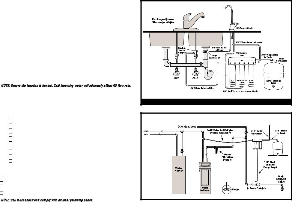
Under The Sink Location
The Reverse Osmosis Filter Assembly and storage tank are normally installed in a kitchen or bathroom sink cabinet. See Fig. 1.
A suitable drain point is needed for reject water from the Reverse Osmosis Filter.
Remote Location
You can also locate the Reverse Osmosis Filter Assembly and storage tank in a remote location away from the Reverse Osmosis Faucet. You will need a nearby water source and drain point. See Fig. 2.
N OTE: Ensure the loc ation is he ate d . Cold inc oming wate r will adve rse ly affe c t RO flow rate .
Check Space Requirements
Check size and position of items for proper installation into location chosen.
Overview and Site Preparation
There are seven easy steps to installing your Drinking Water system. They are as follows: STEP 1 - Install Kitchen Faucet Adapter
STEP 2 - Install RO Drain Connector
STEP 3 - Install RO Filter Assembly
STEP 4 - Install Water Storage Tank
STEP 5 - Install RO Faucet
STEP 6 - Connect Tubing for Water Supply Line from Kitchen Faucet Adapter to RO System Head STEP 7 - Connect Tubing Continued
STEP 8 - Install RO System and Drain in Remote Location
STEP 9 - Sanitize, Pressure Test, Purge System
Prepare Site For Installation
1Before starting, close the cold water shut-off valves.
2Temporarily place tank and filter assembly into cabinet. Double check position of items and space required for proper installation.
3Remove tank and filter from cabinet and set aside.
N OTE: You m ust che ck and c om ply with all loc al plum bing code s.
WFRO60X-1
Fig. 1 |
NOTE: DO NOT CONNECT 3/8” RED DRAIN TUBING TO DRAIN WITH A GARBAGE DISPOSAL. |
Fig. 2 |
|
3 |
V4.4 |
STEP |
|
|
|
|
|
|
1 |
|
|
|
|||
|
|
1 |
|
|||
|
||||||
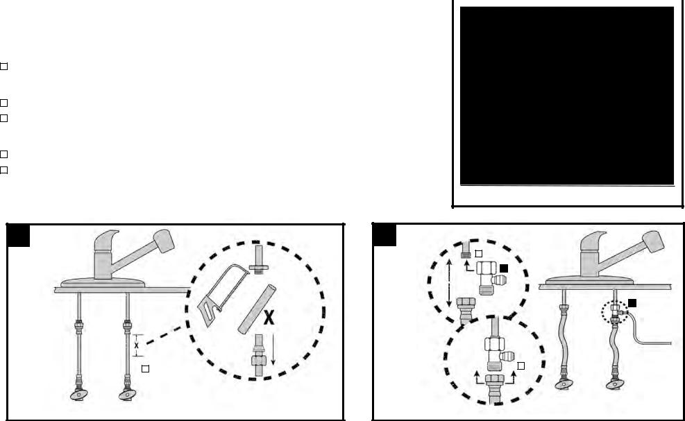
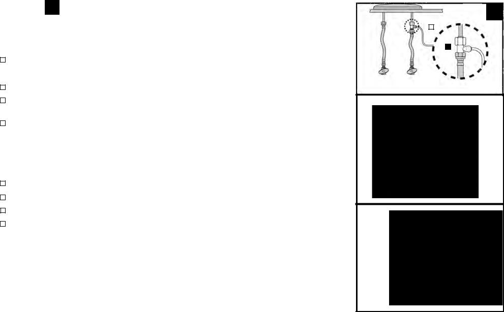
Install Kitchen Faucet Adapter |
|
|
|
|||
|
|
|
||||
CHOOSE TYPE OF WATER FITTING TO INSTALL |
|
|
|
|||
1Locate the cold water line in the sink cabinet. Turn off the cold water supply to the sink.
NOTE: If uncertain about which line supplies the cold water, turn on the hot water to the faucet. Allow the water to heat up and carefully feel the pipes under the sink. The pipe that remains cool to the touch is the cold water supply.
2Turn on the kitchen faucet to release pressure and allow water to completely drain from the line.
3Disconnect the cold water line from the 1/2" threaded stem on the bottom of the kitchen faucet.
NOTE: If rigid plumbing pipe (metal or plastic) is used, you may need to shorten the supply pipe using a hacksaw or pipe cutter to accommodate the Kitchen Faucet Adapter.
4Holding the Kitchen Faucet Adapter  in an upright position (see diagram), screw onto the threaded faucet stem.
5 |
Screw the cold water supply line to the male threads of the Kitchen Faucet Adapter |
|
using the nut that was connecting the cold |
1 |
|
||||
|
water line to the kitchen faucet previously. For a secure fit, tighten the nut using an |
adjustable wrench. |
|
|
1 |
1 |
4
F
F
|
|
|
|
|
|
F |
|
|
3 |
5 |
|
|
|
|
|
RIGID WATER LINES |
|
|
FLEX HOSE WATER LINES |
WFRO60X-1 |
4 |
V4.4 |
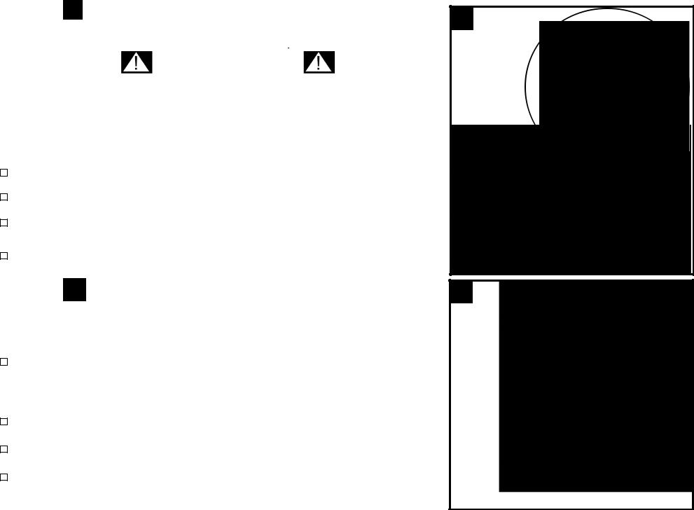
STEP 2
Install RO Drain Connector
|
|
|
|
WARNING |
|
CAUTION |
||
|
|
|
|
|
|
|
|
|
|
|
|
|
Be sure that all electrical appliances and outlets are turned off at the |
|
Please wear safety glasses to protect |
||
|
|
|
|
circuit breaker before working in cabinet area. |
|
eyes when drilling. |
||
|
|
|
|
|
|
|
|
|
Drain Connector Installation |
|
|
|
|
||||
Choose the drain outlet location. See Fig. 1 (page 3) |
|
|
|
|
||||
|
NOTE: Extra care should be taken when entering drains near dishwashers or food waste disposals, as backflow |
|||||||
|
may occur through the air gap and cause flooding. |
|
|
|
|
|||
1 |
Remove protective cover from back of Foam Seal |
|
. Knock out center hole and align holes then attach to Drain Connector |
|||||
|
||||||||
|
front plate |
|
. |
|
|
|
|
|
2Position the Drain Connector  on the sink drain pipe above the drain trap. Allow room for drilling. Tighten Screws
  and Nuts
  securely.
3Use a battery powered or properly grounded drill. Using the Drain Connector  port as a drill guide, drill a 7/32” hole through the wall of the drain pipe. Do NOT penetrate the opposite side of the pipe and be careful not to damage the side of the drain port fitting.
4If you wish to install your drain in a remote location refer to page 10.
STEP 3
Install RO Filter System Assembly
The Reverse Osmosis Filter System Assembly Head  is mounted on Mounting Screws
  .
.
The Mounting Screws  allow you to lift the RO Filter System Assembly without any hardware removal.
1Choose an easy-to-access area under the sink to mount the RO Filter System Head .
.
NOTE: To allow adequate space for filter changes, allow a minimum clearance of 4” - 6”below the filter to the floor. The Filter System Assembly must be mounted in a vertical position.
NOTE: Mount the Filter System Head to a solid cabinet wall or wall. If a solid surface is not available, use hollow-wall anchor bolts or toggle bolts (not included) to secure to the wall.
2Using the Built-in Bracket on the back of the RO System Head  , mark the holes for the Mounting Screws
  on the wall surface.
3Using a 1/8" drill bit, drill two pilot holes for the Mounting Screws . Insert Mounting Screws
  into the wall with a Phillips screwdriver, leaving approximately 3/8" of each Mounting Screw
  exposed.
4Hang the RO System Head  on the Mounting Screws
 .
.
2
N
M
K
L
L
3
A
|
|
|
C |
C |
10 ½” Minimum up from floor. This distance allows for space to change filters.
WFRO60X-1 |
5 |
|
|
V4.4 |
|
|
|

STEP 4
Install Water Storage Tank
Before you begin, check pressure in tank. Adjust to between 5 and 7 psi.
The Tank Ball Valve fitting on the Water Storage Tank may need to be tightened 3-4 turns to get a good seal. Do not over tighten.
TO INSTALL WATER STORAGE TANK:
1 Apply 2-3 wraps of Plumber’s Tape H to the threads on the nipple at the top of the Water Storage Tank E
2Locate the Tank Connector D . Hand tighten onto the Water Storage Tank E nipple 3-4 turns, being careful not to cross thread or over tighten.
3Do not connect the tube at this time. This will occur later in the assembly.
4Place the Water Storage Tank E next to the Reverse Osmosis Filter System Assembly. The Water Storage Tank E can be placed upright or on its side. Use provided mount stand.
STEP 5
Install RO Faucet
SELECT LOCATION OF REVERSE OSMOSIS FAUCET MOUNTING HOLE
You will need to select the location of the Reverse Osmosis Faucet P . You have three options to choose from:
Use an existing sink top hole. This may be blank. This is for the spray hose or soap dispenser (Must be between 1-3/8” and 1-5/8” in diameter)
Drill a new hole in the sink
Drill a new hole in the countertop next to the sink
1Determine where you are going to install your RO Faucet Body P .
2Check to ensure the RO Faucet Body P will mount flat against the mounting surface.
3Visually review the routing of the tubes from the RO System Head A to the RO Faucet Body P . Check to ensure there is adequate tube routing space between the RO Faucet Body P and RO System Head A .
4If drilling is needed, drill a 1-3/8" diameter hole in the mounting surface.
IMPORTANT: Drilling holes into countertops and sinks should only be performed by a quali ed installer who is certi ed for drilling such materials. Drilling of surfaces made of stone or solid surface materials such as granite, marble, Corian™ or other plastic resin products or sinks made of porcelain and stainless steel may cause permanent, irreparable damage to the sink or countertop surface.
4
D
E
YOU WILL NEED AN ACCURATE DIGITAL AIR PRESSURE GAUGE
5 |
P |
A |
WFRO60X-1 |
6 |
V4.4 |
STEP 6
Install RO Faucet (continued)
INSTALL REVERSE OSMOSIS FAUCET
1Locate and organize your RO Faucet install parts. See packing list on page 1.
2Attach  to RO Faucet Body.
3Route the 3 tubes  ,
, ,
, , attached to the RO Faucet Body
  through the RO Faucet Base
 , but don’t connect the
RO Faucet Body  to the RO Faucet Base
  yet. Then route the 3 tubes
  ,
, ,
, , through the hole in the sink until 12” of tubing remains above the sink. Lay RO Faucet Body
  on the counter top.
4Mount Faucet Body  to the sink hole by pushing the toggle bolts through the hole until the RO Faucet Body
  is flat against the sink surface. Position the toggle bolts to catch under the lower surface of the sink or counter, but ensure that they will not
obstruct the faucet stem from sitting in place. Loosely tighten the toggle bolts until the RO Faucet Base  is mounted loosely to the surface.
TIP: Make sure to keep the “wings” of the toggle bolts free to allow all tubing and faucet stem room
TIP: Install the faucet base with the bolts at 5 & 11 o’clock positions to have the handle positioned at 90 degrees to the right
5Hold the RO Faucet Base  firmly and mount the RO Faucet Body
  to the RO Faucet Base
  by turning 1/4 clockwise to lock. Ensure the RO Faucet Body Handle is positioned to your liking.
TIP: If there is not enough clearance for the tubing and the stem, the toggle wings may need to be adjusted to create more clearance.
6Turn the RO Faucet Body  1/4 turn counter-clockwise and remove the faucet enough to tighten the RO Faucet Base
  toggle bolt screws firmly. Do not over-tighten.
7 |
Mount the RO Faucet Body |
|
|
to the RO Faucet Base |
|
|
and turn 1/4 turn clockwise until it locks. |
||
|
|
|
|
||||||
8 |
Mount the RO Faucet Spout |
|
|
to the RO Faucet Body |
|
|
by screwing spout nut to body. |
||
|
|
|
|
||||||
6 |
O |
Q |
|
Mounting Surface |
|
|
P |
R |
1/4” Red Tube |
S |
3/8” White Tube |
T |
3/8” Red Tube |
WFRO60X-1 |
7 |
V4.4 |
STEP 7
Connect Tubing
Install 1/4" Plastic Tubing for Water Supply Line from Kitchen Faucet Adapter to System Head Inlet
1Determine the length of the 1/4" White Plastic Tubing  that will be necessary to connect the RO System Head
  Inlet (labeled “INLET”)
to the Kitchen Faucet Adapter  . Make sure to allow enough Plastic Tubing to prevent kinking in the line. Do not discard the remaining tubing for it will be used in Step 7.
2Cut the 6’-1/4" White Plastic Tubing  squarely on both ends with a utility knife, making sure not to crimp the Plastic Tubing during cutting.
3Wet one end of the 6’-1/4" White Plastic Tubing  with water and push it into the Kitchen Faucet Adapter
  approximately 5/8" until it stops.
NOTE: Do not bend or crimp 6-1/4" White Plastic Tubing when inserting.
4Wet the other end of the 6’-1/4" Clear Plastic Tubing  with water and push it into the RO System Head
  Inlet approximately 5/8" until it stops.
NOTE: The 1/4" Plastic Tubing does not need to be disconnected for general routine maintenance and filter replacement. However, Plastic Tubing may be easily disconnected if necessary. Simply turn off the water supply to the Filter System and press in the white collar around the fitting while pulling the Plastic Tubing out with the other hand
Install 3/8" Plastic Tubing for Water Supply Line from
System Head Outlet to RO Faucet
5Locate the 3/8" White Plastic Tubing  (see page 7 Step 2) attached to RO Faucet Body
  (see page 7 illustration).
6Determine the length necessary to connect to the RO System Head  Outlet (labeled “FAUCET”).
7Cut the tubing squarely with sharp utility or exacto knife.
8Wet the end of the 3/8" White Plastic Tubing  with water and push it into the RO System Head
  Outlet (labeled “FAUCET”) approximately 5/8”, until it stops.
7
3
F
4 |
A |
|
U
A
8
S
WFRO60X-1 |
8 |
V4.4 |

STEP 8
Connect Tubing (Continued)
AIR GAP FROM FAUCET TO RO ASSEMBLY
1 A |
Locate 1/4" Red Plastic Tubing |
|
|
|
already attached to the air gap barb on the |
|||||||||||||||||||||||||
|
R |
|||||||||||||||||||||||||||||
|
RO Faucet Body |
P |
. |
|
|
|
|
|
|
|
|
|
|
|
|
|
|
|
|
|
|
|
|
|
|
|
|
|||
|
Determine length necessary to connect to the drain outlet on the RO Membrane Filter |
|
. |
|||||||||||||||||||||||||||
2 A |
B2 |
|||||||||||||||||||||||||||||
3 A |
Cut 1/4" Red Plastic Tubing |
|
|
|
square and to length with sharp utility or exacto knife. |
|||||||||||||||||||||||||
R |
||||||||||||||||||||||||||||||
4 A |
Insert Restrictor |
|
into end of 1/4" Red Plastic Tubing |
|
. |
|
|
|
|
|
|
|||||||||||||||||||
I |
R |
|||||||||||||||||||||||||||||
|
NOTE: SYSTEM WILL NOT OPERATE WITHOUT RESTRICTOR. |
|||||||||||||||||||||||||||||
5 A |
Remove black plug from RO Membrane Filter |
|
drain port by pushing on white collar while |
|||||||||||||||||||||||||||
B2 |
||||||||||||||||||||||||||||||
|
pulling plug with other hand. Discard plug. |
|
|
|
|
|
|
|
|
|
|
|||||||||||||||||||
6 A |
Insert 1/4" Red Plastic Tubing |
|
|
all the way into the fitting on bottom of RO Membrane |
||||||||||||||||||||||||||
R |
||||||||||||||||||||||||||||||
|
Filter |
|
approximately 5/8” until it stops. |
|||||||||||||||||||||||||||
|
B2 |
|||||||||||||||||||||||||||||
7 A |
Pull on the 1/4" Red Plastic Tubing |
|
|
to be sure it is held firmly in the fitting. |
||||||||||||||||||||||||||
R |
||||||||||||||||||||||||||||||
CONNECT 3/8” RED TUBE FROM REVERSE OSMOSIS FAUCET TO DRAIN ADAPTER |
||||||||||||||||||||||||||||||
1 B |
Locate the 3/8” Red Plastic Tubing |
|
already attached to the RO Faucet Body |
|
. |
|||||||||||||||||||||||||
T |
P |
|||||||||||||||||||||||||||||
2 B |
The other end needs to be attached to the collet on the sink Drain Connector |
|
. |
|||||||||||||||||||||||||||
K |
||||||||||||||||||||||||||||||
3 B |
Cut 3/8” Red Plastic Tubing |
|
as needed to route in as straight of a run as possible, |
|||||||||||||||||||||||||||
T |
||||||||||||||||||||||||||||||
|
without loops, dips, low spots, |
or kinks. |
||||||||||||||||||||||||||||
4 B |
Cut the end of the 3/8” Red Plastic Tubing |
|
square with a sharp utility or exacto knife. |
|||||||||||||||||||||||||||
T |
||||||||||||||||||||||||||||||
5 B Insert all the way into the fitting approximately 1” until it stops. |
||||||||||||||||||||||||||||||
6 B |
Pull on the tube to be sure it is held firmly in the fitting. |
|||||||||||||||||||||||||||||
CONNECT TUBING FROM RO SYSTEM HEAD TO WATER STORAGE TANK
1 C Use the remaining 3/8” White Tubing U from Step 6 and determine length necessary to connect the Tank outlet (labeled “TANK”) on RO System Head A to the
Water Storage Tank E .
2 
 C Cut 3/8" White Plastic Tubing U square with a sharp utility or exacto knife.
3 
 C Wet the end of tubing and Insert into compression nut of Tank Connector D fitting. Which was connect to tank previously.
4 
 C Tighten compression nut to secure tubing to Tank Connector D .
5 
 C Insert the other end of 3/8" White Plastic Tubing U into the outlet of the RO System Head A (labeled “TANK”) approximatley 5/8” until it stops.
NOTE: Tubing lengths should allow for the removal of the assembly from the mount screws for servic ing. If tubing lengths are shortened for neater appearance, it may be necessary to keep the assembly on the mount sc rews for servic e.
NOTE: Codes in the state of Massac husetts require installation by a lic ensed plumber and do not permit the use of saddle valves. If you live in the state of Massac husetts, review plumbing c ode 248-CMR of the Commonwealth of Massachusetts before proc eeding with the installation.
8 |
|
|
|
|
|
|
|
|
P |
|
|
|
S |
|
|
|
|
T |
|
F |
|
K |
A |
D |
|
|
|
U |
|
|
|
|
|
|
|
|
|
B2 |
|
|
U |
|
|
E |
|
R |
|
|
|
|
|
|
|
|
|
|
I |
|
|
|
|
4 A |
|
|
|
|
|
B2 |
B2 |
6 A
5 
 A
A
|
|
|
R |
R |
|
|
|
|
|
|
|
|
|
|
|
|
|
|
|
|
|
|
|
|
|
|
|
|
4 C |
D |
|
|
|
|
|
|
|
|
A |
|
|
|||||
|
|
|
|
|
|
|
|
|
|
|
|||
|
|
|
|
|
|
|
|
|
|
|
|
|
|
|
|
3 C |
|
|
|
|
|
|
|
|
|
|
|
|
|
|
|
|
|
|
|
U |
|
|
|
||
|
A |
|
|
|
|
|
|
|
|
||||
|
|
|
|
|
|
|
|
|
|
|
|
|
|
|
|
|
|
|
|
|
|
|
|
|
|
|
|
|
|
|
U |
|
|
|
|
|
|
|
|
|
|
|
|
|
|
|
|
|
|
|
|
|
|
|
|
|
|
|
|
|
|
|
|
|
|
|
|
|
|
WFRO60X-1 |
9 |
V4.4 |
|
STEP 9
Install RO System and Drain In Remote Location
INSTALL A REMOTE DRAIN POINT AND AIR GAP (Remote Location)
You can also run the drain tubing to an existing drain in the house. A floor drain, laundry tub, standpipe, sump, etc. are suitable drain points. This type of drain is preferred over the drain connector. Check your local codes. Longer lengths of tubing (see parts list in manual) may be needed.
Always be sure to provide an air gap between the end of the hose and the drain point. This will prevent water from backing up into the system. Air gaps are required code in most areas.
TO INSTALL A REMOTE DRAIN POINT, COMPLETE THE FOLLOWING STEPS:
1Remove the 1/4" Red Plastic Tubing R from the RO Faucet Body P by pulling gently.
2Determine if this length is long enough to reach the drain point. If it is, then insert Restrictor I in end of tubing and then insert this end of tubing into drain port on RO Membrane Filter B2 .
3If not, replace the 1/4" Red Plastic Tubing R with an adequate length of tubing to reach the drain point. Then insert Restrictor I in end of tubing and then insert this end of tubing into drain port on RO Membrane Filter B2 . Refer to Step 6 in manual on how to disconnect and connect tubing.
4Run the tubing to the drain point and secure at the end with a bracket (purchased locally). Provide a 1-1/2” air gap between the end of the tube and the drain.
5Remove 3/8" White Plastic Tubing T from RO Faucet Body P and discard.
6Faucet will not have 1/4” or 3/8” tubing attached to the airgap barbs in the RO Faucet Body P for remote installation.
9 |
WFRO60X-1 |
10 |
V4.4 |

STEP |
10 |
10 |
|
Sanitize, Test and Purge System |
G |
||
SANITIZE THE SYSTEM |
|||
Sanitizing is recommended immediately after installation of the RO Filter System Assembly. It’s also recommended after servicing inner |
|
||
parts. It is important that the person installing or servicing the system have clean hands while handling inner parts of the system. |
A |
||
Complete the following steps to sanitize the system. |
|||
D |
|||
|
|
||
1 Make sure the water supply to the RO Filter System Assembly is off. |
U |
||
2Open the Reverse Osmosis Faucet. If the Water Storage Tank is not already empty, allow the water to completely empty.
3Find the eyedropper G included in package and common household bleach (5.25%).
4 |
Disconnect the 3/8” White Plastic Tubing |
|
from the Water Storage Tank |
|
by unscrewing the nut from the Tank Connector |
|
fitting. |
U |
E |
D |
5Add 3 ml. of bleach into the open end of Water Storage Tank E 3/8”White Plastic Tubing S . Handle bleach according to manufacturer’s instructions.
6 |
Re-connect Water Storage Tank and 3/8”White Plastic Tubing |
|
to Tank Connector |
|
fitting. |
|
|
S |
D |
|
|||||
E |
|||||||
7 |
Sanitizing the RO Filter System Assembly will be completed during the pressure test and purging following steps below. |
||||||
|
|||||||
NOTE: The bleach must be completely removed from the system before drinking the RO water. See purging instructions below.
PRESSURE TEST THE SYSTEM
IMPORTANT: Complete the sanitizing procedures above before pressure testing.
1Open the cold water supply valve to the RO Filter System Assembly. See page 3, Fig. 1
2Open the kitchen faucet. This will purge air from the plumbing system. Close kitchen faucet when water runs smooth.
3Ensure RO Faucet is closed.
4Pressure will start to build in the RO Filter System Assembly in about 2 hours. Carefully inspect all fittings and connections while the RO Filter System Assembly builds pressure. Check for leaks and fix if any are found by ensuring all tubing is cut square and fully inserted. Also ensure tubing doesn’t have a scratch, dent, or notch at the end. If so, cut 1” off squarely and re-insert. If problems exist, refer to the troubleshooting chart or call the toll free number.
NOTE: When the RO Filter System Assembly is first pressurized, water may “discharge” from the faucet air gap hole until air is passed from the
RO Filter System Assembly.
PURGING THE SYSTEM
1Open the Reverse Osmosis Faucet and let water flow through the system for a 24 hour period. Water will flow heavily until tank becomes empty, and then it will be a slow drip for the balance of 24 hours.
NOTE: The flow rate will be very slow during the purge.
2
3
Close the Reverse Osmosis faucet after the 24 hour purge is complete. Your Reverse Osmosis system is ready for use when the purge is complete.
Review the following operating features before using your Reverse Osmosis System:
You will not have filtered water immediately. It will take 1-3 hours to completely fill the storage tank to create liberal flow from the faucet. The flow rate from the Reverse Osmosis system will be less than your kitchen faucet. Water will run to the drain while the Reverse Osmosis is filtering water, even when you are not using it. You may hear a water going to the drain – this is normal. Water going to the drain will automatically stop when the storage tank is at capacity.
THAN K YOU FOR YOUR BUSIN ESS!
WFRO60X-1 |
11 |
V4.4 |
 Loading...