

Page 1
Installation
Instructions
Reverse Osmosis Drinking Water Filtration System
Instrucciones de instalación
Sistema de filtración de agua potable por ósmosis inversa
Water Filtration
Model Series WFRO60X-1
Serie del modelo WFRO60X-1
V4.4
Page 2
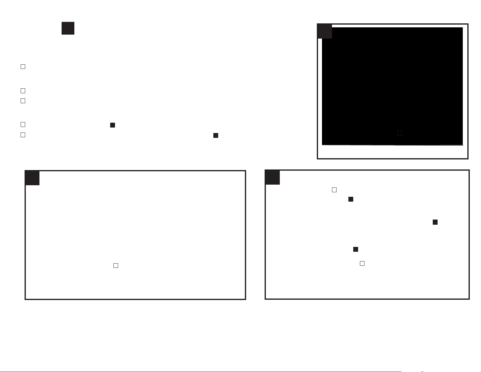
Package Contents
Installation Instructions
Reverse Osmosis Drinking Water
Filtration System
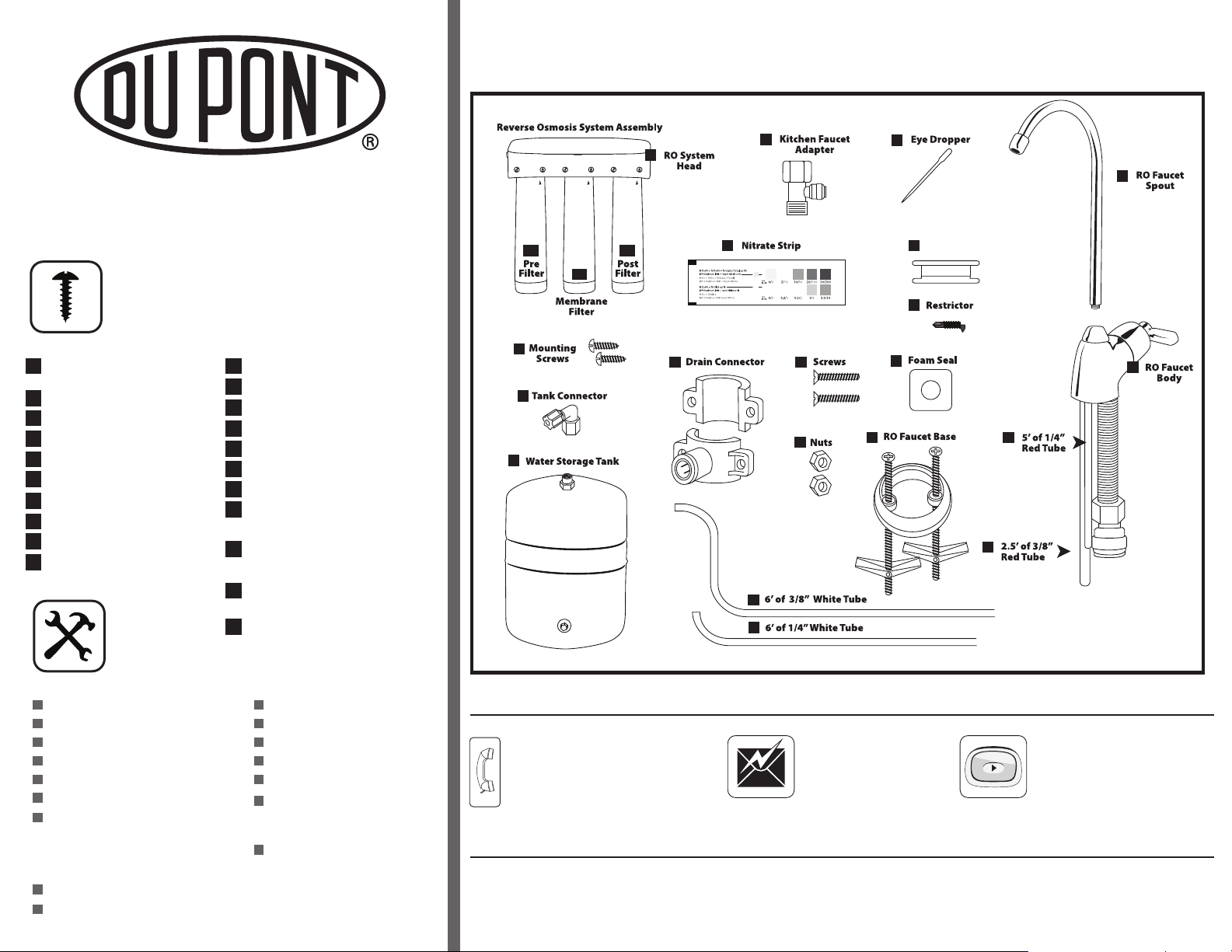
Parts & Hardware Included
RO Filter System Head with
A
Built-in Bracket
B QuickTwist
™
Filters
C Mounting Screws
D Tank Connector
E Water Storage Tank
F Kitchen Faucet Adapter
G Eye Dropper
H Plumber’s Tape
I Restrictor
J Nitrate Test Strip
K
Drain Connector
L
Drain Connector Screws
Nuts
M
Foam Seal
N
RO Faucet Spout
O
RO Faucet Body
P
RO Faucet Base
Q
R 5’ of 1/4” Red Tube
(RO Faucet Body to RO Membrane Filter)
6’ of 3/8” White Tube
S
(RO Faucet Body to RO System Head)
2.5’ of 3/8” Red Tube
T
(RO Faucet Body to Drain Connector)
6’ of 1/4” White Tube
U
(Kitchen Faucet Adapter to
RO System Head)
A
B1
B2
C
D
E
B3
K
F
J
L
M
S
U
G
O
H
Plumber’s Tape
I
N
Q
R
T
P
To ols & Materials Required
Phillips Screwdriver
1/8" Drill Bit
Center Punch
Adjustable Wrench
Utility Knife
File
Tape Measure
Optional Materials
Drill with 1/4" & 9/16" or 5/8" Drill Bits
Hollow-Wall Anchor Bolts or Toggle Bolts
Safety Glasses
Masking Tape
Newspaper or Towels
Pencil
Pan or Bucket
Compression Cap (OptionalFor Kitchen Faucet Spray
Hose Connector)
Digital Air Pressure Gauge
Information & Assistance
For Service Requests & Product Information
Hours of Operation: 24 Hours/Day, 7 Days/Week
800-441-7515
For Safety & Health Questions
For installations in Massachusetts, the Commonwealth of Massachusetts Plumbing Code CMR248 shall be adhered to. Codes in the state of Massachusetts require
installation by a licensed plumber and do not permit the use of saddle valves.
Toll Free866-709-2086
email us at:
waterfiltration@mail1.dupont.com
Protect Plus, LLC 420 Third Avenue NW Hickory, NC 28601
‘How to Install’ Video FREE Download
www.waterfiltration.dupont.com
Page 3
DuPont™Water Filtration would like to thank you for your recent purchase of the DuPont™Reverse
Osmosis Filtration System.
We greatly appreciate your business and the opportunity to assist you. Your satisfaction is the greatest importance to us. We hope that you will inform
us if there is ever anything we can do to improve our products. Please contact us if you have any questions or if there is anything we can do to assist
you with your new product.
Reverse Osmosis, also known as hyper filtration, is the most com
substantially
are 0.2 to 1 micron & viruses are 0.025 to 0.4 microns).
reducing a very wide array of contaminants. The pores in a reverse osmosis membrane are approximately 0.025 micron in size (bacteria
mon treatment technology used by premium bottled water companies. It is effective in
How Reverse Osmosis works –
Your new Reverse Osmosis (RO) system is composed of a 3-stage system manifold, a 3000 series pre-filter, the reverse osmosis membrane, a storage
tank, a 3000 series post-filter and a faucet to deliver the filtered water to your countertop. First the water goes to the pre-filter, which is a replaceable
cartridge that reduces chlorine, odor, sand, silt, dirt, and other sediments to improve the taste of your water. Next, the water flows to the Reverse
Osmosis
into the storage tank. A diaphragm inside the tank keeps the water pressurized to about 30 psi when the tank is full. This is what provides the fast flow
to the faucet. When the tank is empty, it
final
Your system also has an automatic shutoff valve to conserve water. When the storage tank is full and the faucet is not open, pressur
valve
system drops and the shutoff valve opens to allow the tank to be re-filled.
Reverse Osmosis uses a membrane that is semi-permeable, allowing cleaner water to pass through it, while rejecting the contaminants that are too
large to pass through the tiny pores in the membrane. This quality reverse osmosis system uses a process known as cross-flow to allow the membrane
to
away from the membrane and down the drain. The process of reverse osmosis requires a driving force to push the water through the membrane - the
pressure provided by your home’s water supply is sufficient: 40 to 100 psi.
cartridge, which is a tightly wound membrane that reduces the total dissolved solids and organic matter. The water goes from the membrane
filter. This is a replaceable cartridge that reduces any remaining tastes and odors to provide cleaner great tasting drinking water to the faucet.
to stop flow of water with contaminants to the drain. After enough drinking water is drawn from the faucet, the pressure in the Reverse Osmosis
continually clean itself. As some of the fluid passes through the membrane the rest continues downstream, sweeping the rejected contaminants
should be pressurized to 5 – 7 psi. As water is drawn to the faucet, it flows from the storage tank through the
e closes the shutoff
What it removes –
Your Reverse Osmosis (RO) unit will reduce Chlorine, Odor, Particulates, Sediment, and improve taste, according to NSF 42 standards. It will also
reduce Total Dissolved Solids (TDS), Pentavalent Arsenic, Hexavalent Chromium, Lead, Cadmium, Cysts, Nitrate Plus Nitrite, Nitrate, & Nitrite according
to NSF 58 standards.
Thanks again for your purchase
~ The DuPont Water Filtration Team
CAUTION CAUTION
This filter must be protected from
freezing, which can cause cracking
of the filter and water leakage.
Because of the product’s limited service life and to prevent costly repairs or possible water damage, we
strongly recommend that the housing be replaced every five years. If the head of the filter has been in use
for longer than this period, it should be replaced immediately. Date the top of any new head to indicate the
next recommended replacement date.
Page 4
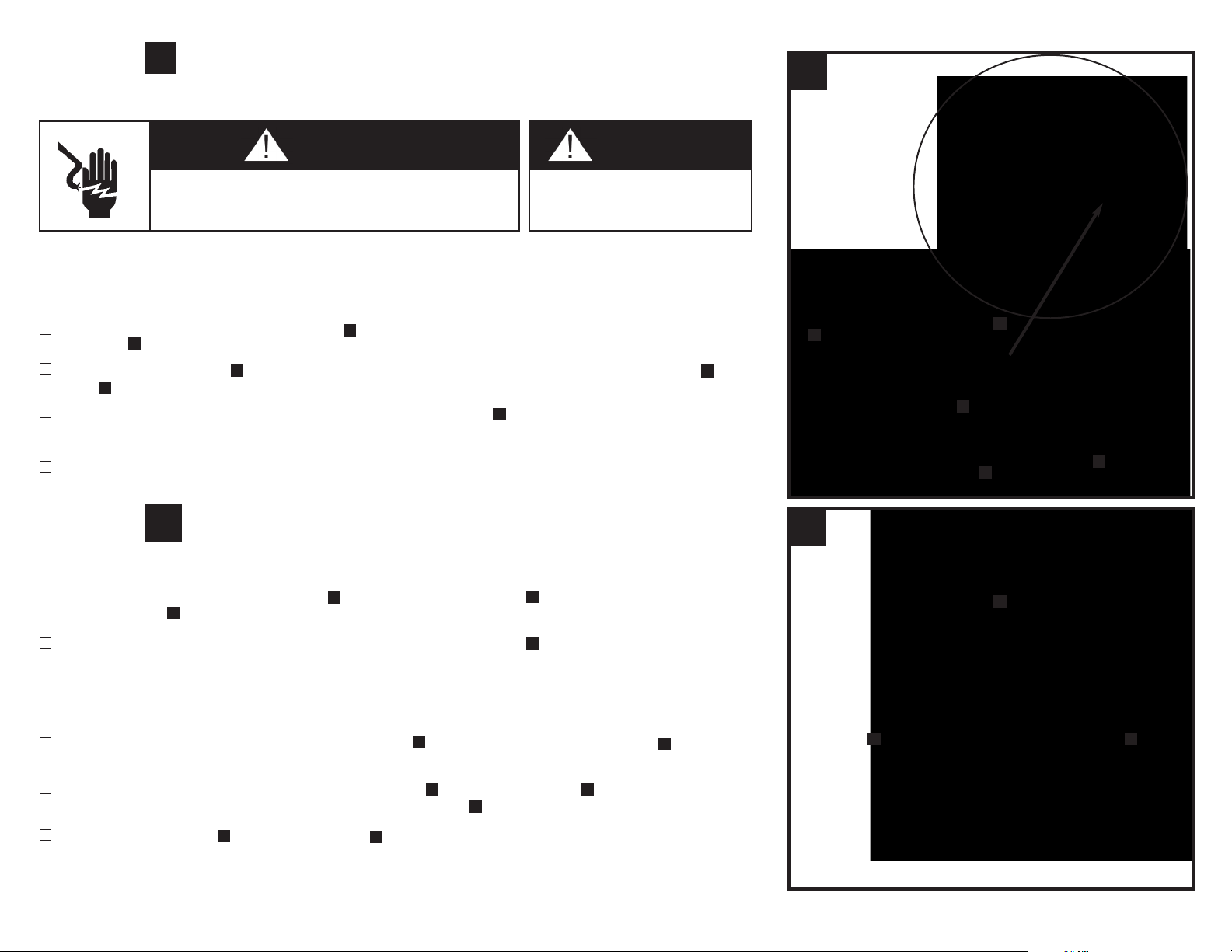
Plan Your Installation
It is recommended to read through the entire manual before beginning your installation.
Follow all steps exactly. Reading this manual will also help you get all the benefits
from your system.
Your Reverse Osmosis Drinking Water System can be installed under a sink or in a
remote location. Typical remote sites are a basement or laundry room or utility room. Review
the location options below and determine where you are going to install your system.
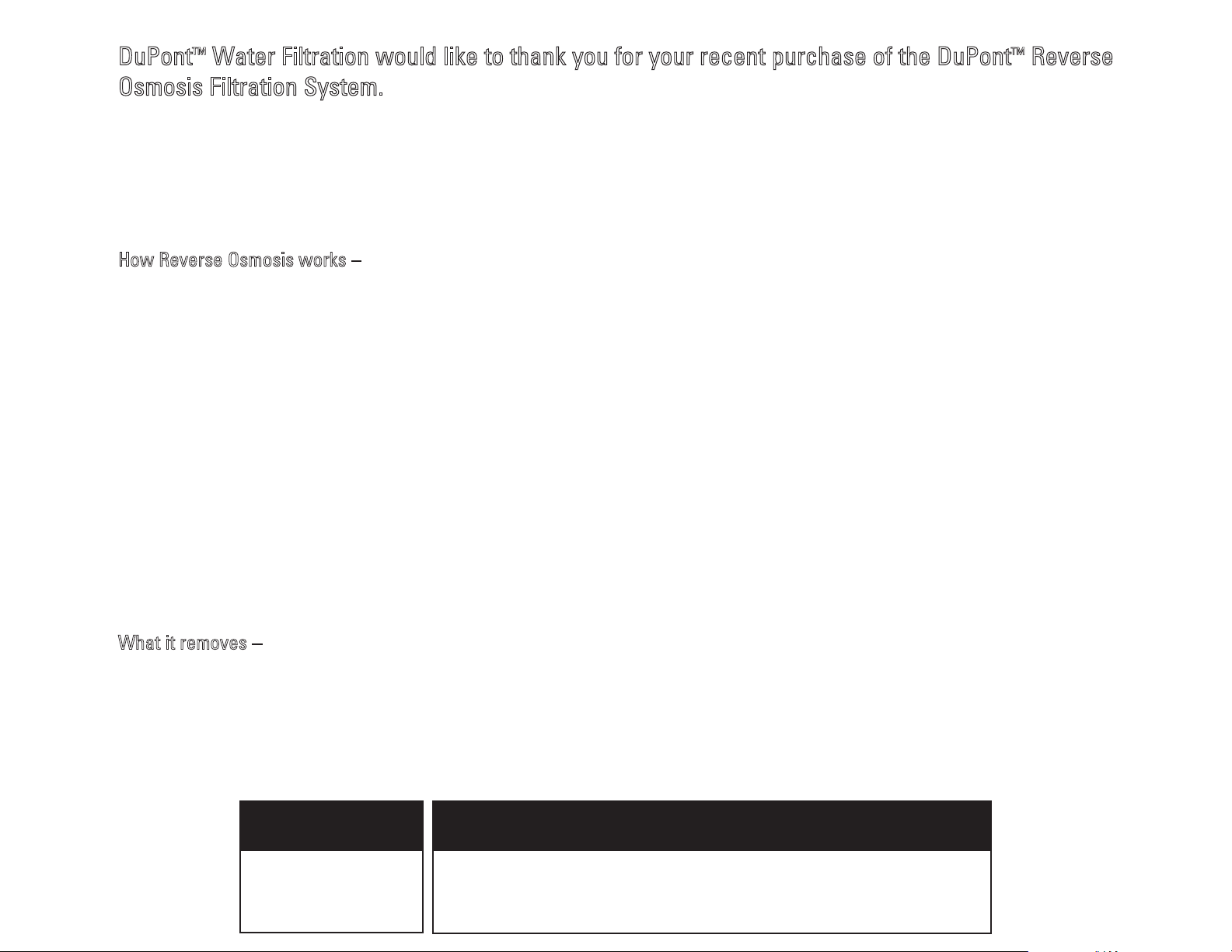
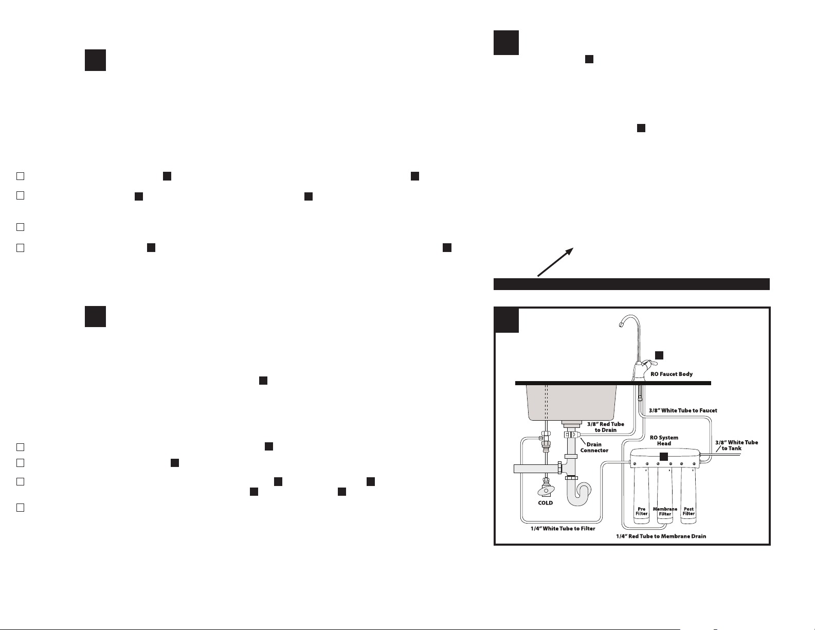
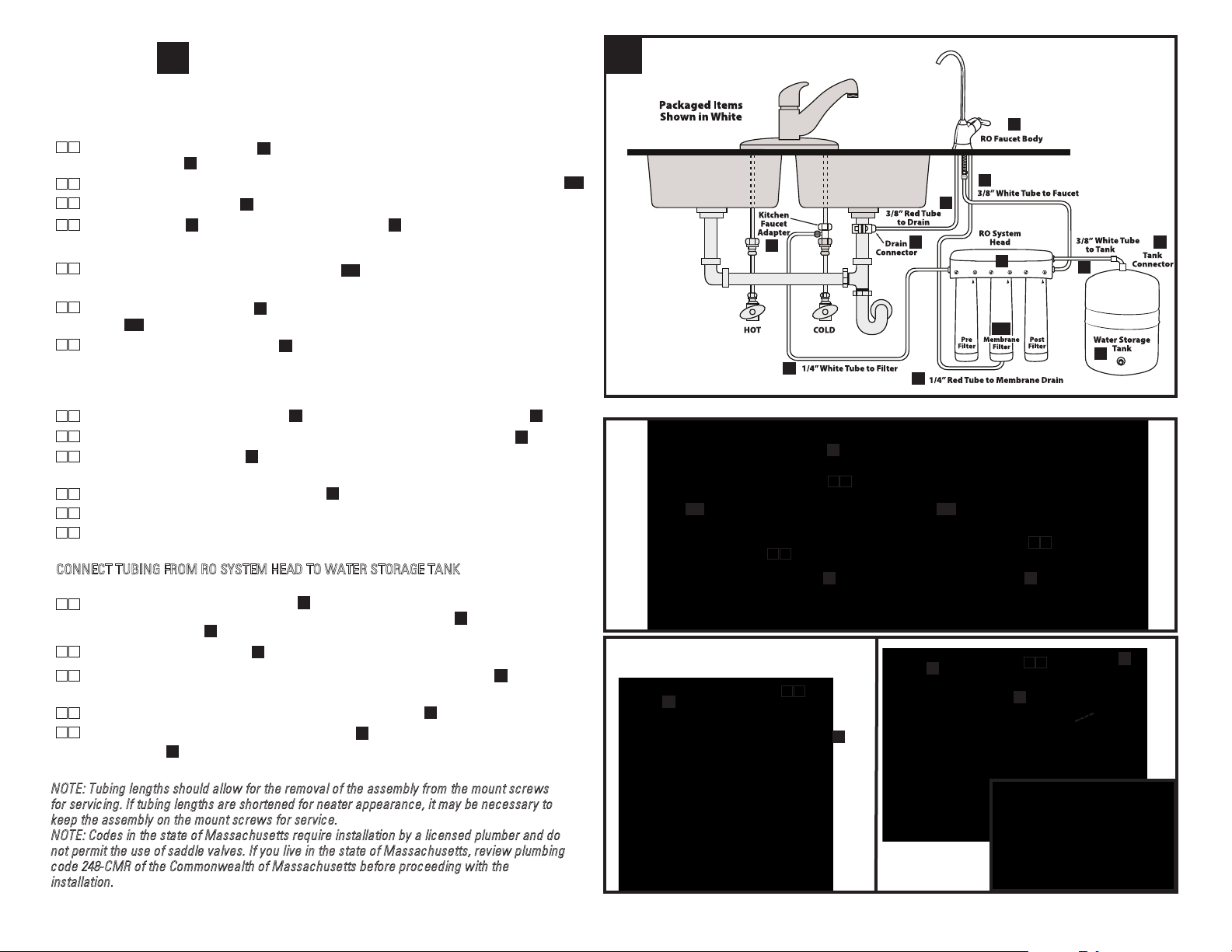
Under The Sink Location
The Reverse Osmosis Filter Assembly and storage tank are normally installed in a
kitchen or bathroom sink cabinet. See Fig. 1.
A suitable drain point is needed for reject water from the Reverse Osmosis Filter.
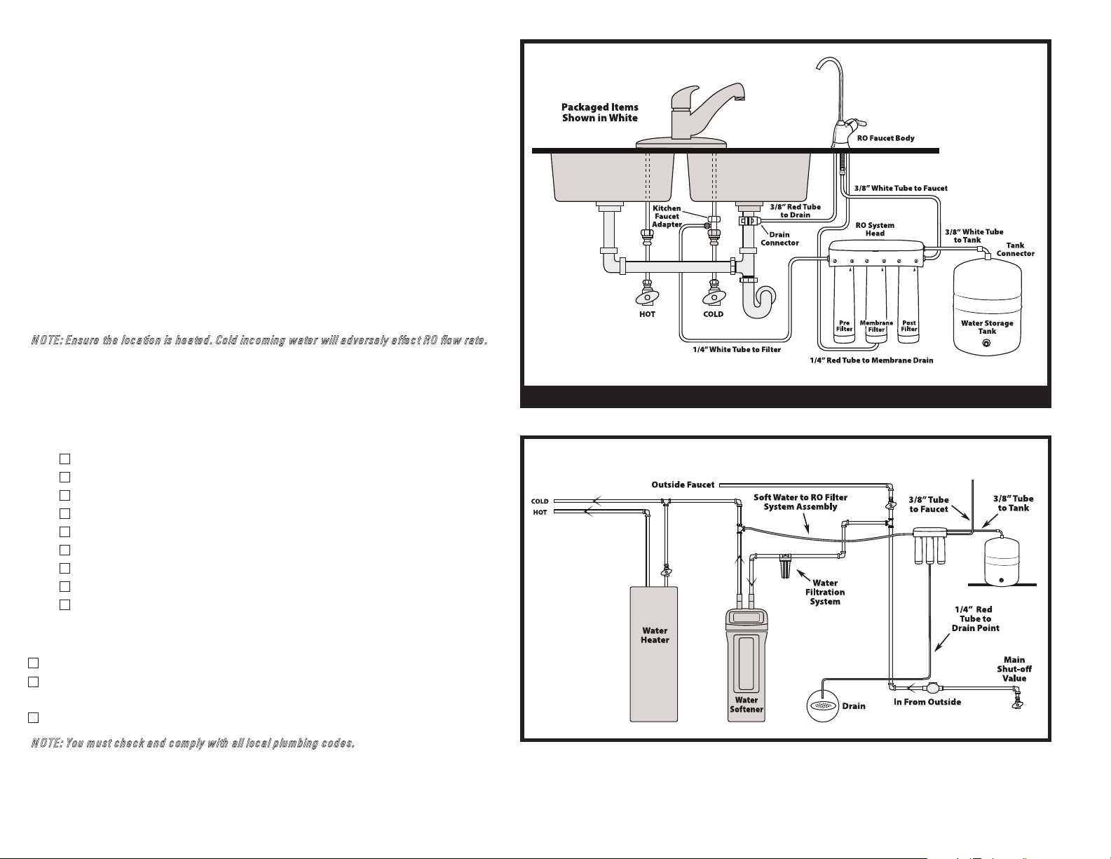
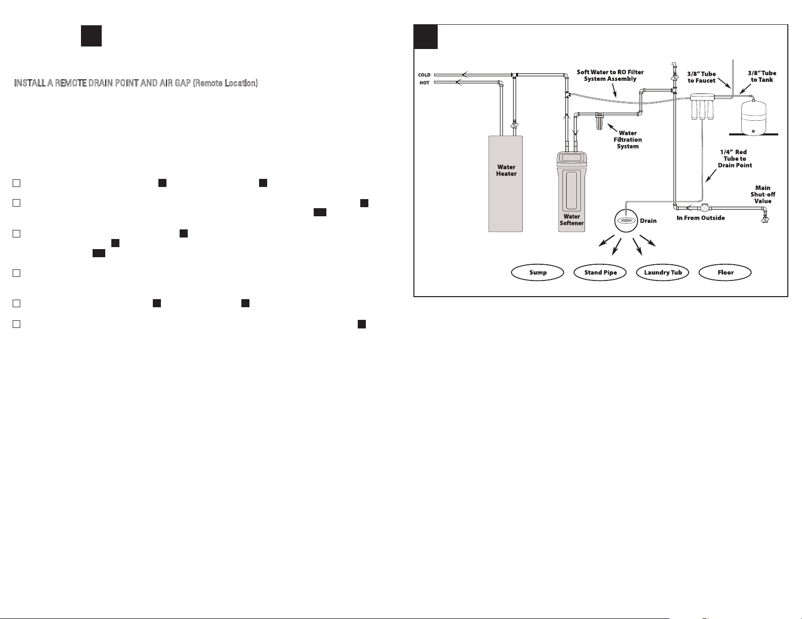
Remote Location
You can also locate the Reverse Osmosis Filter Assembly and storage tank in a remote
location away from the Reverse Osmosis Faucet. You will need a nearby water
source and drain point. See Fig. 2.
OTE: E nsu re the loc atio n is h e ated. Co ld incomin g w ater w ill a d verse ly affec t RO flo w rate .
N
Check Space Requirements
Check size and position of items for proper installation into location chosen.
Overview and Site Preparation
There are seven easy steps to installing your Drinking Water system. They are as follows:
1
STEP - Install Kitchen Faucet Adapter
2
STEP - Install RO Drain Connector
3
STEP - Install RO Filter Assembly
4
STEP - Install Water Storage Tank
5
STEP - Install RO Faucet
6
STEP - Connect Tubing
7
STEP - Connect Tubing Continued
8
STEP - Install RO System and Drain in Remote Location
9
STEP - Sanitize, Pressure Test, Purge System
for Water Supply Line from Kitchen Faucet Adapter to RO System Head
Fig. 1Fig. 1
NOTE: DO NOT CONNECT 3/8” RED DRAIN TUBING TO DRAIN WITH A GARBAGE DISPOSAL.
Fig. 2
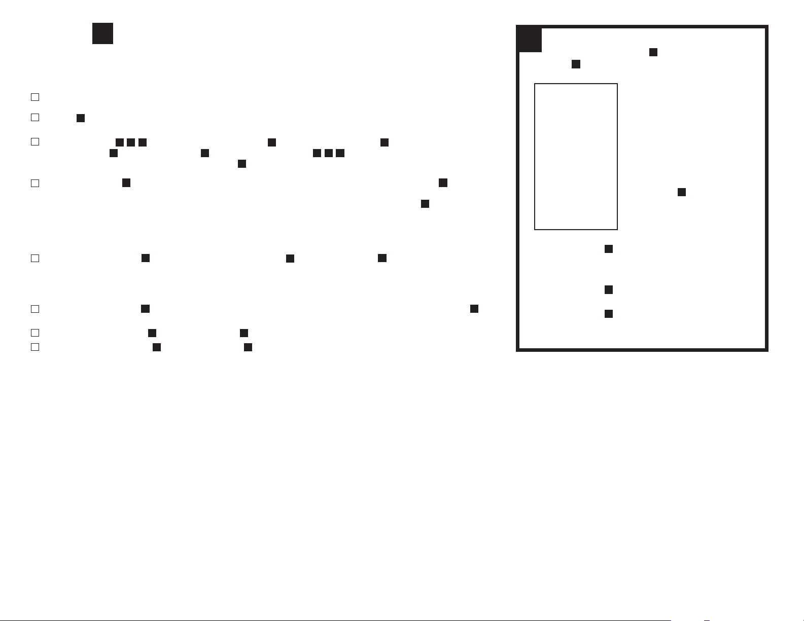
Prepare Site For Installation
1
Before starting, close the cold water shut-off valves.
2
Temporarily place tank and filter assembly into cabinet. Double check position of
items and space required for proper installation.
3
Remove tank and filter from cabinet and set aside.
OTE: Y ou must ch ec k and c omply w ith a ll lo c al p lum bin g c o d e s.
N
WFRO60X-1
3
V4.4
Page 5
STEP
1
Install Kitchen Faucet Adapter
CHOOSE TYPE OF WATER FITTING TO INSTALL
1
Locate the cold water line in the sink cabinet. Turn off the cold water supply to the sink.
NOTE: If uncertain about which line supplies the cold water, turn on the hot water to the faucet. Allow the water to heat up and carefully
feel the pipes under the sink. The pipe that remains cool to the touch is the cold water supply.
2
Turn on the kitchen faucet to release pressure and allow water to completely drain from the line.
3
Disconnect the cold water line from the 1/2" threaded stem on the bottom of the kitchen faucet.
NOTE: If rigid plumbing pipe (metal or plastic) is used, you may need to shorten the supply pipe using a hacksaw or pipe cutter to
accommodate the Kitchen Faucet Adapter.
4
Holding the Kitchen Faucet Adapter in an upright position (see diagram), screw onto the threaded faucet stem.
5
Screw the cold water supply line to the male threads of the Kitchen Faucet Adapter using the nut that was connecting the cold
water line to the kitchen faucet previously. For a secure fit, tighten the nut using an adjustable wrench.
F
F
1
1
1
RIGID WATER LINES
1
4
F
F
F
3
5
FLEX HOSE WATER LINES
WFRO60X-1
4
V4.4
Page 6
STEP
2
Install RO Drain Connector
WARNING CAUTION
2
Be sure that all electrical appliances and outlets are turned off at the
circuit breaker before working in cabinet area.
Drain Connector Installation
Choose the drain outlet location. See Fig. 1 (page 3)
NOTE: Extra care should be taken when entering drains near dishwashers or food waste disposals, as backflow
may occur through the air gap and cause flooding.
1
Remove protective cover from back of Foam Seal Knock out center hole and align holes then attach to Drain Connector
front plate .
2
Position the Drain Connector on the sink drain pipe above the drain trap. Allow room for drilling. Tighten Screws and
Nuts securely.
3
Use a battery powered or properly grounded drill. Using the Drain Connector port as a drill guide, drill a 7/32” hole through
the wall of the drain pipe. Do NOT penetrate the opposite side of the pipe and be careful not to damage the side of the drain
port fitting.
4
If you wish to install your drain in a remote location refer to page 10.
STEP
K
K
M
3
N
.
K
Please wear safety glasses to protect
eyes when drilling.
Install RO Filter System Assembly
The Reverse Osmosis Filter System Assembly Head is mounted on Mounting Screws .
The Mounting Screws allow you to lift the RO Filter System Assembly without any hardware removal.
C
A
C
M
L
N
K
L
L
3
A
1
Choose an easy-to-access area under the sink to mount the RO Filter System Head .
OTE: To allow adequate space for filter changes, allow a minimum clearance of 4” - 6”below the filter
N
The Filter System Assembly must be mounted in a vertical position.
NOTE: Mount the Filter System Head to a solid cabinet wall or wall. If a solid surface is not available, use hollow-wall
anchor bolts or toggle bolts (not included) to secure to the wall.
2
Using the Built-in Bracket on the back of the RO System Head , mark the holes for the Mounting Screws on the
wall surface.
3
Using a 1/8" drill bit, drill two pilot holes for the Mounting Screws . Insert Mounting Screws into the wall with a
Phillips screwdriver, leaving approximately 3/8" of each Mounting Screw exposed.
4
Hang the RO System Head on the Mounting Screws .
WFRO60X-1
A
A
C
C
C
A
C
5
to the floor.
C
C C
10 ½” Minimum up from floor. This distance allows for space to change filters.
V4.4
Page 7
STEP
4
Install Water Storage Tank
Before you begin, check pressure in tank. Adjust to between 5 and 7 psi.
4
D
The Tank Ball Valve fitting on the Water Storage Tank may need to be tightened 3-4 turns to get a good seal.
Do not over tighten.
TO INSTALL WATER STORAGE TANK:
1
Apply 2-3 wraps of Plumber’s Tape to the threads on the nipple at the top of the Water Storage Tank
2
Locate the Tank Connector . Hand tighten onto the Water Storage Tank nipple 3-4 turns, being careful not to
cross thread or over tighten.
3
Do not connect the tube at this time. This will occur later in the assembly.
4
Place the Water
be placed upright or on its side. Use provided mount stand.
STEP
Storage Tank next to the Reverse Osmosis Filter System Assembly. The Water Storage Tank can
5
H E
D E
E E
Install RO Faucet
SELECT LOCATION OF REVERSE OSMOSIS FAUCET MOUNTING HOLE
Y
ou will need to select the location of the Reverse Osmosis Faucet . You have three options to choose from:
Use an existing sink top hole. This may be blank. This is for the spray hose or soap dispenser
(Must be between 1-3/8” and 1-5/8” in diameter)
Drill a new hole in the sink
Drill a new hole in the countertop next to the sink
1
Determine where you are going to install your RO Faucet Body .
2
Check to ensure the RO Faucet Body will mount flat against the mounting surface.
P
P
P
E
YOU WILL NEED AN ACCURATE DIGITAL AIR PRESSURE GAUGE
5
P
A
3
Visually review the routing of the tubes from the RO System Head to the RO Faucet Body . Check to ensure there is
adequate tube routing space between the RO Faucet Body and RO System Head .
4
If drilling is needed, drill a 1-3/8" diameter hole in the mounting surface.
IMPORTANT: Drilling holes into countertops and sinks should only be performed by a qualied installer who is certied for drilling such materials.
Drilling of surfaces made of stone or solid surface materials such as granite, marble, Corian™ or other plastic resin products or sinks made of
porcelain and stainless steel may cause permanent, irreparable damage to the sink or countertop surface.
WFRO60X-1
A P
P A
6
V4.4
Page 8
STEP
6
Install RO Faucet (continued)
INSTALL REVERSE OSMOSIS FAUCET
1
Locate and organize your RO Faucet install parts. See packing list on page 1.
2
S
Attach to RO Faucet Body.
6
Q
Mounting Surface
O
3
Route the 3 tubes , attached to the RO Faucet Body through the RO Faucet Base , but don’t connect the
RO Faucet Body to the RO Faucet Base yet. Then route the 3 tubes through the hole in the sink until 12” of
tubing remains above the sink. Lay RO Faucet Body on the counter top.
4
Mount Faucet Body to the sink hole by pushing the toggle bolts through the hole until the RO Faucet Body is flat against
the sink surface. Position the toggle bolts to catch under the lower surface of the sink or counter, but ensure that they will not
obstruct the faucet stem from sitting in place. Loosely tighten the toggle bolts until the RO Faucet Base is mounted loosely to
the surface.
TIP: Make sure to keep the “wings” of the toggle bolts free to allow all tubing and faucet stem room
TIP: Instal
5
Hold the RO Faucet Base firmly and mount the RO Faucet Body to the RO Faucet Base by turning 1/4 clockwise to lock.
Ensure the RO Faucet Body Handle is positioned to your liking.
TIP: If there is not enough clearance for the tubing and the stem, the toggle wings may need to be adjusted to create more
clearance.
6
Turn the RO Faucet Body 1/4 turn counter-clockwise and remove the faucet enough to tighten the RO Faucet Base toggle
bolt screws firmly. Do not over-tighten.
7
Mount the RO Faucet Body to the RO Faucet Base and turn 1/4 turn clockwise until it locks.
8
Mount the RO Faucet Spout to the RO Faucet Body by screwing spout nut to body.
R,S,T P QP
P Q
P
P P
l the faucet base with the bolts at 5 & 11 o’clock positions to have the handle positioned at 90 degrees to the right
Q Q
P Q
P Q
PO
P
T
,R,S,
Q
1/4” Red Tube
R
S
3/8” White Tube
T
3/8” Red Tube
P
WFRO60X-1
7
V4.4
Page 9
STEP
7
Connect Tubing
Install 1/4" Plastic Tubing for Water Supply Line from Kitchen Faucet Adapter
to System Head Inlet
7
3
F
1
Determine the length of the 1/4" White Plastic Tubing that will be necessary to connect the RO System Head Inlet (labeled “INLET”)
to the Kitchen Faucet Adapter .Make sure to allow enough Plastic Tubing to prevent kinking in the line. Do not discard the remaining tubing
for it will be used in Step 7.
2
Cut the 6’-1/4" White Plastic Tubing squarely on both ends with a utility knife, making sure not to crimp the Plastic Tubing during cutting.
3
Wet one end of the 6’-1/4" White Plastic Tubing with water and push it into the Kitchen Faucet Adapter approximately 5/8" until it stops.
NOTE: Do not bend or crimp 6-1/4" White Plastic Tubing when inserting.
4
Wet the other end of the 6’-1/4" Clear Plastic Tubing with water and push it into the RO System Head Inlet approximately 5/8" until it stops.
NOTE: The 1/4" Plastic Tubing does not need to be disconnected for general routine maintenance and filter replacement. However,
Plastic Tubing may be easily disconnected if necessary. Simply turn off the water supply to the Filter System and press in the white collar
around the fitting while pulling the Plastic Tubing out with the other hand
F
U
U A
U F
U A
Install 3/8" Plastic Tubing for Water Supply Line from
System Head Outlet to RO Faucet
5
Locate the 3/8" White Plastic Tubing (s(see page 7 Step 2) attached to RO Faucet Body ee page 7 illustration).
6
Determine the length necessary to connect to the RO System Head Outlet (labeled “FAUCET”).
7
Cut the tubing squarely with sharp utility or exacto knife.
8
Wet the end of the 3 /8" White Plastic Tubing with wat
approximately 5/8”, until it stops.
S
A
S
er and push it into the RO System Head Outlet (labeled “FAUCET”)
P
A
4
U
A
A
8
S
WFRO60X-1
8
V4.4
Page 10
STEP
8
Connect Tubing (Continued)
AIR GAP FROM FAUCET TO RO ASSEMBLY
1 A
Locate 1/4" Red Plastic Tubing already attached to the air gap barb on the
RO Faucet Body .
2 A
Determine length necessary to connect to the drain outlet on the RO Membrane Filter .
3 A
Cut 1/4" Red Plastic Tubing square and to length with sharp utility or exacto knife.
4 A
I
nsert Restrictor into end of 1/4" Red Plastic Tubing .
NOTE: SYSTEM WILL NOT OPERATE WITHOUT RESTRICTOR.
5 A
Remove black plug fr
pulling plug with other hand. Discard plug.
6 A
Insert 1/4" Red Plastic Tubing all the way into the fitting on bottom of RO Membrane
B2
Filter approximately 5/8” until it stops.
7 A
Pull on the 1/4" Red Plastic Tubing to be sure it is held firmly in the fitting.
CONNECT 3/8” RED TUBE FROM REVERSE OSMOSIS FAUCET TO DRAIN ADAPTER
P
I
om RO Membrane Filter drain port by pushing on white collar while
R
R
R
B2
R
R
B2
8
P
S
T
F
U
K
A
B2
R
U
E
D
1 B
Locate the 3/8” Red Plastic Tubing already attached to the RO Faucet Body .
2 B
The other end needs to be attached to the collet on the sink Drain Connector .
3 B
Cut 3/8” Red Plastic Tubing as needed to route in as straight of a run as possible,
without loops, dips, low spots, or kinks.
4 B
Cut the end of the 3/8” Red Plastic Tubing square with a sharp utility or exacto knife.
5 B
Insert all the way into the fitting approximately 1” until it stops.
6 B
Pull on the tube to be sure it is held firmly in the fitting.
C
ONNECT TUBING FROM RO SYSTEM HEAD TO WATER STORAGE TANK
1 C
Use the remaining 3/8” White Tubing from Step 6 and determine length necessary
to connect the Tank outlet (labeled “TANK”) on RO System Head to the
Water Storage Tank .
2 C
Cut 3/8" White Plastic Tubing square with a sharp utility or exacto knife.
3 C
Wet the end of tubing and Insert into compression nut of Tank Connector fitting. Which
was connect to tank previously.
4 C
Tighten compression nut to secure tubing to Tank Connector .
5 C
Insert the other end of 3/8" White Plastic Tubing into the outlet of the RO
System Head (labeled “TANK”) approximatley 5/8” until it stops.
OTE: Tubing lengths should allow for the removal o f the as sembly fr om the mount screws
N
for servicing. If tubing lengths are shortened for nea ter appe aranc e, it may be n ece ssary to
keep the assemb ly on the mount sc rews for servic e.
NOTE: Codes in the state of Ma ssachusetts require installation by a licens ed plumb er and do
not permit the use o f saddle v alves. If y ou live in the state of Massac huse tts, r eview plumbing
code 248-CMR of the Common wealth of M assac husetts b efore proceeding with the
i
nstallation.
A
T
T
U
A
E
U
D
U
PT
K
D
I
4 A
B2 B2
5 A
R R
A
3 C
U
6 A
A
4 C
U
D
E
WFRO60X-1
9
V4.4
Page 11
STEP
9
Install RO System and Drain In Remote Location
INSTALL A REMOTE DRAIN POINT AND AIR GAP (Remote Location)
You can also run the drain tubing to an existing drain in the house. A floor drain, laundry tub, standpipe,
sump, etc. are suitable drain points. This type of drain is preferred over the drain connector. Check your
local codes. Longer lengths of tubing (see parts list in manual) may be needed.
Always be sure to provide an air gap between the end of the hose and the drain point. This will prevent
wat
er from backing up into the system. Air gaps are required code in most areas.
TO INSTALL A REMOTE DRAIN POINT, COMPLETE THE FOLLOWING STEPS:
1
Remove the 1/4" Red Plastic Tubing from the RO Faucet Body by pulling gently.
2
Determine if this length is long enough to reach the drain point. If it is, then insert Restrictor in end of
tubing and then insert this end of tubing into drain port on RO Membrane Filter .
If not, replace the 1/4" Red Plastic Tubing with an adequate length of tubing to reach the drain point.
3
Then insert Restrictor in end of tubing and then insert this end of tubing into drain port on RO
Membrane Filter . Refer to Step 6 in manual on how to disconnect and connect tubing.
4
Run the tubing to the drain point and secure at the end with a bracket (purchased locally).
Provide a 1-1/2” air
I
B2
gap between the end of the tube and the drain.
R P
I
B2
R
9
5
Remove 3/8" White Plastic Tubing from RO Faucet Body and discard.
6
Faucet will not have 1/4” or 3/8” tubing attached to the airgap barbs in the RO Faucet Body for
remote installation.
WFRO60X-1
T P
P
10
V4.4
Page 12

STEP
10
Sanitize, Test and Purge System
SANITIZE THE SYSTEM
Sanitizing is recommended immediately after installation of the RO Filter System Assembly. It’s also recommended after servicing inner
parts. It is important that the person installing or servicing the system have clean hands while handling inner parts of the system.
Complete the following steps to sanitize the system.
1
Make sure the water supply to the RO Filter System Assembly is off.
2
Open the Reve
3
Find the eyedropper G included in package and common household bleach (5.25%).
4
Disconnect the 3/8” White Plastic Tubing U from the Water Storage Tank E by unscrewing the nut from the Tank Connector
5
Add 3 ml. of bleach into the open end of Water Storage Tank White Plastic Tubing S . Handle bleach according to
manufacturer’s instructions.
6
Re-connect Water Storage Tank and White Plastic Tubing S to Tank Connector D fitting.
7
Sanitizing the RO Filter System Assembly will be completed during the pressure test and purging following steps below.
NOTE: The bleach must be completely removed from the system before drinking the RO water. See purging instructions below.
P
RESSURE TEST THE SYSTEM
IMPORTANT: Complete the sanitizing procedures above before pressure testing.
1
Open the cold water supply valve to the RO Filter System Assembly. See page 3, Fig. 1
2
Open the kitchen faucet. This will purge air from the plumbing system. Close kitchen faucet when water runs smooth.
3
Ensure RO Faucet is closed.
4
Pressure will start to build in the RO Filter System Assembly in about 2 hours. Carefully inspect all fittings and connections while the
RO Filter System Assembly buil
inserted. Also ensure tubing doesn’t have a scratch, dent, or notch at the end. If so, cut 1” off squarely and re-insert. If problems
exist, refer to the troubleshooting chart or call the toll free number.
NOTE: When the RO Filter System Assembly is first pressurized, water may “discharge” from the faucet air gap hole until air is passed from the
RO Filter System Assembly.
rse Osmosis Faucet. If the Water Storage Tank is not already empty, allow the water to completely empty.
3/8”
E
3/8”
ds pressure. Check for leaks and fix if any are found by ensuring all tubing is cut square and fully
D fitting.
10
G
A
D
U
E
P
URGING THE SYSTEM
1
Open the Reverse Osmosis Faucet and let water flow through the system for a 24 hour period. Water will flow heavily until tank
becomes empty, and then it will be a slow drip for the balance of 24 hours.
NOTE: The flow rate will be very slow during the purge.
2
Close the Reverse Osmosis faucet after the 24 hour purge is complete.
3
Your Reverse Osmosis system is ready for use when the purge is complete.
Review the following operating features before using your Reverse Osmosis System:
You will not have filtered water immediately. It will take 1-3 hours to completely fill the storage tank to create liberal flow from the
faucet. The flow rate from the Reve
Reverse Osmosis is filtering water, even when you are not using it. You may hear a water going to the drain – this is normal. Water
going to the drain will automatically stop when the storage tank is at capacity.
THAN K YO U FO R YO U R BUSIN ESS !
WFRO60X-1
rse Osmosis system will be less than your kitchen faucet. Water will run to the drain while the
11
V4.4
Page 13

QuickTwist™Filter Replacement
1
Turn off the cold water shut-off valve to the RO Filter System Assembly.
2
Turn each QuickTwist
to remove it from the RO System Head . Discard the used QuickTwist
NOTE: Place a pan or bucket under the RO Filter System to catch any water drips.
3
Hold each new QuickTwist™Filter with the label facing to the left slightly. The two nozzles on top of each QuickTwist™Filter
should be toward the back of the QuickTwist
should be out to each side.
NOTE: When viewing the QuickTwist™ RO System from the front, the and are both WFQTC30001 filters. These filters must be
positioned on the either side of the center position while the is the WFRO1000X or Membrane and must be positioned in the
center position .
™
B1,B2,B3
Filter from right to left until it releases. Gently pull down on each used QuickTwist™Filter
,
A
™
Filter. If holding properly, the two extended flanges on top of the QuickTwist™Filter
™
Filters.
B1 B3
B2
4
Lift each QuickTwist™Filter straight up into the RO System Head until the two nozzles seat into the ports and the two
extended flanges on top of the QuickTwist
5
Turn each QuickTwist
6
Turn on the cold water shut-off valve and the RO Faucet and check for any leaks. If there are leaks, refer to the troubleshooting
™
Filter from left to right until it stops.
™
Filter are fully engaged into the RO System Head .
A
A
information on page 15 of the installation instructions.
7
Pressure Test and purge system per Step 9.
WFRO60X-1
12
V4.4
Page 14

SPECIFICATIONS – QUALIFIED SYSTEM PERFORMANCE
Because the performance of a Reverse Osmosis Membrane is highly dependent upon pressure, temperature and TDS, the following should be used
for comparison purposes only.
1
U .S . M et ric
Membrane Production1 35 ± 7 gpd (106–159 lpd)
Membrane TDS Reduction1 96.6% minimum 96.6% minimum
System Production² 19.4 gpd 73.4 lpd
TDS Reduction² 97.5%+ typical 97.5%+ typical
Maximum TDS 2000 ppm 2000 ppm
Industry standards measure RO Membranes performance with no
back pressure on the product water, at 60 psig (414kPa) and 77°F (25°C).
Further conditions on the above are 250 ppm TDS and a 30.6% recovery rate.
Production rate and TDS reduction figures are for a new Membrane that has
been rinsed for 24 hours. The production rate of a new Membrane can
decrease by 10% per year or more, depending upon the scaling and fouling
tendencies of the Feed Water.
2
Measured at 50 psi, 77°±2°F, and 717 mg/l TDS per NSF/ANSI Standard 58.
Maximum water hardness @ 6.9pH 10 gpg 2.64 gpL
Maximum Chlorine in water 3.0 ppm 3.0 ppm
Supply water pH limits 4-10 4-10
Drain (reject water) Flow 3–5 x product flow 3–5 x product flow
Empty Storage Tank Precharge 5–7 psi air 35–48 kPa air
Storage Tank Capacity2 2.8 gallons/1.7 water 10.6 liters/6.4 water
Supply water pressure limits 40-100 psi 280-689 kPa
Supply water temperature limit 40-100˚F 5-40˚C
Efficiency
Recovery
Non-potable Water
microbiologically unsafe water, or water of unknown quality without adequate disinfection before or after the system. This system is certified for cyst reduction and may be used on disinfected water that may contain filterable cysts.
Arsenic Reduction: This system shall only be used for arsenic reduction on chlorinated water supplies containing detectable residual free chlorine at the system inlet. Water systems
using an inline chlorinator should provide a one minute chlorine contact time before the reverse osmosis system.
Nitrate/Nitrite Test Kit: This system is acceptable for treatment of influent concentrations of no more than 27mg/L nitrate and 3mg/L nitrite in combination measured as N. It is certified
nitrate/nitrite reduction only for water supplies with a pressure of 280 kPa (40 psig) or greater. This system is supplied with a nitrate/nitrite test kit. Product water should be monitored
for
periodically according to the instructions provided with the test kit.
3
4
Sources: Do not attempt to use this product to make safe drinking water from non-potable water sources. Do not use the system on
19% 19%
30.6% 30.6%
3
Efficiency rating means the percentage of the influent water to the system that
is available to the user as reverse osmosis treated water. Under operating
conditions that approximate typical daily usage.
4
Recovery rating means the percentage of the influent water to the membrane
portion of the system that is available to the user as reverse osmosis treated
water when the system is operated without a storage tank or when the
storage tank is bypassed.
Installations in The Commonwealth of Massachusetts: The Commonwealth of Massachusetts requires
saddle valves. Plumbing code 248--CMR of the Commonwealth of Massachusetts must be followed in these cases.
Product Water Testing: The Reverse Osmosis System contains a replaceable membrane cartridge critical for the effective reduction of total dissolved solids (TDS).
Replacement of the reverse osmosis membrane cartridge: The reverse osmosis system contains a replaceable membrane cartridge critical to the efficiency of the system. This
membrane
Reverse Osmosis system.
WFRO60X-1
should be replaced every 18 months, or more often based on your local water. Only replace the reverse osmosis membrane with a part approved for use in your DuPont
13
installation be performed by a licensed plumber and do not permit the use of
V4.4
Page 15

Reverse Osmosis System Maintenance
PREFILTER/POSTFILTER MAINTENANCE
The pre-filter and post-filters are replaceable activated carbon cartridges, DuPont model number WFQTC30001. They are located in the 1st and 3rd positions of the 3-stage system. It is recommended to replace
the pre-filter and post-filter cartridges at least every 6 months of product water use. The pre-filter and post-filter ARE BOTH DuPont WFQTC30001 cartridges. You may need to replace these filters more often with
a
great deal of use or a high level of incoming sediment. This will protect the RO membrane from being destroyed by chlorine and plugging with sediments. You may notice a slower output of product water as
the pre-filter and post-filters build up with sediments. Replace the pre-filter and post-filter cartridges
R
O MEMBRANE CARTRIDGE MAINTENANCE
The Reverse Osmosis cartridge is a tightly wound membrane located in the center position of the 3-stage system. The membrane reduces the dissolved solids and organic matter. The life of the Reverse Osmosis
membrane cartridge depends on the pH and hardness of the supply water. (see specifications). Membrane life is shorter with higher pH. For example, if supply water pH is under 7.5, the cartridge may last up to
18
months. However, cartridge life may be as short as 6 months if the pH is as higher than 8.0. Higher pH weakens the cartridge membrane and causes pin-hole leaks. It's time to replace the Reverse Osmosis
cartridge when the production rate and the quality of the output water drops. The output water may begin to taste different, indicating solids and organics are passing through
Reverse Osmosis cartridge replacement.
See
when this occurs. See below for instructions.
the Reverse Osmosis membrane.
The Reverse Osmosis cartridge output and flow rate is greatly determined by three factors: 1. Temperature of incoming water. The lower the temperature is directly proportional to the slower flow rate. All
Reverse Osmosis membranes are tested at 77
o
Fahrenheit. However, incoming water should not exceed 100oFahrenheit. You need to ensure that the Reverse Osmosis system is placed in a climate controlled
area and does not have the potential to freeze. 2. TDS (total dissolved solids) present in the incoming water. More TDS requires more time for the membrane to filter and remove. Ensure incoming TDS does not
exceed 2000 ppm. 3. Incoming water pressure is one of the key factors determining the flow rate of the RO membran
operation.
R
EVERSE OSMOSIS CARTRIDGE REPLACEMENT
You may need to install a Booster Pump or Permeate Pump if your pressure is below 40 PSI.
e. Higher pressure will enable a higher flow rate. Pressure must be above 40 PSI for proper
Complete the following steps to replace the filters.
1. Remove (turn to the left) the pre-filter cartridge first from the system to relieve pressure on the Reverse Osmosis filter.
2. Turn the Reverse Osmosis filter to the left and remove the Reverse Osmosis filter.
3. Remove the post-filter cartridge.
4. Discard all of the QuickTwist
™
filters in a proper manner.
5. Install new filters in reverse order: 1) post-filter, 2) Reverse Osmosis, 3) pre-filter. Turn cartridges to the right to secure
them
to the system.
6. Check tank pressure, and purge the Reverse Osmosis System per the instructions in Step 9.
P
RE-FILTER & POST-FILTER CARTRIDGE REPLACEMENT
Complete the following steps to replace the filters.
1. Remove the QuickTwist
2. Remove the QuickTwist
3. Discard the QuickTwist
4. Install new QuickTwist
™
pre-filter cartridge, by turning to the left, from the system.
™
post-filter cartridge, by turning to the left, from the system.
™
filters in a proper manner.
™
filters in reverse order: 1) post-filter, 2) pre-filter by turning filters to the right to secure them to the system.
5. Purge the Reverse Osmosis System per the instruction in Step 9.
D
RAIN FLOW RESTRICTOR
The drain flow restrictor is vital for proper operation of the Reverse Osmosis membrane cartridge. The restrictor keeps water flowing through the membrane at the proper rate. This is to ensure the system
produces the best quality product water. Periodically check the restrictor assembly to be sure it is clean and unrestricted. If the drain flow assembly requires service, review Step 7 (4A). Disassemble and
assemble
as shown.
WFRO60X-1
14
V4.4
Page 16

CHECK VALVE
The check valve is vital for proper operation of the Reverse Osmosis system. The check valve ensures that the product water is flowing
in the proper direction, and does not allow it to flow backwards.
If the check valve requires service, disassemble by removing the (5) screws and assemble as shown.
AUTOMATIC SHUT-OFF
The automatic shut-off conserves water when the storage tank is full by turning the system off until more product water is needed. If
the automatic shut-off requires service, disassemble by removing the (5) screws and assemble as shown.
HANGE QUICK CONNECT COLLET AND O-RING
C
1. Remove the collet and o-ring from the fitting with a small screwdriver. Be careful not to scratch the internal walls of the collet port.
2. Clean collet port, lubricate and insert the o-ring seal into the bottom of the port.
3. Push the collet inward until it locks in place.
RE V ER SE O SMOSIS TR O UBLESHO OTING G UIDE
LO W WATER Q U ANTIT Y
Possib le C ause Solution
The water temperature is one of the key factors in the performance of the RO membrane. The higher
Incoming water temperature is cold
Incoming water has extremely high level of Total Dissolved Solids (TDS)
Low incoming water pressure.
Feed water valve is plugged or closed. Open valve or unclog.
the temperature, the higher the flow rate, and vice versa. All RO Membrane elements are tested and
rated at 77
Incoming TDS level is one of the key factors determining the flow rate of the RO membrane. More
TDS requires more time for the membrane to remove – no solution is required. Ensure incoming TDS
does not exceed 2000 ppm.
Incoming water pressure is one of the key factors determining the flow rate of the RO membrane.
Higher pressure will enable a higher flow rate. Pressure must be above 40 PSI for proper operation.
You may need to install a Booster Pump or Permeate Pump if your pressure is below 40 PSI.
o
Fahrenheit. Ensure the RO is installed in a heated area of the home.
Carbon pre-filter is clogged. Replace Filter with DuPont model number WFQTC30001
Reverse Osmosis Membrane is fouled
Air pressure in holding tank is incorrect.
Air Bladder in Holding Tank is ruptured. Replace Holding Tank. Call Customer service for replacement.
No water to drain. Drain Flow Restrictor is clogged. Remove tubing from membrane drain port, cut 1” length off end of tubing and add new restrictor.
No water to drain. Air Gap Faucet is clogged.
Check Valve on RO Membrane Housing is stuck. Replace Whole Check Valve Assembly. Refer to maintenance section.
The Automatic Shut-Off Valve is Malfunctioning. Replace Automatic Shut-Off Valve. Refer to maintenance section.
WFRO60X-1
Make sure incoming water pressure is within operating limits. Make sure drain line is not clogged.
Correct cause of fouling or replace RO Membrane.
Empty water from holding tank. Air pressure in valve stem should be between 5 - 7 PSI. Increase psi
similar to adding air to bicycle tire.
Remove faucet body from faucet base and disconnect drain 3/8” tubing. Ensure the drain connector
is properly aligned with the hole in the drain pipe. Ensure there are no obstructions – clear them out.
Remove faucet body from faucet base and disconnect air gap ¼” tubing. Ensure there are no
obstructions – clear them out. Replace Air Gap Faucet.
15
V4.4
Page 17

LOW WATER PRESSURE FROM DISPENSING FAUCET
Possible Cause Solution
Air Pressure in Holding Tank is incorrect.
This is the #1 reason for low flow from Reverse Osmosis Faucet.
Open faucet and empty water from holding tank. Shut off feed water to system and
remove holding tank from under sink (the tank is easier to work on).
Locate the air valve stem (just like on a car or bicycle tire) and add air. If there is still
water in the tank, continue to add air until all the water is removed.
Once all the water is removed, continue to add air and pressurize to 5 - 7 PSI.
Re-install the tank under the sink, turn on the feed supply to the system and allow the
tank to fill.
Carbon Post Filter is clogged. R
Heavy water use. Holding Tank is empty. Allow Holding Tank to refill.
Low Water Production. See previous section on Low Quantity of Water From Holding Tank.
eplace Post Filter with DuPont model number WFQTC30001.
PRODUCT WATER IS HIGH IN TOTAL DISSOLVED SOLIDS (TDS)
Possible Cause Solution
Clogged Pre-filter. Replace Pre-Filter with DuPont model number WFQTC30001
Low incoming water pressure. Incoming water pressure must be above 40 PSI. Install a Booster Pump or Permeate Pump.
Reverse Osmosis membrane is expended.
Product water and drain water lines are reversed. Correct plumbing according to installation instructions.
No water to drain. Drain Flow Restrictor is clogged. Remove tubing from membrane drain port, cut 1” length off end of tubing and add new restrictor.
No water to drain. Air Gap Faucet is clogged.
The Automatic Shut-Off Valve is not closing. Repair or replace Automatic Shut-Off Valve. Refer to maintenance section.
New Carbon Post-filter has not been rinsed completely. Drain Holding Tank twice to rinse new Carbon Post-filter.TDS.
The incoming feed water TDS has increased. An increase in feed water TDS will also give an increase in Product Water TDS.
If Membrane life is unusually short, find and correct the problem. (Average life is 1 - 2 years.)
Replace RO Membrane.
Remove faucet body from faucet base and disconnect air gap ¼” tubing. Ensure there are no
obstructions – clear them out. Replace Air Gap Faucet.Remove faucet body from faucet base and
disconnect drain 3/8” tubing. Ensure the drain connector is properly aligned with the hole in the
drain pipe. Ensure there are no obstructions – clear them out.
FAUCET CONNECT FITTINGS LEAK
Possible Cause Solution
Water leaks from faucet spout. Ensure the faucet spout is properly seated. Repair or replace the faucet.
Leaks from connection to the faucet.
WFRO60X-1
Check and fix compression fittings to faucet. Repair or replace the faucet.
Turn off the cold water shut-off valve to the Filter System to release pressure in the System.
Loosen and remove the Compression Nut on the Faucet for Filtered Water Stem. Check the 1/4” Plastic
Tubing to see if it is cut squarely. Make sure the 3/8” Plastic Tubing is placed firmly into the end of the
Faucet Stem; retighten the Compression Nut securely by hand; then tighten 1/2 turn with an adjustable
wrench. Make sure tube insert is inside the tubing and the ferrule is in proper orientation. Turn the cold
water shut-off valve back on and turn on the Faucet for Filtered Water.
16
V4.4
Page 18

TASTES AND ODORS IN PRODUCT WATER
Possible Cause Solution
Carbon Post Filter is exhausted. Replace Filter with DuPont model number WFQTC30001.
There is foreign matter in Holding Tank.
Product water and Drain water lines are reversed. Correct plumbing according to installation instructions.
Dissolved gases in feed water. Pre-treat feed water to remove gasses.
Increase in Product Water TDS . See High TDS in Product Water Section.
Follow the clean, flush and sanitizing procedures.
Replace all filters.
LEAK FROM AIR GAP HOLE IN FAUCET
Possible Cause Solution
Air Gap is clogged.
Drain line is clogged.
Drain flow rate is too high. Replace Flow Restrictor.
Remove faucet body from faucet base and disconnect air gap ¼” tubing. Ensure there are no
obstructions – clear them out.
Remove faucet body from faucet base and disconnect drain 3/8” tubing. Ensure the drain connector is properly aligned with the hole in the drain pipe. Ensure there are no obstructions – clear
them out.
QUICK CONNECT FITTINGS LEAK
Possible Cause Solution
Remove tubing, cut 1” off squarely – making sure to not crimp. Use a very sharp exacto or utility
Tubing is crimped or bent at connection
Tubing is not cut squarely
Tubing does not enter fitting at 900angle – not enough tubing
O-ring inside fitting is damaged
knife. It is not recommended to use side-cutting or diagonal-cutting pliers. Wet the tubing end and
insert 5/8” until fully inserted.
Remove tubing, cut 1” off squarely – making sure to not crimp. Use a very sharp exacto or utility
knife. It is not recommended to use side-cutting or diagonal-cutting pliers. Wet the tubing end
and insert 5/8” until fully inserted.
Re-route tubing to allow it to enter fitting at a straight 900angle. If not enough tubing to allow,
remove tubing and use a longer piece. Remove by pressing in the white collar while pulling the
Plastic Tubing out with your other hand.
Replace o-ring by removing collet with small screwdriver. Be careful not to scratch the internal
walls of the collet. Ensure new o-ring is properly lubricated.
Collet inside wall is damaged Replace collet by removing with small screwdriver. Be careful not to damage the o-ring.
WFRO60X-1
17
V4.4
Page 19

Replacement Filters
CAUTION
DuPont™ QuickTwist™
Reverse Osmosis Drinking Water Filtration System WFRO60X-1 Series
Usage and quality of water in your incoming water line affect the life of filter cartridges
and determine when the cartridge should be changed. Cartridges should be replaced
sooner if water pressure at the faucet begins to drop noticeably or if the filter fails to
perform satisfactorily. Replace all filters at the same time.
A filter cartridge’s stated reduction capacity is tied to the cartridge’s performance within
a specific filtration system for which is it has been tested and certified. Please see
the Performance Data Sheet for the certified performance of specific systems with
stated cartridges.
________________________________________________________________________________________________
QuickTwist
System Certification
™
Filter Model Numbers
WFQTC30001 (2), WFROM1000
Reverse Osmosis Drinking Water Filtration System
WFRO60X-1 Series
________________________________________________________________________________________________
Replacement Parts
• These filters are not water purifiers. Do not use with water that is microbiologically
unsafe or of unknown quality without adequate disinfection before or after the
system. Systems certified for Cyst reduction may be used on disinfected waters
that may contain filterable Cysts.
• This unit is not designed to filter sulfur (rotten egg odor). Use of carbon filters to
treat sulfur may intensify taste/
odor problems.
• Please comply with all state and local regulations regarding the installation of
water treatment devices.
• The contaminants or other substances reduced by the water filter device are not
necessarily in your wat
er.
Operation/Maintenance Data
These units are intended for non-commercial use. They should be used only in
ambient air temperature of between 35 degrees F / 2 degrees C and 100 degrees
F / 38 degrees C. Placement of these units in direct sunlight or use of electrical
heating equipment on these units must be avoided. Replace filter cartridge when
and as directed in the installation/ operation instructions included with each
tridge. Replacement filter cartridges are available at retail outlets.
car
Reverse Osmosis Drinking Water Filtration System WFRO60X-1 Series
________________________________________________________________________________________________
________________________________________________________________________________________________
________________________________________________________________________________________________
___________
________________________________________________________________________________________________
________________________________________________________________________________________________
___
________________________________________________________________________________________________
________________________________________________________________________________________________
________________________________________________________________________________________________
________________________________________________________________________________________________
________________________________________________________________________________________________
________________________________________________________________________________________________
________________________________________________________________________________________________
_____________________________________________________________________________
________________________________________________________________________________________________
________________________________________________________________________________________________
WFRO60X-1
DuPont™ QuickTwist™
Part Number
WFAS300 Mounting Screws (Package of 2)
WFAS200 Eyedropper
WFAS400 Nitrate Test Strip
_____________________________________________________________________________________
WFAF400 Kitchen Faucet Adapter
WFAF500 RO Air Gap Faucet (no tubing attached)
_____________________________________________________________________________________________
WFAF300 1/4" Plastic Tubing (6 Feet - white )
WFAF350 1/4” Plastic Tubing (5 feet - red)
WFAF375 3/8" Plastic Tubing (2.5 Feet - white)
WFAF425 Drain Connector Assem
WFAH360 QuickTwist
WFAF370 QuickTwist
WFAH160 RO Check Valve / Auto Shut-Off Cover Assembly
WFAH170 RO Auto-Shut-Off Diaphragm and Piston Parts
WFAR100 RO Flow Restrictor
WFAT300 RO Water Storage Tank
WFAT100 RO Storage Tank Fitting
Description
™
3 Stage RO Head Assembly (No S )duorh
™
3 Stage RO Head Assembly (Shroud)
bly
___________________
Ordering Information:
www.waterfiltration.DuPont.com
Protect Plus, LLC Hickory, NC 28601 USA
866-709-2086Toll Free
For Service Requests & Product Information
Hours of Operation: 24 Hours/Day, 7 Days/Week
18
V4.4
Page 20

Instrucciones de instalación
Sistema de filtración
de agua potable
por ósmosis inversa
Piezas y elementos de
montaje incluidos
Ensamble de ósmosis inversa
A
con soporte integrado
B
Los filtros QuickTwist™
C
Tornillos de montaje
D
Conectador del tanque
E
Tanque de almacenaje de agua
F
Adaptador de grifo de cocina
G
Gotero
H
Cinta de Fontanero
I
Reductor
J
Banda para prueba de nitrato
Herramientas y materiales
necesarios
Destornillador Phillips
Broca de 1/8"
Sacador de centro
Llave ajustable
Cuchillo multiuso
Lima
Cinta de medición
Materiales opcionales
Taladro con brocas de 1/4" y 9/16" o 5/8"
Pernos de anclaje o pernos de mariposa para paredes huecas
Conector de drenaje
K
Drene los tornillos del
L
conectador
Tuercas
M
Sello de espuma
N
Surtidor del grifo
O
Cuerpo del grifo de RO
P
Base del grifo de RO
Q
R
5’ (1.5 m) de tubería roja de 1/4”
(cuerpo del grifo RO al ltro de
membrana RO)
6’ (1.8 m) de tubería blanca de 3/8”
S
(cuerpo del grifo RO al cabezal del
sistema RO)
2.5’ (76 cm) de tubería roja de 3/8”
T
(cuerpo del grifo RO al conector de drenaje)
6’ (1.8 m) de tubería blanca de 1/4”
U
(adaptador del grifo de cocina al cabezal
del sistema RO)
Gafas de seguridad
Cinta de enmascarar
Newspaper or Towels
Lápiz
Papel de periódicos o toallas
Casquillo de la compresión (opcional
para la manguera del aerosol del
grifo de la cocina Conectador)
de RO
Ensamble de osmosis inversa
Cabezal del
A
sistema de RO
B1
Filtro Filtro
C
D
Tanque de almacenaje de agua
E
B2
Filtro de
membrana
Tornillos de
montaje
Conectador del tanque
B3
K
Información y asistencia
Para solicitudes de servicio e información de productos
Horarios de atención: Las 24 horas, los 7 días de la semana
800-441-7515
Para preguntas sobre salud y seguridad
Gratis866-709-2086
Para instalación en Massa chusetts, se debe cumplir el Có digo de P lomer ía d e la Manc omun idad de Massach us etts CMR248.
Adaptador de grifo
F
de cocina
Banda para prueba de nitrato
J
Conector de drenaje Tornillos
S
U
Protect Plus, LLC 420 Third Avenue NW Hickory, NC 28601
L
M
Tuercas
6’ (1.8 m) de tubería blanca de 3/8”
6’ (1.8 m) de tubería blanca de 1/4”
email us at:
waterfiltration@mail1.dupont.com
Gotero
G
H
I
Sello de espuma
N
Q
Base del grifo de RO
Cinta de Fontanero
Reductor
T
R
5’ (1.5 m) de
tubería roja
de 1/4”
2.5’ (76 cm)
de tubería
roja de 3/8”
‘How to install’ vídeo descarga gratuita
www.waterfiltration.dupont.com
Surtidor del
O
grifo de RO
P
Cuerpo del
grifo de RO
Page 21

DuPont™ Water Filtration desea agradecerle por la compra del sistema de filtración de agua potable
por ósmosis inversa de DuPont™
Agradecemos su preferencia y la oportunidad de asistirle. Su satisfacción tiene mucha importancia para nosotros. Esperamos que nos informe si hay
algo que podamos hacer para mejorar nuestros productos. Le rogamos comunicarse con nosotros si tiene preguntas o si hay algo que podamos hacer
para asistirle con su nuevo producto.
La ósmosis inversa, también conocida como hiperfiltración, es la tecnología de tratamiento más común que utilizan las empresas de agua embotellada
de
primera. Es efectiva para disminuir sustancialmente una amplia variedad de contaminantes. Los poros de una membrana de ósmosis inversa tienen
un tamaño de aproximadamente 0,025 micrones (las bacterias tienen de 0,2 a 1 micrón y los virus de 0,025 a 0,4 micrones).
Como funciona la ósmosis inversa –
Su nuevo sistema de ósmosis inversa (RO, por sus siglas en inglés) está compuesto de un colector de sistema de 3 etapas, un prefiltro de la serie 3000,
la membrana de ósmosis inversa, un tanque de almacenaje, un postfiltro de la serie 3000 y un grifo para suministrar el agua filtrada en su encimera.
Primero el agua pasa por el prefiltro, el cual es un cartucho reemplazable que reduce el cloro, olor, arena, cieno, suciedad y otros sedimentos para
mejorar
el sabor del agua. Seguidamente, el agua fluye al cartucho de ósmosis inversa, el cual es una membrana ceñidamente bobinada que disminuye
los sólidos totales y la materia orgánica. El agua va desde la membrana hasta el tanque de almacenaje. Un diafragma dentro del tanque conserva el
agua presurizada a aproximadamente 30 psi cuando el tanqu
e está lleno. Esto es lo que brinda el flujo rápido al grifo. Cuando el tanque está vacío,
debe presurizarse a 5 – 7 psi. A medida que el agua se dirige al grifo, fluye desde el tanque de almacenaje a través del filtro final. Este es un cartucho
reemplazable que disminuye cualquier sabor u olor restante para brindar agua potable limpiador de estupendo sabor en el grifo.
Su sistema también tiene una válvula de corte automático para conservar agua. Cuando el tanque de almacenaje está lleno y el grifo no se abre, la pre-
cierra la válvula de corte para detener el flujo de agua con contaminantes al desagüe. Después de que se extraiga del grifo suficiente agua para
sión
beber, baja la presión en el sistema de ósmosis inversa y la válvula de corte se abre para permitir que el tanque se rellene
La
ósmosis inversa utiliza una membrana que es semipermeable, permitiendo que el agua limpiador pase a través de ella mientras rechaza los contami-
.
nantes que son demasiado grandes para pasar a través de los minúsculos poros de la membrana. Este sistema de calidad por ósmosis inversa utiliza un
proceso conocido como flujo cruzado para permitir que la membrana se limpie a sí misma continuamente. A medida que parte del fluido pasa a través
la membrana, el resto continúa descendiendo, arrastrando los contaminantes rechazados alejándolos de la membrana y dirigiéndolos hacia el
de
desagüe. El proceso de ósmosis inversa requiere de una fuerza impulsora para empujar el agua a través de la membrana - la presión que proporciona
el suministro de agua de su hogar es suficiente: 40 a 100 psi.
Lo que retira –
Su unidad de ósmosis inversa (RO) eliminará el cloro, olor, partículas, sedimento y mejorará el sabor, de acuerdo con las normas NSF 42. También eliminará los sólidos totales disueltos (TDS), arsénico pentavalente, cromo hexavalente, plomo, cadmio, quistes, nitrato más nitrito, nitrato y nitrito, de acuerdo con las normas NSF 58..
Gracias nuevamente por su compra
~ El equipo DuP ont de filtrac ión de agua
CAUTION CAUTION
Este filtro debe estar protegido
contra el congelamiento, que
puede causar rajaduras y
pérdidas de agua.
Puesto que el producto tiene una vida útil limitada y a fin de evitar reparaciones costosas o posibles daños
al agua, recomendamos especialmente reemplazar la carcasa cada cinco años. Si el cabezal del filtro ha
estado en uso un tiempo mayor que este período, debe reemplazarse inmediatamente. Ponga la fecha en la
parte superior del cabezal nuevo para indicar la próxima fecha de reemplazo recomendada.
Page 22

Planifique su instalación
Se recomienda que lea completamente el manual antes de comenzar la instalación
Siga todos los pasos exactamente. Leer este manual también contribuirá a brindarle todos los
beneficios que ofrece el sistema. Su sistema de agua potable por ósmosis inversa puede instalarse debajo de un fregadero o en una ubicación a distancia. Los lugares comunes a distancia
son un sótano, un lavadero o una habitación multiuso. Revise las opciones de ubicación que se
indican y determine donde va a instalar su sistema.
Fig. 1Fig. 1
Ubicación debajo del fregadero
El ensamble de filtro de ósmosis inversa y el tanque de almacenaje están normalmente instalados en un gabinete de la cocina o el baño. Ver Fig. 1.
Es necesario establecer un punto adecuado para el drenaje del agua que desecha el filtro de
ósmosis inversa.
Ubicación a distancia
También puede ubicar el ensamble del filtro por ósmosis inversa y el tanque de almacenaje en
un lugar a distancia del grifo de ósmosis inversa. Necesitará disponer de suministro de agua y
punto de drenaje. Ver Fig. 2.
OTA: Cerciórese de que la ubicac ión disponga de c alefacción. El agua fría entrante afec tará
N
negativam ente el índ ice de flujo RO.
Verifique los requisitos relacionados con el
espacio
Revise el tamaño y la posición de los artículos para la instalación adecuada en la ubicación
elegida.
Consideraciones generales y preparación del lugar
La instalación del sistema de agua potable se realiza en siete pasos fáciles. Los mismos son:
PASO 1 -Instale el acople del suministro de agua
PASO 2 -Instale el desagüe del RO el conector
PASO 3 -Instale
el ensamble del filtro RO
PASO 4 -Instale el tanque de almacenaje
PASO 5 -Instale el grifo RO
PASO 6 -Conecte la tubería para el suministro de agua desde el adaptador del grifo de la coci
na hasta el cabezal del sistema
PASO 7 -Conecte la tubería (Continuación)
PASO 8 -Instale el desagüe en una ubicación a distancia
PASO 9 -Desinfecte, efectúe la prueba de presión, purgue el sistema
Prepare el lugar para la instalación
1 Antes de comenzar, cierre las válvulas de corte de agua fría.
2 Coloque temporalmente el tanque y el ensamble del filtro en el gabinete. Vuelva a revisar la
posición de los elementos y el espacio necesario para una instalación adecuada.
3 Retire el tanque y el filtro del gabinete y déjelos aparte.
Cuerpo del grifo de RO
Tubería blanca de 3/8”hacia el grifo
Adaptador
de grifo de
cocina
Caliente Fría
Tubería de blanca 1/4” hacia el filtro
Tubería de roja 3/8”
hacia el desague
Conector
de drenaje
Los artículos del
paquete se ilustran
en blanco
Filtro de
FiltroFiltro Filtro
membrana
Tubería roja de 1/4” hacia el espacio vacio
NOTA: No conecte la tubería de drenaje roja de 3/8" a un triturador de desperdicios.
Fig. 2
Caliente
Fría
Calentador
de agua
Grifo externo
Ablandador
de agua
Agua blanda al
sistema de RO
Sistema de filtración DuPont™
para toda a vivienda
Drenaje
Hacia adentro desde el exterior
Tuberia de 3/8”
hacia el grifo
Tubería blanca de 3/8”
hacia el tanque
Tanque de
almacenaje de agua
Tuberia de 3/8”
hacia el tanque
Tuberia roja
de 1/4” hacia el
desagüe
Conectador
del tanque
Válvula
principal
de corte
OTA: Deberá verificar y c umplir c on toda la nor mativa loc al sob re plomería.
N
WFRO60X-1
21
V4.4
Page 23

Page 24

Page 25

4
D
E
Necesitará un indicador digital de presión de aire que sea preciso.
5
Tubería de roja 3/8”
hacia el desague
Conector
de drenaje
Fría
Tubería de blanca 1/4” hacia el filtro
P
Cuerpo del grifo de RO
Tubería blanca de 3/8” hacia
el vestago del grifo
A
Filtro de
Filtro Filtro
membrana
Tubería roja de 1/4” hacia el espacio vacio
Tubería blanca de 3/8”
hacia el tanque
Page 26

PASO
6
Instalación del grifo RO (continuación)
INSTALE EL GRIFO DE ÓSMOSIS INVERSA
1
bU ique organice las partes para la instalación de su grifo de RO. Refiérase a la lista de empaque de la página 19.
y
2
Instale al grifo.
S
6
Q
Superficie de montaje
O
3
Dirija los 3 tubos que se fijan al cuerpo del grifo a través de la base del grifoa través de la base del grifo , but
pero no conecte todavía el cuerpo del grifo a la base Luego dirija los 3 tubos a través del agujero del fregadero
hasta que queden 12” (30,5 cm) de tubería en el fregadero. Coloque el cuerpo del grifo en la encimera.
4
Monte el cuerpo del grifo en el agujero del fregadero presionando l
base del grifo quede plana contra la superficie del fregadero. Coloque los pernos acodados para que enganchen bajo la
super ficie inferior del fregadero o encimera, pero cerciórese de que no obstruyan el vástago del grifo e impidan que se sitúe en
su lugar. Apriete moderadamente los pernos acodados hasta que la base quede montada holgadamente en la superficie.
CONSEJO PRÁCTICO: Cerciórese de conservar libres las "mariposas" de los pernos acodados para permitir que quede
espacio en toda la tubería y el vástago del grifo.
CONSEJO PRÁCTICO: Instale la base del grifo con los pernos en las posiciones de 5 y 11 en punto para tener la manija
ubicada a 90 grados a la derecha
5
Sostenga la base del grifo firmemente y monte el cuerpo del grifo en la
para que tranque. Cerciórese de que la manija del grifo esté ubicada de acuerdo a su preferencia.
CONSEJO PRÁCTICO: Si no hay suficiente espacio libre para la tubería y el vástago, las mariposas de los pernos acoda
dos deberán ajustarse para crear más espacio libre.
6
Gire el cuerpo del grifo ¼ de vuelta en el sentido antihorario y retire el grifo lo suficiente para apretar firmemente los tornillos
del perno acodado de la base toggle del fregadero. No apriete demasiado.
7
Monte el cuerpo del grifo en la base y gire ¼ de vuelta en el sentido horario hasta que tranque.
8
Monte el surtidor del grifo en el cuerpo del grifo atornillando la tuerca del canalón al cuerpo.
R,S,T QP
,
P Q
P
P
Q Q
P
Q
P
O
Q
P
T
,R,S,
P
os pernos acodados a través del agujero hasta que la
Q
P
base girando ¼ de vuelta en el sentido horario
Agujero
R
S
T
P
Tubería roja
de 1/4”
Tubería blanca
de 3/8”
Tubería roja
de 3/8”
WFRO60X-1
25
V4.4
Page 27

7
7
WFRO60X-1 V4.4
Page 28

PASO
8
Conecte la tubería (continuación)
ESPACIO VACÍO DESDE EL GRIFO HASTA EL ENSAMBLE RO
1 A
Ubique la tubería roja de ¼” ya fijada al conector dentado de espacio vacío en cuerpo
del grifo .
2 A
Determine la longitud necesaria conectar con el enchufe del dren en el filtro del RO .
3 A
Corte el tubo a escuadra y al largo con una cuchilla multiuso afilada o un exacto.
Inserte el reductor en el extremo de la tubería roja de ¼” .
4 A
5 A
Quite el enchufe negro de boquete del filtro de membrana del RO empujando e
P
R
manual mientras que tira del enchufe con la otra mano. Deseche el enchufe.
6 A
Inserte 1/4" Tubería plástica roja hasta el final en la guarnición en la parte inferior del
filtro de membrana del RO aproximadamente 5/8” hasta que pare.
7 A
Hale la tubería roja de ¼” para estar seguro de que está agarrado firmemente en el
acople.
C
ONECTE EL TUBO DE 3/8” DEL GRIFO DE ÓSMOSIS INVERSA AL ADAPTADOR DEL DRENAJE
1 B
Localice el 3/8" Tubería plástica blanca atada ya al cuerpo del grifo del RO .
2 B
Que el otro extremo necesita ser atado al collar en el conectador del dren de fregadero .
3 B
Corte 3/8" Tubería plástica blanca tan necesaria encaminar adentro tan derecho de un
funcionamiento como sea posible, sin lazos, inmersiones, puntos bajos o torceduras.
4 B
Cortó el final del 3/8" Cuadrado plástico blanco de la tubería con
utilidad o del exacto.
5 B
Hasta el final en la guarnición aproximadamente 1” hasta que pare.
6 B
Tirón en el tubo a estar seguro que está sostenido firmemente en la guarnición.
C
ONECTE LA TUBERÍA DESDE EL SISTEMA HASTA EL TANQUE
1 C
Utilice la 3/8” tubería blanca restante del paso 6 y determine la longitud necesaria
conectar el enchufe del tanque (etiquetado “el TANQUE ") en la cabeza del sistema
del RO con el tanque de almacenaje del agua .
A
2 C
Corte 3/8" Cuadrado plástico blanco de la tubería con un cuchillo agudo de la utilidad o
del exacto.
3 C
Mojaron el extremo de la tubería y del parte movible en la tuerca de la compresión de la
guarnición del conectador del tanque . Cuál era conecte con el tanque previamente.
4 C
Aprietan la tuerca de la compresión para asegurar la tubería al conectador del tanque .
5 C
El otro final de 3/8" Tubería plástica blanca en el enchufe del approximatley 5/8 de la
cabeza del sistema del RO (etiquetada el “TANQUE ")” hasta que pare.
R
I
R
B2
R
B2
R
PT
T
T
un cuchillo agudo de la
U
E
U
D
U
A
B2
n no
8
Los artículos del
paquete se ilustran
en blanco
P
Cuerpo del grifo de RO
S
Tubería blanca de 3/8”hacia el grifo
Adaptador
de grifo de
cocina
F
Caliente Fría
Tubería de blanca 1/4” hacia el filtro
U
Tubería de roja 3/8”
hacia el desague
Conector
de drenaje
K
I
4 A
B2 B2
5 A
R R
D
A
3 C
U
T
K
A
B2
Filtro de
Filtro Filtro
membrana
Tubería roja de 1/4” hacia el espacio vacio
R
A
U
6 A
4 C
Tubería blanca de 3/8”
hacia el tanque
U
Tanque de
almacenaje de agua
E
D
D
Conectador
del tanque
OTA: Las longitudes de la tub ería deb en permitir la remo c ión del ensamble desde lo s torn il-
N
los de mo ntaje par a prestarle servic io. Si las longitudes de las tuberías se ac ortan pa ra lograr
una mejo r aparie nc ia, es posible que sea necesario c onse rv ar el e nsamble en los tornillos de
montaje para pre star ser vicio.
NOTA: La norm ativa del esta do de Massachusetts tiene com o requis ito que la instalac ión la
efectúe un plome ro c on lic enc ia y no se per mite el uso de válvulas tipo de m ontura. S i vive en
el estado de Massachusetts, revis e la normativa de plomería 248-CMR de la Comunidad de
Massac husetts antes de proceder c on la insta lac ión.
WFRO60X-1
27
E
V4.4
Page 29

9
9
9
Fria
Caliente
Calentador
de agua
Agua blanda al
sistema de RO
Sistema de
filtración DuPont™
para toda
a vivienda
Ablandador
de agua
Sumidero Tubo vertical Batea Piso
Desagüe
Tubería blanca de
3/8”hacia el grifo
Tubería roja de 1/4”
hacia el desagüe
Hacia adentro desde
el exterior
Tubería blanca de 3/8”
hacia el tanque
Válvula
principal
de corte
WFRO60X-1
V4.4
Page 30

PASO
10
Desinfecte, pruebe y purgue el sistema
DESINFECTE EL SISTEMA
Se recomienda desinfectar inmediatamente después de la instalación del sistema de ósmosis inversa. También se recomienda después
de prestarle servicio a las partes internas. Es importante que la persona que instala o presta servicio al sistema tenga las manos limpias
cuando manipula las partes internas del sistema.Ejecute los siguientes pasos para desinfectar el sistema.
1
Cerciórese de que el suminist
2
Abra el grifo de ósmosis inversa. Si el tanque no está vacío aún, deje que se vacíe el agua completamente.
3
Busque el gotero que se incluye en el empaque y un blanqueador doméstico común (5,25%).
4
Desconecte la tubería de ¼” del tanque desenroscando la tuerca del acople .
5
Añada 3 ml de cloro en el extremo abierto de la tubería del tanque . Utilice el
fabricante.
6
Vuelva a conectar el tanque de almacenaje del agua y 1/4" Tubería plástica blanca a la guarnición del conectador del tanque .
7
La desinfección del sistema se efectuará durante la prueba de presión y la purga siguiendo los pasos que se indican a continuación.
N
OTA: El blanqueador debe rá elimina rse completame nte del sis tema ante s de beber el ag ua RO. Refiér ase a las instruc cion es de purga
que se indic an.
HAGA UNA PRUEBA DE PRESIÓN DEL SISTEMA
IMPORTANTE: E fec túe los procedimientos de desinfección an tes de hac er la pr ueba de presión.
1
Abra la válvula de suministro de agua fría del sistema de ósmosis inversa. Ver Página 21 (Fig. 1)
2
Abra el grifo de la cocina. Esto purgará el aire del sistema de plomería. Cierre el grifo de la cocina cuando el agua corra libremente. .
3
Cerciórese de que el grifo RO esté cerrado.
4
La presión comenzará a acumularse en el sistema RO en aproximadamente 2 horas. Inspeccione cuidadosamente todos los a
y conexiones mientras el sistema acumula presión. Revise si hay fugas y arréglelas si encuentra alguna, cerciorándose de que
todos los tubos estén cortados a escuadra y completamente insertados. También cerciórese de que la tubería no tenga raspones,
abolladuras ni muescas en el extremo. En ese caso, corte 1" (2,5 cm) a escuadra y vuelva a insertarlo. Si encuentra dificultades,
refiérase a
OTA: Cua ndo el sistema se presuriza por p rimera v ez, es posible que “salga” a gua d el agujero de espacio vac ío del fregadero hasta qu e
N
p
ase el air e del sistema de R O.
la tabla de solución de problemas o llame al número gratis.
ro de agua al sistema de ósmosis inversa esté cerrado.
G
U E D
E
blanqueador de acuerdo con las instrucciones del
S D
coples
10
G
A
D
U
E
PURGA DEL SISTEMA
1
Abra el grifo de ósmosis inversa y deje que el agua fluya a través del sistema durante 24 horas.
se vacíe y luego se convertirá en un goteo lento por el resto de las 24 horas.
NOTA: El índ ic e de flujo será muy le nto durante la purga.
C
ierre el grifo de ósmosis inversa después de terminar la purga de 24 horas.
2
Su sistema de ósmosis inversa está listo para usar cuando termine la purga.
3
Revise las siguientes características de funcionamiento antes de utilizar su sistema de ósmosis inversa:Revise las siguientes
características de funcionamiento antes de utilizar su sistema de ósmosis inversa:
No tendrá agua filtrada inmediatamente. Tomará de 1 a 3 horas llenar completamente el tanque de almacenaje para que se produzca
un flujo abundante del grifo. El índice de flujo del sistema de ósmosis inversa será menor que el del grifo de su cocina. El agua
correrá hacia el desagüe m
escuche la circulación del agua hacia el desagüe – eso es normal. El agua que circula hacia el desagüe se detendrá
automáticamente cuando el tanque de almacenaje se haya llenado hasta su capacidad.
¡GRACIAS P OR SU P REFE RE NCIA!
WFRO60X-1
ientras el filtro de ósmosis inversa esté filtrando agua, incluso cuando no lo esté utilizando. Es posible que
El agua fluirá intensamente hasta que el tanque
29
V4.4
Page 31

Page 32

ESPECIFICACIONES – RENDIMIENTO DEL SISTEMA CALIFICADO
Debido a que el rendimiento de una membrana de ósmosis inversa depende considerablemente de la presión, la temperatura y los sólidos totales
disueltos (TDS, por sus siglas en inglés), la siguiente información deberá utilizarse para fines de comparación únicamente.
1
U .S . M et ric
Membrane Production1 35 ± 7 gpd (106–159 lpd)
Membrane TDS Reduction1 96.6% minimum 96.6% minimum
System Production² 19.4 gpd 73.4 lpd
TDS Reduction² 97.5%+ typical 97.5%+ typical
Maximum TDS 2000 ppm 2000 ppm
Las normas de la industria miden el desempeño de las membranas RO sin
contrapresión en el agua tratada, a 60 psig (414kPa) y 77°F (25°C). Otras
condiciones adicionales a lo anterior son 250 ppm TDS y un índice de recu
peración del 28%. El índice de producción y la disminución de los números de
TDS son para membranas nuevas que han sido enjuagadas durante 24 horas. El
índice de tratamiento de una membrana nueva puede disminuir en 10% por año
o más, dependiendo de las incrustaciones y la contaminación del agua que
ingresa.
Maximum water hardness @ 6.9pH 10 gpg 2.64 gpL
Maximum Chlorine in water 3.0 ppm 3.0 ppm
Supply water pH limits 4-10 4-10
Drain (reject water) Flow 3–5 x product flow 3–5 x product flow
Empty Storage Tank Precharge 5–7 psi air 35–48 kPa air
Storage Tank Capacity2 2.8 gallons/1.7 water 10.6 liters/6.4 water
Supply water pressure limits 40-100 psi 280-689 kPa
Supply water temperature limit 40-100˚F 5-40˚C
Efficiency
Recovery
Fuentes de agua no potable: No intente utilizar este producto para convertir en agua potable segura el agua que provenga de fuentes de agua no potable. No utilice el sistema con agua
que
no sea segura desde el punto de vista microbiológico, o con agua de calidad desconocida sin una adecuada desinfección antes o después del paso por el sistema. Este sistema
está certificado para disminución de quistes y puede ser utilizado en agua desinfectada que pueda contener quistes filtrables.
Disminución de arsénico: Este sistema deberá utilizarse únicamente para disminución de arsénico en agua clorada que contenga cloro libre residual detectable en la entrada del sistema.
Kit de prueba de nitrato/nitrito: Este sistema es aceptable para tratamiento de concentraciones afluentes
como N. Está certificado para la disminución de nitrato/nitrito sólo para suministro de agua con una presión de 280 kPa (40 psig) o mayor. Este sistema se suministra con un kit de
prueba de nitrato/nitrito. El agua tratada debe monitorizarse periódicamente de acuerdo con las instrucciones que se suministran con el kit de prueba. Kits de prueba TDS: Los kits de
prueba TDS están a disposición llamando al 1-866-709-2086 o revisando la sección de prueba de agua de su directorio telefónico local.
3
4
Los sistemas de agua que utilizan un clorador en la tubería deben proporcionar un tiempo de contacto para la cloración de un minuto antes del sistema de ósmosis inversa.
19% 19%
30.6% 30.6%
2
Medida a 50 psi, 77°±2°F, y 717 mg/l TDS según la Norma NSF/ANSI 58.
3
La clasificación de eficiencia significa el porcentaje de agua afluente al sistema
que está a disposición para el usuario como agua tratada a través de ósmosis
inversa bajo condiciones de funcionamiento que se aproximan al uso común
diario.
4
La clasificación de recuperación significa el porcentaje de agua afluente a la
porción de la membrana del sistema que está disponible para el usuario como
agua tratada a través de ósmosis inversa cuando el sistema funciona sin un
tanque de almacenaje o cuando se le hace una derivación al tanque de
almacenaje.
de no más de 27mg/L de nitrato y 3mg/L de nitrito en combinaciones medidos
Instalaciones en Comunidad de Massachussets: La normativa de la comunidad del estado de Massachusetts tiene como requisito que la instalación la efectúe un plomero con licencia
y no se permite el uso de válvulas tipo de montura. La normativa de plomería 248-CMR de la Comunidad de Massachusetts deberá observarse en estos casos.
Prueba
por sus siglas en inglés).
Reemplazo del cartucho de la membrana de ósmosis inversa: El sistema de ósmosis inversa contiene un cartucho de membrana reemplazable que es crucial para la eficiencia del sistema.
aprobado para ser usado en su sistema de ósmosis inversa de DuPont.
WFRO60X-1
del agua tratada: El sistema de ósmosis inversa contiene un cartucho de membrana reemplazable que es vital para la disminución efectiva de los sólidos totales disueltos (TDS,
Esta membrana deberá reemplazarse cada 18 meses o más a menudo en base al agua de su localidad. Sólo reemplace la membrana de ósmosis inversa con un repuesto
31
V4.4
Page 33

Mantenimiento del sistema de ósmosis inversa
MANTENIMIENTO DEL PREFILTRO/POSTFILTRO
El prefiltro y el postfiltro son cartuchos reemplazables de carbono activado, con el número de modelo WFQTC30001 de DuPont. Están ubicados en la primera y tercera posición del sistema de 3 etapas. Se
recomienda reemplazar los cartuchos de prefiltro y postfiltro al menos cada 6 meses de uso para el tratamiento del agua. TANTO el prefiltro como el postfiltro son cartuchos WFQTC30001 de DuPont. Es posible
que deba reemplazar estos filtros más a menudo si se utilizan con una frecuencia mayor o si hay un alto nivel de ingreso de sedimentos. Esto protegerá la membrana RO evitando que el cloro la destruya o que
se obstruya con sedimentos. Puede observar que el agua tratada sale más lentamente cuando el prefiltro y el postfiltro tienen acumulación de sedimentos. Reemplace los cartuchos de prefiltro y postfiltro
cuando esto ocurra. Refiérase a las instrucciones.
MANTENIMIENTO DEL CARTUCHO DE LA MEMBRANA RO
El cartucho de ósmosis inversa es una membrana bobinada ceñidamente que está ubicada en la posición central del sistema de 3 etapas. La membrana disminuye los sólidos disueltos y la materia orgánica. La
vida del cartucho de la membrana de ósmosis inversa depende del pH y de la dureza del agua del suministro. (refiérase a las especificaciones). La vida de la membrana se acorta con un pH más alto. Por ejemplo, si el pH del agua de suministro es inferior a 7,5, el cartucho puede durar hasta 18 meses. Sin embargo, la vida del cartucho puede ser tan corta como 6 meses si el pH es superior a 8,0. El pH más alto debilita la membrana el filtro y ocasiona fugas minúsculas. Cuando el índice de agua tratada y la calidad del agua disminuyen es el momento de reemplazar el cartucho de ósmosis inversa. El agua puede comenzar a
tener un sabor diferente, indicando que las partículas sólidas y orgánicas están pasando a través de la membrana de ósmosis inversa. Refiérase al reemplazo del cartucho de ósmosis inversa.
La salida y el índice de flujo del cartucho de ósmosis inversa está determinada en gran medida por tres factores: 1. Temperatura del agua que ingresa. La temperatura más baja es directamente proporcional a
un índice de flujo más lento. Todas las membranas de ósmosis inversa se prueban a 77º Fahrenheit (25ºC). Sin embargo, el agua que ingresa no debe exceder de 100º Fahrenheit (37,8ºC). Debe cerciorarse de
que el sistema de ósmosis inversa se coloque en un área de clima controlado y no tenga el potencial de sufrir congelamiento. 2. TDS (sólidos totales disueltos) presentes en el agua que ingresa. Cuando están
presentes más TDS se necesita más tiempo para que la membrana los filtre y los elimine. Cerciórese de que los TDS entrantes no excedan de 2000 ppm. 3. La presión del agua entrante es uno de los factores
claves para determinar el índice de flujo de la membrana RO. Una mayor presión permitirá un mayor índice de flujo. La presión deberá ser superior a 40 PSI para un funcionamiento adecuado. Es posible que
deba instalar una bomba auxiliar o una bomba de permeado si la presión es inferior a 40 psi.
REEMPLAZO DEL CARTUCHO DE ÓSMOSIS INVERSA
Ejecute los siguientes pasos para reemplazar los filtros.
1. Retire del sistema (gire hacia la izquierda) el cartucho de prefiltro primero para aliviar la presión del cartucho de ósmosis inversa.
2. Gire el cartucho de ósmosis inversa hacia la izquierda y retire el cartucho de ósmosis inversa.
3. Retire el cartucho de postfiltro.
4. Deseche todos los filtros de la manera adecuada.
5. Instale nuevos filtros en el orden inverso: 1) postfiltro, 2) Ósmosis inversa, 3) Prefiltro. Gire los filtros hacia la derecha para fijarlos al sistema.
6. Purgue el filtro de la membrana de ósmosis inversa de acuerdo con las instrucciones del paso 9.
REEMPLAZO DE LOS CARTUCHOS DE PREFILTRO Y POSTFILTRO
Ejecute los siguientes pasos para reemplazar los cartuchos.
1. Retire el filtro de prefiltro del sistema girando hacia la izquierda.
2. Retire el filtro de postfiltro del sistema girando hacia la izquierda.
3. Deseche los filtros de la manera adecuada.
4. Instale nuevos filtros en el orden inverso: 1) postfiltro, 2) Prefiltro girando los cartuchos a la derecha para fijarlos al sistema.
5.
Purgue el filtro de la membrana de ósmosis inversa de acuerdo con las instrucciones del paso 9.
REDUCTOR DE FLUJO DEL DRENAJE
El reductor de flujo del drenaje es vital para el funcionamiento adecuado el filtro de la membrana de ósmosis inversa. El reductor conserva el agua fluyendo a través de la membrana al índice adecuado. Esto es
para lograr que el sistema produzca agua tratada de la mejor calidad. Revise periódicamente el ensamble del reductor para cerciorarse de que el agujero pequeño a través de él esté limpio y sin
restricciones. Si el ensamble del flujo del desagüe necesita servicio, revise el Paso 7 (4A).
WFRO60X
32
V4.3
Page 34

VÁLVULA DE CHEQUE
La válvula de cheque es vital para la operación apropiada del sistema de ósmosis reversa. La válvula de cheque se asegura de que el
agua del producto esté fluyendo en la dirección apropiada, y no permite que fluya al revés. Si la válvula de cheque requiere servicio,
desmonte quitando (5) los tornillos y monte como se muestra.
C
IERRE AUTOMÁTICO
El cierre automático conserva el agua cuando el tanque de almacenaje es lleno apagando el sistema hasta que más agua del producto
sea necesaria. Si el cierre automático requiere servicio, desmonte quitando (5) los tornillos y monte como se muestra.
E
L CAMBIO APRISA CONECTA EL COLLAR Y EL ANILLO O
1. Quite el collar y el anillo o de la guarnición con un pequeño destornillador. Tenga cuidado de no rasguñar las paredes internas del
puerto del collar.
2. Limpie el puerto del collar, lubrique e inserte el sello del anillo o en la parte inferior del puerto.
3. Empuje el interior del collar hasta que se trabe en el lugar.
GUÍA DE SOLUCIÓN DE PROBLEMAS DEL SISTEMA DE ÓSMOSIS INVERSA
CANTIDAD DEL AGUA BAJA
Causa posible Solución
La temperatura del agua es uno de los factores clave en el desempeño de la membrana RO. Mientras más alta la
Agua entrante a una temperatura fría
El agua entrante tiene un nivel extremadamente alto de sólidos no disueltos (TDS)
Baja presión de agua entrante.
La válvula de alimentación de agua está obstruida o cerrada.
temperatura, más alto será el flujo de agua y viceversa. Todos los elementos de la membrana RO se prueban y
clasifican a 77ºF (25ºC). Cerciórese de que la RO se instale en un área de la casa que tenga calefacción.
El nivel de TDS entrante es uno de los factores clave para determinar el índice de flujo de la membrana de RO.
Mientras más TDS existan mayor tiempo necesita la membrana para eliminarlos – no se necesita ninguna solución. Cerciórese de que los TDS entrantes no excedan de 2000 ppm.
La presión del agua entrante es uno de los factores clave para determinar el índice de flujo de la membrana de
RO. Una mayor presión permitirá un mayor índice de flujo. La presión deberá ser superior a 40 PSI para un funcionamiento adecuado. Es posible que deba instalar una bomba auxiliar o una bomba de permeado si la presión
Abra la válvula o destape.
Válvula de
cheque
Válvula de
cierre auto
El prefiltro de carbono está obstruido.
La membrana de ósmosis inversa está sucia
La presión de aire en el tanque de almacenaje es incorrecta.
La burbuja de aire del tanque de almacenaje está fisurada.
No hay agua en el desagüe. El reductor del flujo de drenaje está obstruido.
No hay agua en el desagüe. El grifo con espacio vacío está obstruido.
La válvula reguladora de la carcasa de la membrana de RO está obstruida.
La válvula de corte automático no funciona adecuadamente.
WFRO60X-1
Reemplace el filtro con el modelo número WFQTC30001 de DuPont
Cerciórese de que la presión del agua entrante esté dentro de los límites de funcionamiento. Cerciórese de que la
tubería de drenaje no esté obstruida. Corrija la causa de la suciedad o reemplace la membrana RO.
Vacíe el agua del tanque de almacenaje. La presión de aire en el vástago de la válvula debe estar entre 5 y 7 psi.
Aumente las psi de la misma forma que añade aire a un neumático de bicicleta.
Reemplace el tanque de almacenaje. Llame al servicio al cliente para obtener un reemplazo.
Quite la tubería de boquete de la membrana, corte 1” longitud del extremo de la tubería y agregue el nuevo
reductor.
Retire el cuerpo del grifo de su base y desconecte la tubería de ¼” con espacio vacío. Cerciórese de que no
existan obstrucciones – elimínelas. Vuelva a colocar el grifo con espacio vacío. Quite el cuerpo del grifo de base
del grifo y desconecte tubería del ¼ del boquete de aire”. Cerciórese de que no existan obstrucciones –
elimínelas. Vuelva a colocar el grifo con espacio vacío.
Cambie la válvula reguladora. Refiérase a la sección de mantenimiento.
Reemplace la válvula de corte automático. Refiérase a la sección de mantenimiento.
33
V4.4
Page 35

BAJA PRESIÓN DE AGUA EN EL GRIFO DISPENSADOR
Causa posible Solución
La presión de aire en el tanque de almacenaje es incorrecta.
sta es la razón Nº 1 para que haya poco flujo en el grifo de ósmosis inversa.
E
El postfiltro de carbono está obstruido. R
Uso muy frecuente del agua. El tanque de almacenaje está vacío. Permita que el tanque de almacenaje se rellene.
Poca producción de agua. Refiérase a la sección anterior sobre poca cantidad de agua en el tanque de almacenaje.
Abra el grifo y vacíe al agua del tanque de almacenaje. Cierre el agua que alimenta el sistema y
retire el tanque de almacenaje de debajo del fregadero. (Es más fácil trabajar con el tanque).
Ubique el vástago de la válvula de aire (como en un neumático de carro o de bicicleta) y añada aire.
Si aún hay agua en el tanque continúe añadiendo aire hasta que se elimine toda el agua. Una vez
que haya eliminado toda el agua, continúe añadiendo aire y presurizando a 5-7 psi. Vuelva a instalar
el tanque bajo el fregadero, abra el suministro de alimentación al sistema y permita que se llene
el tanque.
eemplace el postfiltro con el modelo número WFQTC30001 de DuPont.
EL AGUA TRATADA ES ALTA EN SÓLIDOS TOTALES DISUELTOS (TDS)
Causa posible Solución
Prefiltro obstruido. Reemplace el prefiltro con el modelo número WFQTC30001 de DuPont
Baja presión de agua entrante. La presión de agua entrante deberá ser superior a 40 psi. Instale una bomba auxiliar o una bomba de permeado.
La membrana de ósmosis inversa está gastada.
El agua tratada y las tuberías de desagüe están invertidas. Corrija la plomería de acuerdo con las instrucciones de instalación.
No hay agua en el desagüe. El reductor del flujo del drenaje está obstruido.
No hay agua en el desagüe. El grifo con espacio vacío está obstruido.
La válvula de corte automático no está cerrando. Repare o reemplace la válvula de corte automático. Refiérase a la sección de mantenimiento.
El postfiltro de carbono no se ha enjuagado completamente. Drene el tanque de almacenaje dos veces para enjuagar el nuevo postfiltro de carbono. TDS
El TDS del agua de alimentación entrante ha aumentado. Un aumento de TDS en el agua de alimentación entrante también dará un aumento de TDS del agua tratada.
Si la vida de la membrana es inusualmente corta, busque la causa y corrija el problema. (La vida promedio es de
1 a 2 años). Reemplace la membrana de RO.
Quite la tubería de boquete de la membrana, corte 1” longitud del extremo de la tubería y agregue el nuevo
reductor.
Retire el cuerpo del grifo de su base y desconecte la tubería de espacio vacío. Cerciórese de que no existan
obstrucciones – elimínelas. Vuelva a colocar el grifo con espacio vacío. Quite el cuerpo del grifo de base del
grifo y desconecte tubería del dren 3/8”. Asegúrese que el conectador del dren esté alineado correctamente con
el agujero en el tubo de desagüe. Asegúrese que no haya obstrucciones - claras ellos hacia fuera.
LOS ACOPLES DE CONEXIÓN DEL GRIFO GOTEAN
Causa posible Solución
Gotea agua del surtidor del grifo. Cerciórese de que el surtidor del grifo esté adecuadamente asentado. Repare o reemplace el grifo.
Goteo en la conexión al grifo.
Revise y fije los acoples de compresión al grifo.Repare o reemplace el grifo.
Apague la válvula de cierre de la agua fría al sistema del filtro a la presión del lanzamiento en el sistema. Afloje y
quite la tuerca de la compresión en el grifo para el vástago filtrado del agua. Compruebe el 1/4" Tubería plástica para
ver si se corta en ángulo recto. Cerciórese de el 1/4" La tubería plástica se coloca firmemente en el extremo del
vástago del grifo; vuelva a apretar la tuerca de la compresión con seguridad a mano; entonces apriete la vuelta del
1/2 con una llave ajustable. Cerciórese de que parte movible del tubo esté dentro de la tubería y la virola está en la
orientación apropiada. Devuelva la válvula de cierre de la agua fría encendido y gire el grifo para el agua filtrada.
X
X
WFRO60X-1
34
V4.4
Page 36

SABO R Y O LO R E N EL AG U A TRATA DA
Cau sa p osible Solución
El postfiltro de carbono está desgastado. Reemplace el filtro con el modelo número WFQTC30001 de DuPont
Hay una materia extraña en el tanque de almacenaje.
El agua tratada y las tuberías de desagüe están invertidas. Corrija la plomería de acuerdo con las instrucciones de instalación.
Gases disueltos en el agua de alimentación. Trate previamente el agua de alimentación para retirar los gases.
Aumento de TDS en el agua tratada. Refiérase a TDS altos en la sección de agua tratada.
Siga los procedimientos para limpieza, enjuague y desinfección.
Reemplace todos los filtros.
FU G A E N EL ESPACIO V ACÍO D EL G RIFO
Cau sa p osible S olución
El espacio vacío está obstruido.
La tubería de desagüe está obstruida.
El índice de flujo del drenaje es demasiado alto. Reemplace el reductor de flujo.
Retire el cuerpo del grifo de su base y desconecte la tubería de espacio vacío de ¼”. Cerciórese de que no
existan obstrucciones – elimínelas.
Retire el cuerpo del grifo de su base y desconecte la tubería de desagüe de 3/8”. Cerciórese de que el
conector del drenaje esté adecuadamente alineado con el agujero en el tubo de drenaje. Cerciórese de que
no existan obstrucciones – elimínelas.
LO S ACO PLES DE C O NEX IÓ N RÁPIDA G O TEAN
Cau sa p osible Solución
Retire la tubería, corte 1” (2,5 cm) a escuadra – cerciorándose de no doblarla. Utilice un exacto afilado o una
La tubería está doblada o torcida en la conexión
La tubería no está cortada a escuadra
La tubería no entra al acople a un ángulo de 90º - no hay suficiente tubería
La junta tórica que se encuentra dentro del acople está dañada
El collar dentro de la pared se dañav Substituya el collar quitando con pequeño destornillador. Tenga cuidado de no dañar el anillo o.
cuchilla multiuso. No se recomienda utilizar alicate de corte lateral o diagonal. Moje el extremo de la tubería
e inserte 5/8” (1,6 cm) hasta que quede totalmente insertado.
Retire la tubería, corte 1” (2,5 cm) a escuadra – cerciorándose de no doblarla. Utilice un exacto afilado o una
cuchilla multiuso. No se recomienda utilizar alicate de corte lateral o diagonal. Moje el extremo de la
tubería e inserte 5/8” (1,6 cm) hasta que quede totalmente insertado.
Redireccione la tubería para permitir que entre al acople a un ángulo recto de 90º. Si no hay suficiente tubería
para permitirlo, retire la tubería y utilice uno más largo. Retire presionando en la anilla gris mientras hala la
tubería de plástico hacia fuera con la otra mano.
Reemplace la junta tórica retirando el collarín con un destornillador pequeño. Tenga cuidado de no rayar las
paredes internas del collarín. Cerciórese de que la junta tórica esté adecuadamente lubricada. La pared interna del collarín está dañada. Reemplace el collarín retirándolo con un destornillador pequeño. Tenga cuidado
de no dañar la junta tórica.
WFRO60X-1
35
V4.4
Page 37

Filtros de repuesto
PRECAUCIÓN
Sistema de filtración de agua potable por ósmosis inversa
DuPont™ QuickTwist™ Serie WFRO60X
El consumo y la calidad del agua de su línea de suministro entrante afectan a la vida útil
de los cartuchos de filtro y determinan cuándo deben reemplazarse. Los cartuchos deben
reemplazarse anticipadamente si la presión de agua en el grifo comienza a decaer
perceptiblemente o si el filtro no funciona satisfactoriamente. Cambie todos los filtros
al mismo tiempo.
La reducción de capacidad indicada par
a el cartucho de filtro está ligada al funcionamien-
to del cartucho dentro de un sistema de filtrado específico para el que ha sido probado y
certificado. Consulte en la Hoja de datos de funcionamiento los datos certificados de los
sistemas específicos con los cartuchos indicados.
________________________________________________________________________________________________
QuickTwist
Certificación del sistema
™
Números de modelo de los filtros
WFQTC30001 (2), WFROM1000
Sistema de filtración de agua potable por ósmosis inversa
Serie WFRO60X
________________________________________________________________________________________________
Piezas de repuesto
Sistema de filtración de agua potable por ósmosis inversa
DuPont™ QuickTwist™ Serie WFRO60X
• Estos filtros no son purificadores de agua. No los use con agua microbiológica
mente insegura o de calidad desconocida sin una desinfección adecuada antes o
después del sistema. Pueden usarse sistemas certificados para reducción de
cistes para aguas desinfectadas que puedan contener cistes filtrables.
• Esta unidad no está diseñada para filtrar azufre (olor a huevos podridos). El uso
de filtros de c
arbón para tratar el azufre puede intensificar los problemas de sabor
y olor.
• Cumpla todas las regulaciones estatales y locales relativas a la instalación de
dispositivos de tratamiento de agua.
• Los contaminantes u otras sustancias reducidas por este filtro no están necesaria
mente presentes en el agua que usted usa.
Datos de operación y mantenimiento
Estas unidades están diseñadas para uso no comercial. Deben usarse únicamente
con temperaturas de aire ambiental entre 35 grados F (2 grados C) y 100 grados
F (38 grados C). Debe evitarse colocar estas unidades bajo la luz solar directa o
usar equipos calefactores eléctricos en las mismas. Reemplace el cartucho del filtro
cuando y como se explica en las instrucciones de instalación y operación incluidas
con el cartucho. Los cartuchos de filtro de repuesto están disponibles en las tiendas
minoristas.
________________________________________________________________________________________________
________________________________________________________________________________________________
________________________________________________________________________________________________
________________________________
________________________________________________________________________________________________
________________________________________________________________________________________________
________________________
________________________________________________________________________________________________
________________________________________________________________________________________________
__________________
________________________________________________________________________________________________
________________________________________________________________________________________________
_
_______________________________________________________________________________________________
________________________________________________________________________________________________
________________________________________________________________________________________________
________________________________________________________________________________________________
________________________________________________________________________________________________
WFRO60X-1
Número de pieza
WFAS300 Mounting Screws (Package of 2)
WFAS200 Eyedropper
WFAS400 Nitrate Test Strip
WF
AF400 Kitchen Faucet Adapter
WFAF500 RO Air Gap Faucet (no tubing attached)
WFAF300 1/4" Plastic Tubing (6 Feet - white )
WF
AF350 1/4” Plastic Tubing (5 feet - red)
WFAF375 3/8" Plastic Tubing (2.5 Feet - white)
WFAF425 Drain Connector Assembly
______________________________________________________________________________
AH360 QuickTwist
WF
WFAF370 QuickTwist
WFAH160 RO Check V
WFAH170 RO Auto-Shut-Off Diaphragm and Piston Parts
WFAR100 RO Flow Restrictor
AT300 RO W
WF
WFAT100 RO Storage Tank Fitting
________________________________________________________________
________________________________________________________________________
Descripción
™
3 Stage RO Head Assembly (No Sh roud)
™
3 Stage RO Head Assembly (Shroud)
alve / Auto Shut-Off Cover Assembly
ater Storage Tank
Información para pedidos:
www.waterfiltration.DuPont.com
Protect Plus, LLC Hickory, NC 28601 USA
866-709-2086 Gratis
Para solicitudes de servicio e información de productos
Horarios de atención: Las 24 horas, los 7 días de la semana
36
V4.4
Page 38

Elecciones más inteligentes para un mundo más limpio
La creación de mejores productos para usted y su familia es lo que puede esperarse de DuPont.
El producto que contiene este paquete se creó cumpliendo exigentes normas de calidad y eficacia.
Mejora del sabor y calidad probadas y certificadas en forma independiente
Serie WFRO60X
The miracles of science™ son marcas de fábrica o marcas registradas de E. I. du Pont de Nemours and Company o sus afiliadas.
© 2012 Protect Plus, LLC. La marca H2O es una marca de Protect Plus. El logotipo DuPont Oval Logo®, DuPont™,
Todos los derechos reservados.
V4.4
Page 39

Smarter Choices for a Cleaner World
Creating better products for you and your family is what you can expect from DuPont.
The product inside this package was created adhering to high standards in quality and efficacy.
Independently Tested and Certified to Improve Taste and Water Quality
WFRO60X Series
The DuPont Oval Logo®, DuPont™, The miracles of science™ are trademarks or registered trademarks of E. I. du
© 2011 Protect Plus, LLC. H2O Trademark is a trademark of Protect Plus.
Pont de Nemours and Company or it affiliates. All rights reserved.
V4.3
 Loading...