

Page 1
Installation
Instructions
Universal Whole House
Instrucciones de instalación
Sistema universal para toda la casa
Model Series WFPF13003B
Serie del modelo WFPF13003B
Water Filtration
V4.0
Page 2
Package Contents
UNIVERSAL WHOLE HOUSE
Installation Instructions
Universal Complete Home Filtration System
Universal Whole House Filtration System
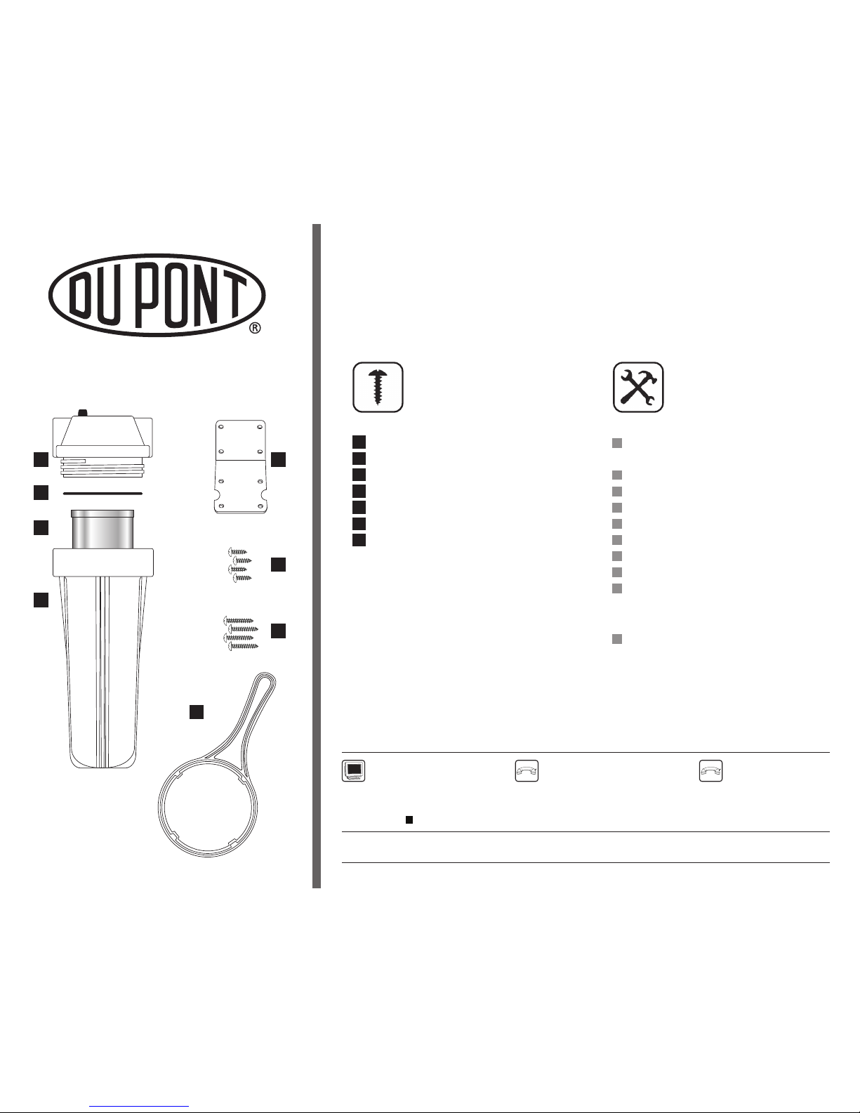
Parts & Hardware Included
Filter System (System Head with Filter Housing)
Filter Cartridge
Filter O-Ring
Filter Housing Wrench
Mounting Bracket
3/4" Mounting Screws (4)
2" Mounting Screws (4)
Tools & Materials Required
Compression Fittings/Valves
(See Step 2: Configure Your System)
Two Adjustable Wrenches
Pipe Wrench
Pipe Cutter or Hacksaw
File
Pencil
Plumber’s Tape
Silicone Grease
Pan or Bucket
Optional Materials
Grounding Kit
Fo r ins tal lation s in Ma ssa ch use tts, the Com mo nwe alth of M ass ach use tts Pl umb ing Cod e C MR248 sh all be adh er ed to.
www.waterfiltration.DuPont.com
Protect Plus, LLC Hickory, NC 28601 USA
866-709-2086 Toll Free
For Service Requests & Product Information
Hours of Operation: 24 Hours/Day, 7 Days/Week
800-441-7515
For Safety & Health Questions
Information & Assistance
System Head
Filter O-Ring
DuPont Part No. WFAO200
Filter Cartridge
Mounting Bracket
DuPont Part No. WFAB200
2" Mounting Screws (4)
Filter Housing
Filter Housing Wrench
DuPont Part No. WFAW200
3/4" Mounting Screws (4)
DuPont Part No. WFAS300 (Package of 2)
A E
F
G
A
C
B
D
A
B
C
D
E
F
G
Page 3
WFPF13003B
2
V4.0
Proper Installation
Please read all instructions, specifications, and precautions before installing and using your water filter system.
Precautions:
After prolonged periods of non-use (such as during a vacation), it is recommended that the system be flushed thoroughly. Let water run
for 10 minutes before using.
The filter cartridges used with this Filter System have a limited
service life. Changes in taste, odor, and/or flow of the water being filtered
indicate that the cartridge should be replaced.
Do not install where system will be exposed to direct sunlight.
Your water filtration system will withstand up to 100 psi water pressure. If your house water supply pressure is higher than 100 psi, install
a pressure reducing valve before the system is installed.
Before You Begin
Locate the main water supply line to your home and check to see what type of plumbing is in place (ex: plastic, copper, galvanized).
The main water supply line is typically located in a basement, crawlspace or garage. For cold water lines only.
Measure the diameter of the existing pipe to determine what size fittings and/or valves (not included) will be required.
Choose a location in the main su
pply line to install the Filter System. Make sure to place the Filter System in an area after the
water meter or pressure tank and before the water heater. Also select a location that will be easily accessible when changing
filter cartridges.
Consult your local plumbing codes and install accordingly.
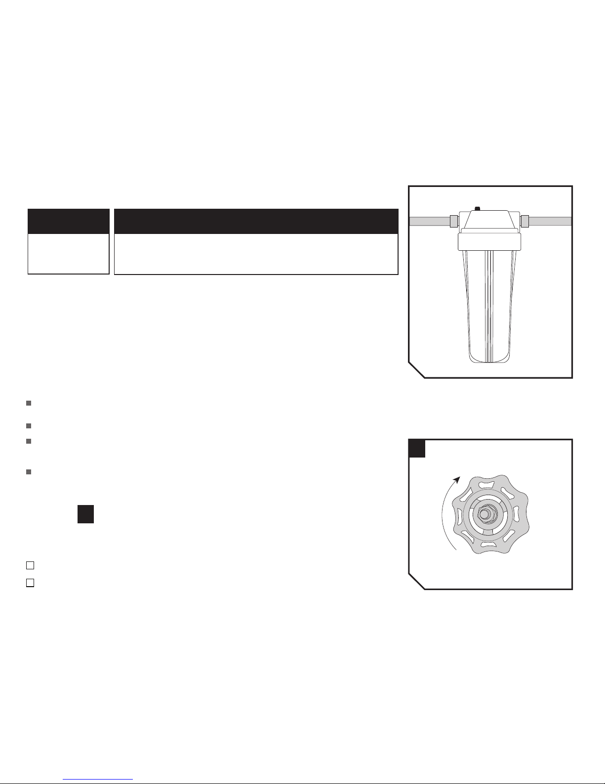
STEP
Turn Off the Main Water Supply Line
NOTE: The Filter System must be installed after the water meter or pressure tank.
Turn off the main water supply line to your home.
Purge all water from the plumbing lines by turning on all faucets in your home and draining completely.
This filter must be protected
from freezing, which can
cause cracking of the filter
and water leakage.
Because of the product’s limited service life and to prevent costly repairs or possible water damage, we strongly
recommend that the housing be replaced every ten years. If the head of the filter has been in use for longer than
this period, it should be replaced immediately. Date the top of any new head to indicate the next recommended
replacement date.
NOTICE NOTICE
1
2
1
1
Page 4
WFPF13003B
3
V4.0
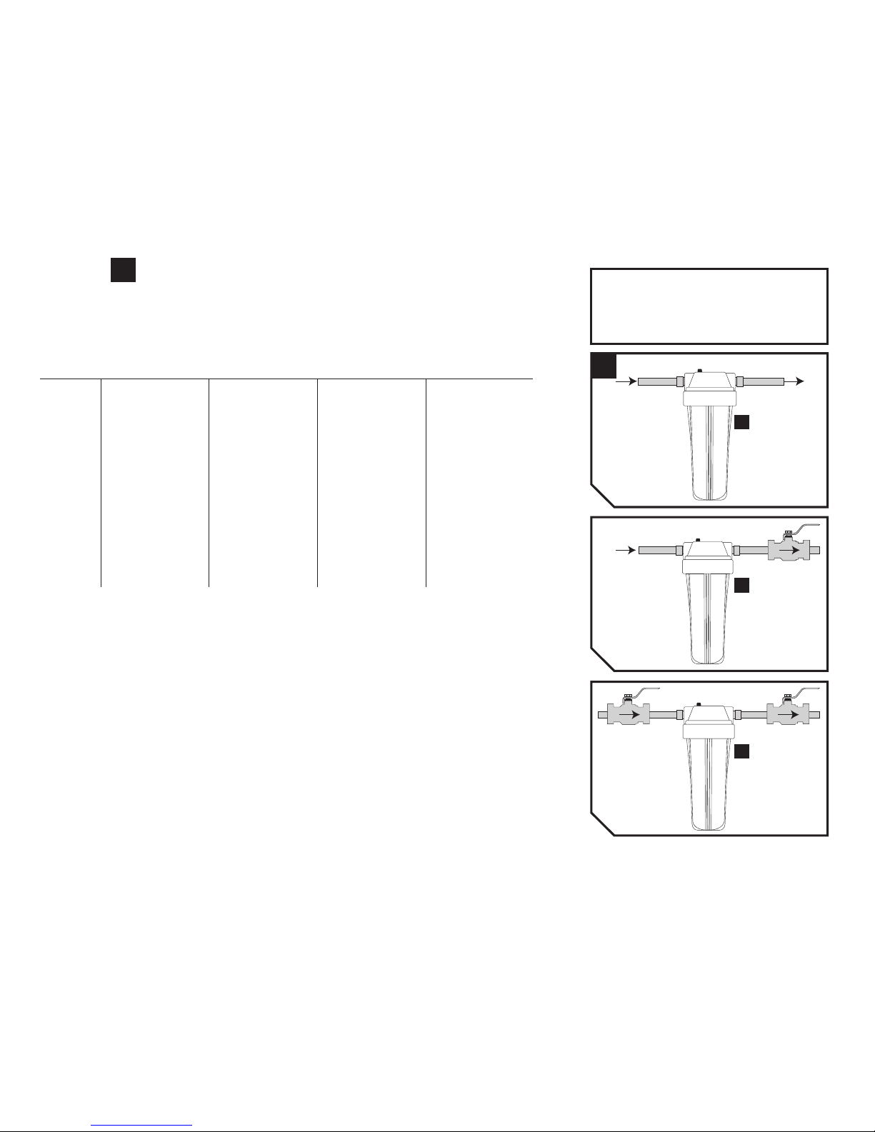
STEP
2
Configure Your System
See the System Configuration Chart to determine how you will configure your Filter System and to identify the additional parts
and tools you will need for installation.
NOTE: For galvanized piping consult a professional plumber.
Materials Needed For 3/4" Diameter Housing Inlet /Outlet Ports
______________________________________________________________________________________________________________________________________
2 3/4" O.D. Tube x 3/4" M.I.P No Individual Fitting. 3/4" NPT x 3/4" Tube 3/4" NPT x 1" Tube
Compression Male Adapter It may be made up of: Male Adapter Male Adapter
or - 1" x 1" sch 40 coupling PVC Slip Type PVC Sli
p Ty
pe
3/4" MPT x 3/4" CTS QC - 1" x 3/4" sch 40 bushing
Adapter (WATTS WaterPEX) - 3/4" sch 80 nipple (2 each)
- 1" CTS QC Adapter
(WATTS WaterPEX)
______________________________________________________________________________________________________________________________________
TOOLS
______________________________________________________________________________________________________________________________________
P
ipe Cutter or Hacksaw Pipe Cutter or Hacksaw Pipe Cutter or Hacksaw Pipe Cutter or Hacksaw
2 Adjustable Wrenches 2 Adjustable Wrenches 2 Adjustable Wrenches 2 Adjustable Wrenches
Tape Measure Tape Measure Tape Measure Tape Measure
______________________________________________________________________________________________________________________________________
SUPPLIES
______________________________________________________________________________________________________________________________________
Plumber’s Tape Plumber’s Tape Plumber’s Tape Plumber’s Tape
PVC Cleaner PVC Cleaner
PVC Adhesive PVC Adhesive
______________________________________________________________________________________________________________________________________
QUANTITY
1" COPPER PIPE
1" PVC PIPE3/4" PVC PIPE
3/4" CO
PPER P
IPE
GOOD
BETTER
BEST
NOTE: Valves shown in diagrams are not included but
can be purchased at a local hardware store.
During filter cartridge replacement it is necessary to shut
off the water supply and purge the water lines. Adding
shut-off valves will isolate the system from the supply
line and household water. In this way, filter cartridge
replacement is faster with less mess and hassle
.
A
A
VALVE
VALVE
VALVE
2
A
Page 5
X
STEP
4
1
2
3
1
2
3
4
WFPF13003B
4
V4.0
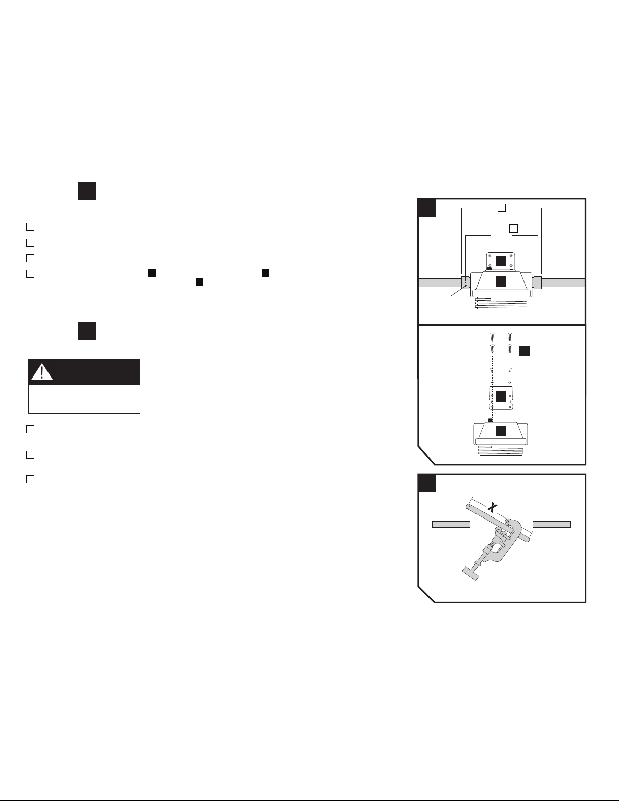
Assemble the System and Install Mounting Bracket
Dry assemble the complete system (according to the configuration chosen), including all fittings and valves.
Measure the overall length (see diagram) of the configured system.
Reduce this measurement enough to allow for the amount of engagement (X) to determine how much pipe to remove from the line.
When installing the Mounting Bracket
E , position it on top of the System Head A , aligning the bracket holes with the holes in
the System Head. Insert the four 3/4" Mounting Screws
F
through the Mounting Bracket and into the holes of the System Head
until tight.
Mark Measurements and Cut the Plumbing Pipe
Mark the section of the plumbing pipe that will need to be removed to allow for the configured system (as determined in Step 3).
NOTE: Measure twice, cut once!
Using a pipe cutter or hacksaw, cut the marked section from the plumbing pipe.
NOTE: Use a pan or bucket to catch any remaining water in the pipes.
Remove any burrs or debris from the cut edges with a file.
Please wear safety glasses to protect
eyes when cutting.
A
SEE CHART
PAGE 3
STEP
3
CAUTION
3
4
2
3
A
E
E
F
A
Page 6
WFPF13003B
5
V4.0
STEP 5
6
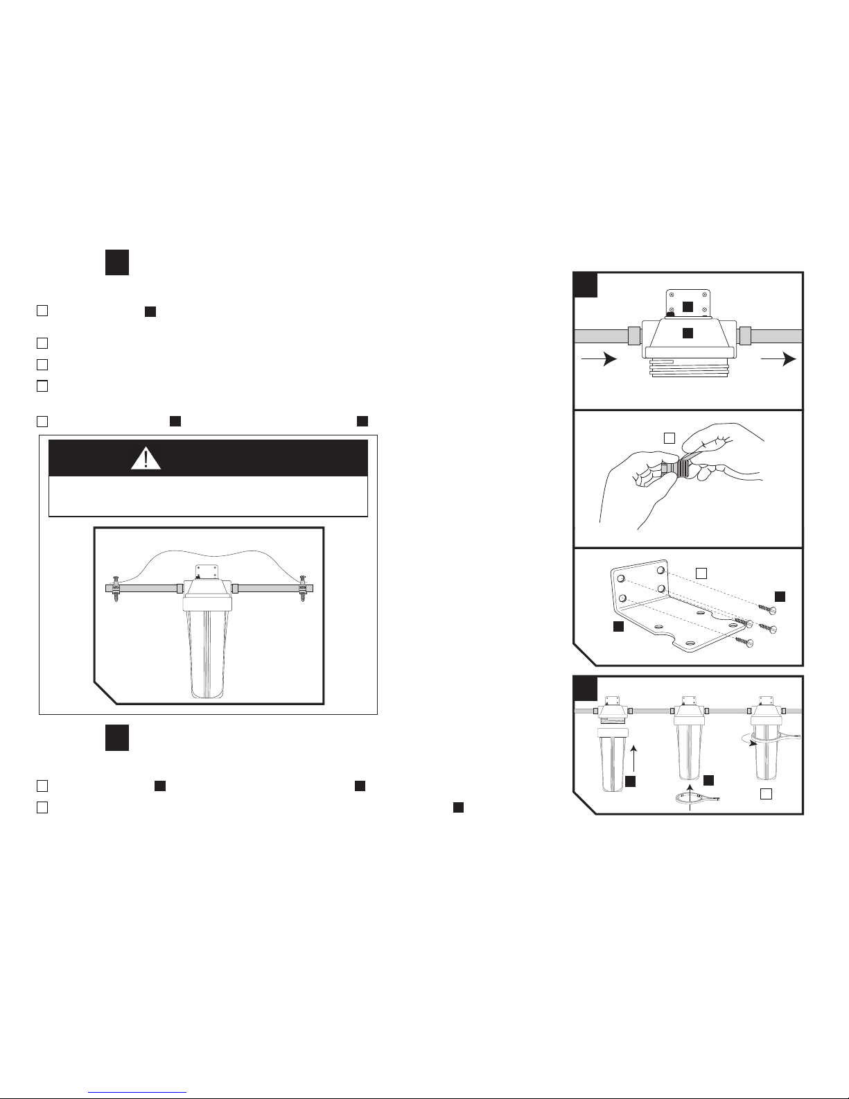
Hang the Filter System Head
1 Align the System Head
A
on the pipes so that the inlet and outlet are in the correct locations. The "in" port on the System Head
should be facing the incoming water supply.
2 Allow the System Head to temporarily hang between the two cut plumbing pipes.
3 Apply plumber’s tape or appropriate sealant to the fittings and lines, according to your system configuration.
4 Make all connections and tighten fittings.
NOTE: Keep the Filter System in an upright position.
5 Attach the Mounting Bracket E to the wall using the four 2" Mounting Screws F or alternative fasteners (not included).
STEP
Hang the Filter Housing
1 Insert the Filter Cartridge B over standpipe in the bottom of the Filter Housing A .
2 Screw the Filter Housing back onto the System Head and hand-tighten. Using the Filter Housing Wrench D , tighten 1/4 turn.
NOTE: Do not over tighten.
A grounding kit (not included) must be installed on water pipes if they are
used to ground electrical systems, appliances or phones.
GROUNDING KIT (NOT INCLUDED)
WATER
FLOW
TO
HOUSE
IN OUT
CAUTION
5
6
A
E
E
G
A
D
3
5
2
Page 7

WFPF13003B
6
V4.0
Test the Filter System for Proper Operation
Slowly turn on the water supply at the main shutoff valve.
Press the red pressure-relief button on top of the Filter System
A to release any trapped air.
Check for any leaks between the System Head and Filter Housing of the Filter System, and on the inlet and outlet connections.
If there are leaks, see the troubleshooting tips below.
Flush the
Filter System for 40 minutes by keeping the nearest faucet turned on.
If there are l eak s betwe en the System H ead and Fi lter Ho using of the Filter System :
Turn off the main water supply to your home.
Purge all water from the plumbing lines by turning on all faucets in your home and drain completely.
Press the red pressure-relief button on top of the Filter System
A to release pressure.
Unscrew and remove the System Head from the Filter System using the Filter Housing Wrench
D .
NOTE: Use a pan or bucket to catch any water in the housing.
Remove the black O-Ring Cand inspect. Clean and lubricate with silicone grease.
Clean the groove in the top of the Filter Housing where the O-Ring sits.
Place the clean, lubricated O-Ring back in the groove.
Screw the Filter Housing back onto the System Head and hand-tighten. Using the Filter Housing Wrench, tighten 1/4 turn.
NOTE: Do not over tighten.
Turn on the main water supply and inspect for leaks.
If there are l eak s on the inle t and/ or outlet co nnections:
Turn off the main water supply to your home.
Purge all water from the plumbing lines by turning on all faucets in your home and drain completely.
Tighten all fittings.
Turn on the main water supply and inspec
t for leaks.
If leaks continue, disassemble the configured system, reapply plumber’s tape or sealant, and reinstall the Filter System.
> If leaks continue, turn off the water supply and call Customer Service.
STEP
7
1
2
3
4
7
2
A
Page 8

WFPF13003B
7
V4.0
Filter Cartridge Replacement
Turn off the main water supply to your home.
NOTE: This will shut off all water flow in the home.
Purge all water from the plumbing lines by turning on all faucets in your home and draining completely.
Press the red pressure-relief button on top of the Filter System
A to release pressure.
Use the Filter Housing Wrench
D
to unscrew the Filter Housing.
NOTE: Use a pan or bucket to catch any water in the Filter Housing.
Pour out the water in the Filter Housing and remove the used Filter Cartridge B .
STEP
NOTE: Have a pan or bucket handy to rinse out the Filter Housing.
Rinse out the bottom of the Filter Housing.
Add enough water to fill the Filter Housing 1/3 full. Add approximately 2 tablespoons of bleach and clean the System Head and
bottom of the Filter Housing with a clean cloth.
Rinse the Filter Housing thoroughly to remove bleach.
Remove the O-Ring
C
in the top of the Filter Housing and wipe clean.
Use silicone grease to lubricate the O-Ring.
Place the O-Ring back in the groove of the Filter Housing.
NOTE: Make sure that the O-Ring is seated properly in the groove to ensure a good seal.
Insert the new Filter Cartridge over the standpipe in the bottom of the Filter Housing.
Screw the Filter Housing back onto the System Head and hand-tighten. Using the Filter Housing Wrench, tighten 1/4 turn.
NOTE: Do not over tighten.
Slowly turn on the water supply at the main shutoff valve.
Press the red pressure-relief button on top of the Filter System to release any trapped air.
Check for any leaks before proceeding. (Refer to troubleshooting on Page 6.)
Turn on
the nearest faucet and flush the Filter System for 40 minutes.
A
STEP
1
STEP
2
STEP
3
1
2
3
4
5
1
2
3
4
5
6
1
2
3
4
5
6
1
3
A
4 4
A
D
A
C
B
A
Page 9

WFPF13003B
8
V4.0
These units are intended for non-commercial use. They should be used only in
ambient air temperature of between 35 degrees F / 2 degrees C and 100 degrees
F / 38 degrees C. Placement of these units in direct sunlight or use of electrical
heating equipment on these units must be avoided. Replace filter cartridge when
and as directed in the installation/ operation instructions included with each
cartridge. Replacement filter cartridges are available at retail outlets.
Operation/Maintenance Data
• These filters are not water purifiers. Do not use with water that is microbiologically
unsafe or of unknown quality without adequate disinfection before or after the
system. Systems certified for Cyst reduction may be used on disinfected waters
that may contain filterable Cysts.
• This unit is not designed to filter sulfur (rotten egg odor). Use of carbon filters to
treat sulfur may intensify taste/odor problems.
• Please comply with all state and local regulations regarding the installation of
water treatment devices.
• The contaminants or other substances reduced by the water filter device are not
necessarily in your water.
CAUTION
Usage and quality of water in your incoming water line affect the life of filter cartridges
and determine when the cartridge should be changed. Cartridges should be replaced
sooner if water pressure at the faucet begins to drop noticeably or if the filter fails to
perform satisfactorily.
Replacement Cartridges
DuPont™ Universal Whole House System
System
Cartridge Model Numbers
________________________________________________________________________________________________
Universal Whole House Model Series WFPF1300 WFPFC3002, WFPFC4002, WFPFC5002,
WFPFC8002, WFPFC9001
________________________________________________________________________________________________
Replacement Parts
DuPont™ Universal Whole House System
Part Number
Description
________________________________________________________________________________________________
WFAB200 Mounting Bracket
________________________________________________________________________________________________
WFAO200 O-Ring
________________________________________________________________________________________________
WFAW200 Filter Housing Wrench
________________________________________________________________________________________________
WFAS300 Mounting Screws (Package of 2)
________________________________________________________________________________________________
www.waterfiltration.DuPont.com
Protect Plus, LLC n Hickory, NC 28601 USA
866-709-2086 Toll Free
For Service Requests & Product Information
Hours of Operation: 24 Hours/Day, 7 Days/Week
Ordering Information:
Page 10

Contenido del embalaje
SISTEMA UNIVERSAL PARA TODA LA CASA
Instrucciones de instalación
Sistema universal de filtrado para toda la casa
Juego universal de filtrado para toda la casa
Piezas y elementos de montaje incluidos
Sistema de filtrado
(cabezal del sistema con carcasa del filtro)
Cartucho del filtro
Retén anular del filtro
Llave para la carcasa del filtro
Soporte de montaje
Tornillos de montaje de 3/4
pulg. (4)
2 tornillos de montaje (4)
Herramientas y materiales necesarios
Válvulas/conexiones de compresión
(Vea el Paso 2: Configuración de su sistema)
2 llaves ajustables
Llave de tubos
Cortador de tubos o sierra cortametales
Lima
Lápiz
Cinta para cañerías
Grasa siliconada
Bandeja o cubo
Materiales opcionales
Conexión de puesta a tierra
Cabezal del
sistema
Retén anular
del filtro
Nº de pieza DuPont WFAO200
Cartucho del filtro
Soporte de montaje
Nº de pieza DuPont WFAB200
2 tornillos de montaje (4)
Carcasa del filtro
Llave para la carcasa
del filtro
Nº de pieza DuPont WFAW200
Tornillos de montaje de 3/4 pulg. (4)
Nº de pieza DuPont WFAS300 (paquete de 2)
Pa ra i nsta lación en Ma ssa chuse tts, se de be cum pli r el Cód igo de Plo mer ía de la M an com un ida d de M ass ach use tts CM R248.
www.waterfiltration.DuPont.com
Protect Plus, LLC Hickory, NC 28601 USA
866-709-2086 Gratis
Para solicitudes de servicio e información de productos
Horarios de atención: Las 24 horas, los 7 días de
la semana
800-441-7515
Para preguntas sobre salud
y seguridad
Información y asistencia
A E
F
G
A
C
B
D
A
B
C
D
E
F
G
Page 11

WFPF13003B
10
V4.0
Instalación correcta
Antes de instalar y usar su sistema de filtrado de agua, lea todas las instrucciones, especificaciones y precauciones.
Precauciones:
Después de períodos prolongados sin uso (como durante las vacaciones), es recomendable lavar a fondo el sistema. Deje correr el agua
durante 10 minutos antes de usarlo.
Los cartuchos de filtro usados con este sistema de filtrado tiene
n una vida útil limitada. Los cambios en el sabor, olor y/o caudal del agua
filtrada indican que debe reemplazarse el cartucho.
No instale el sistema en lugares donde esté expuesto a la luz solar directa.
Su sistema de filtrado de agua soporta hasta 100 psi de presión de agua. Si la presión del suministro de agua entrante a su casa es
superior a 100 psi, instale una válvula reductora de presión antes
de instalar el sistema.
Antes de comenzar
Localice la tubería de suministro de agua entrante a su casa y verifique qué tipo de cañerías están colocadas (por ej.: plástica,
metálica o de cobre). La tubería de suministro de agua se encuentra habitualmente en el sótano, en el espacio vacío debajo del
piso o en el garaje. Para la agua fría alinea solamente.
Mida el diámetro del caño existente para determinar el tamaño de las conexiones y/o válvulas (no incluidas) que se necesitarán.
Elija un lugar en la tubería de suministro donde instalar el sistema de filtrado. Asegúrese de colocar el sistema de filtrado en un
área después del medidor de agua o tanque de presión y antes del calentador de agua. Seleccione también un lugar de fácil
acceso para cambiar los cartuchos del filtro.
Consulte los códigos
de plomería locales y realice la instalación de acuerdo a los mismos.
PASO
Corte del suministro de agua
NOTA: El sistema de filtrado debe instalarse después del medidor de agua o tanque de presión.
Corte el suministro de agua entrante a su casa.
Purgue toda el agua existente en las cañerías abriendo todos los grifos de su casa y desagotándolos completamente.
Este filtro debe estar protegido
contra el congelamiento, que
puede causar rajaduras y
érdidas de agua.
Puesto que el producto tiene una vida útil limitada y a fin de evitar reparaciones costosas o posibles daños
al agua, recomendamos especialmente reemplazar la carcasa cada diez años. Si el cabezal del filtro ha
estado en uso un tiempo mayor que este período, debe reemplazarse inmediatamente. Ponga la fecha en la
parte superior del cabezal nuevo para indicar la próxima fecha de reemplazo recomendada.
AVISO AVISO
1
1
2
1
Page 12

A
A
A
WFPF13003B
11
V4.0
Configuración de su sistema
Vea la tabla de configuración del sistema para determinar cómo configurará su sistema de filtrado y para identificar las piezas y herramientas adicionales que necesitará para la instalación.
NOTA: En relación con las cañerías galvanizadas, consulte a un plomero profesional.
BUENO
MEJOR
LO MEJOR
NOTA: Las válvulas mostradas en los diagramas
no están incluidas pero se pueden comprar
en una tienda de sanitarios local.
Materiales necesarios para orificios de entrada y salida de la carcasa de 3/4"
______________________________________________________________________________________________________________________________________
2 Adaptador macho de compresión Sin accesorios de conexión Tu
bo de 3/4" NPT x 1" Tubo de 3/4" NPT x 1"
de tubo de 3/4" D.E. x 3/4" M.I.P individuales Adaptador macho Adaptador macho
o Puede estar compuesto por: PVC tipo deslizante PVC tipo deslizante
Adaptador QC de 3/4" MPT x - Acoplador de 1" x 1" sch 40
3/4" CTS (WATTS WaterPEX) - Buje de 1" x 3/4" sch 40
- Niple de 3/4" sch 80 (2 unidades)
- Adaptador QC de 1" MPT x
1" CTS (WATTS WaterPEX)
___________________
___________________________________________________________________________________________________________________
H
ERRAMIENTAS
______________________________________________________________________________________________________________________________________
Cortador de tubos o sierra Cortador de tubos o sierra Cortador de tubos o sierra Cortador de tubos o sierra
cortametales cortametales cortametales cortametales
2 llaves ajustables 2 llaves ajustables 2 llaves ajustables 2 llaves ajustables
Cinta métrica Cinta métrica Cinta métrica Cinta métrica
______________________________________________________________________________________________________________________________________
INSUMOS
______________________________________________________________________________________________________________________
________________
C
inta para cañerías Cinta para cañerías Cinta para cañerías Cinta para cañerías
Limpiador de PVC Limpiador de PVC
Adhesivo para PVC Adhesivo para PVC
______________________________________________________________________________________________________________________________________
CANTIDAD
CAÑO DE COBRE DE 1"
CAÑO DE PVC DE 1"CAÑO DE PVC DE 3/4"
CAÑO DE COBRE DE 3/4"
VÁLVULA
VÁLVULA
VÁLVULA
Durante el reemplazo del cartucho del filtro, es necesario
cortar el suministro de agua y purgar las tuberías. Si se
agregan válvulas de paso, el sistema se aísla de la tubería
de suministro y el agua domiciliaria. De esta manera, el
reemplazo del cartucho del filtro es más rápido con menos
trabajo y molestias.
PASO
2
2
Page 13

X
2
3
A
E
E
F
WFPF13003B
12
V4.0
Armado del sistema e instalación del soporte de montaje
Arme en seco el sistema completo (de acuerdo a la configuración elegida), incluidos todos los accesorios de conexión y válvulas.
Mida la longitud exterior total (vea el diagrama) del sistema configurado.
Reduzca esta medida lo suficiente para tener en cuenta la longitud de acoplamiento (X) a fin de determinar cuánto caño hay que
sacar de la tubería.
Cuando instale el soporte de montaje
E , posiciónelo en la parte superior del cabezal del sistema A , alineando los orificios del
soporte de montaje con los orificios del cabezal. Inserte los cuatro tornillos de montaje de 3/4"
F
a través del soporte de montaje
en los orificios del cabezal del sistema hasta que queden apretados.
Marcado de las medidas y corte de la cañería
Marque la sección de la cañería de suministro que debe remover a fin de permitir la instalación del sistema configurado
(determinada en el Paso 3).
NOTA: ¡Mida dos veces, corte una vez sola!
Corte con un cortador de tubos o sierra para metales la sección marcada en la cañería.
NOTA: Use una bandeja o un cubo para recoger el agua que caiga de los caños.
Elimine las rebabas o residuos de los bordes cortados con una lima.
Use gafas de seguridad para protegerse los ojos
mientras corta.
CONSULTE LA
TABLA DE LA
PÁGINA 22.
PASO
3
PASO
4
1
2
3
1
2
3
4
3
4
A
PRECAUCIÓN
Page 14

WFPF13003B
13
V4.0
PASO
Colgado del cabezal del sistema de filtrado
Alinee el cabezal del sistema con los caños, de modo que la entrada y la salida estén en las posiciones correctas. El orificio
marcado "in" del cabezal del sistema debe mirar al suministro entrante de agua.
Deje el cabezal del sistema colgando temporalmente entre los dos caños de suministro cortados.
Aplique cinta para cañerías o un sellador apropiado a los accesorios de conexión y las tuberías, de acuerdo a la configuración
de su sistema.
Haga todas las conexiones y apriete los accesorios de conexión.
NOTA: Mantenga el sistema de filtrado en posición vertical.
Fije el soporte de montaje a la pared mediante los cuatro tornillos de montaje de 2" o elementos alternativos (no incluidos).
PASO
Colgado de la carcasa del filtro
Inserte el cartucho del filtro sobre el tubo vertical de la parte inferior de la carcasa del filtro .
Enrosque nuevamente la carcasa del filtro en el cabezal del sistema y apriétela con la mano. Usando la llave para la carcasa ,
apriétela 1/4 de vuelta.
NOTA: No la sobreapriete.
Debe instalarse en las cañerías de agua una conexión de puesta a tierra
(no incluida) si las mismas se usan para poner a tierra sistemas eléctricos,
electrodomésticos o teléfonos.
CONEXIÓN DE PUESTA A TIERRA (NO INCLUIDA)
CIRCULACIÓN
DEL AGUA
A LA CASA
ENTRADA SALIDA
A
E
PRECAUCIÓN
5
6
5
6
1
2
3
4
5
1
2
A
E F
B A
D
A
E
E
G
A
D
3
5
2
Page 15

WFPF13003B
14
V4.0
Prueba del funcionamiento correcto del sistema de filtrado
Abra lentamente la válvula de suministro de agua en la llave de paso.
Pulse el botón rojo de alivio de presión de la parte superior del sistema de filtrado
A
para descargar el aire que podría
haber atrapado.
Verifique que no haya pérdidas entre el cabezal del sistema y la carcasa del filtro del sistema de filtrado, así como en las
conexiones de entrada y salida. Si hay pérdidas, consulte los consejos para la solución de problemas más abajo.
Lave el sistema de filtrado durante 40 minutos manteniendo abierto el grifo más cercano.
Si ha y pérdidas entre e l cabeza l del sistem a y la c arcasa del filtro d el sis tema de filtrado:
Corte el suministro de agua entrante a su casa.
Purgue toda el agua existente en las cañerías abriendo to
dos los grifos de su casa y desagotándolos completamente.
Pulse el botón rojo de alivio de presión de la parte superior del sistema de filtrado
A
para descargar la presión.
Desenrosque y retire del sistema de filtrado el cabezal del sistema usando la llave para la carcasa
D
.
NOTA: Use una bandeja o un cubo para recoger el agua que caiga de la carcasa.
Retire el retén anular negro del filtro Ce inspecciónelo. Límpielo y lubríquelo con grasa siliconada.
Limpie las acanaladuras de la parte superior de la carcasa del filtro donde se asienta el retén anular.
Coloque nuevamente el retén anular limpio y lubricado en la acanaladura.
Enrosque nuevamente la carcasa del filtro en el cabezal del sistema y apriétela con la mano. Usando la llave para la
carcasa, apriétela 1/4 de vuelta.
NOTA: No la sobreapriete.
Abra el suministro de agua y fíjese si hay pérdidas.
Si ha y pérdidas en la s conexione s de e ntrada y/o sali da:
Corte el suministro de agua entrante a su casa.
Purgue toda el agua existente en las cañerías abriendo todos los grifos de su casa y desagotándolos completamente.
Apriete todos los accesorios de conexión.
Abra el suministro de agua y fíjese si hay pérdidas.
Si las pérdidas persisten, desarme el
sistema configurado, vuelva a aplicar cinta o sellador para cañerías y reinstale el
sistema de filtrado.
Si las pérdidas persisten, corte el suministro de agua y llame al Servicio al Cliente.
7
2
A
PASO
7
>
1
2
3
4
Page 16

WFPF13003B
15
V4.0
Reemplazo del cartucho del filtro
Corte el suministro de agua entrante a su casa.
NOTA: De esta forma se corta todo el suministro de agua a la casa.
Purgue toda el agua existente en las cañerías abriendo todos los grifos de su casa y desagotándolos completamente.
Pulse el botón rojo de alivio de presión de la parte superior del sistema de filtrado
A
para descargar la presión.
Use la llave para la carcasa del filtro
D
a fin de desenroscar la carcasa del filtro.
NOTA: Use una bandeja o un cubo para recoger el agua que caiga de la carcasa
Vierta el agua existente en la carcasa del filtro y retire el cartucho del filtro usado B.
NOTA: Tenga una bandeja o un cubo a mano para enjuagar el agua de la carcasa del filtro.
Enjuague la parte inferior de la carcasa del filtro.
Agregue suficiente agua como para llenar 1/3 de la carcasa. Agregue aproximadamente 2 cucharas soperas de blanqueador y
limpie el cabezal del sistema y la parte inferior de la carcasa del filtro con un paño limpio.
Enjuague a fondo la carcasa del filtro con agua limpia para eliminar el blanqueador.
Retire el retén anular
C
de la parte superior de la carcasa del filtro y límpielo.
Use grasa siliconada para lubricar el retén anular.
Coloque nuevamente el retén anular en la acanaladura de la carcasa del filtro.
NOTA: Asegúrese de que el retén anular se asiente correctamente en la acanaladura a fin de asegurar un buen sellado.
Inserte el nuevo cartucho del filtro sobre el tubo vertical de la parte inferior de la carcasa del filtro.
Enrosque nuevamente la carcasa del filtro en el cabezal del sistema y apriétela con la mano. Usando la llave para la carcasa,
apriétela 1/4 de vuelta.
NOTA: No la sobreapriete.
Abra lentamente la válvula de suministro de agua en la llave de paso.
Pulse el botón rojo de alivio de presión de la parte superior del sistema de filtrado para descargar el aire que podría haber atrapado.
Fíjese si hay alguna pérdida antes de continuar. (Consulte la solución de problemas en la página 23).
Abra el grifo más cercano y lave el sistema de filtrado durante 40 minutos.
A
1
3
A
4 4
A
D
A
C
B
A
PASO
1
PASO
2
PASO
3
1
2
3
4
5
1
2
3
4
5
6
1
2
3
4
5
6
Page 17

WFPF13003B
16
V4.0
El consumo y la calidad del agua de su línea de suministro entrante afectan a la vida útil
de los cartuchos de filtro y determinan cuándo deben reemplazarse. Los cartuchos deben
reemplazarse anticipadamente si la presión de agua en el grifo comienza a decaer
perceptiblemente o si el filtro no funciona satisfactoriamente.
Cartuchos de repuesto
Dupont™ sistema universal de filtrado para toda la casa
Sistema
Números de modelo del cartucho
________________________________________________________________________________________________
Sistema universal de filtrado WFPFC3002, WFPFC4002, WFPFC5002,
Model Series WFPF1300 WFPFC8002 y WFPFC9001
________________________________________________________________________________________________
Piezas de repuesto
Dupont™ sistema universal de filtrado para toda la casa
Número de pieza
Descripción
________________________________________________________________________________________________
WFAB200 Soporte de montaje
________________________________________________________________________________________________
WFAO200 Retén anular
________________________________________________________________________________________________
WFAW200 Llave para la carcasa del filtro
________________________________________________________________________________________________
WFAS300 Tornillos de montaje (paquete de 2)
________________________________________________________________________________________________
www.waterfiltration.DuPont.com
Protect Plus, LLC n Hickory, NC 28601 USA
866-709-2086 Gratis
Para solicitudes de servicio e información de productos
Horarios de atención: Las 24 horas, los 7 días de la semana
Información para pedidos:
Estas unidades están diseñadas para uso no comercial. Deben usarse únicamente
con temperaturas de aire ambiental entre 35 grados F (2 grados C) y 100 grados
F (38 grados C). Debe evitarse colocar estas unidades bajo la luz solar directa o
usar equipos calefactores eléctricos en las mismas. Reemplace el cartucho del filtro
cuando y como se explica en las instrucciones de instalación y operación incluidas
con el cartucho. Los cartuchos de filtro de repuesto están disponibles en las tiendas
minoristas.
Datos de operación y mantenimiento
• Estos filtros no son purificadores de agua. No los use con agua microbiológica
mente insegura o de calidad desconocida sin una desinfección adecuada antes o
después del sistema. Pueden usarse sistemas certificados para reducción de
cistes para aguas desinfectadas que puedan contener cistes filtrables.
• Esta unidad no está diseñada para filtrar azufre (olor a huevos podridos). El uso
de filtros de carbón para tratar el azufre puede intensificar los problemas de sabor
y olor.
• Cumpla todas las regulaciones estatales y locales relativas a la instalación de
dispositivos de tratamiento de agua.
• Los contaminantes u otras sustancias reducidas por este filtro no están necesaria
mente presentes en el agua que usted usa.
PRECAUCIÓN
Page 18

WFPF13003B
17
V4.0
Page 19

WFPF13003B V4.0
Elecciones más inteligentes para un mundo más limpio
La creación de mejores productos para usted y su familia es lo que puede esperarse de DuPont.
El producto que contiene este paquete se creó cumpliendo exigentes normas de calidad y eficacia.
Mejora del sabor y calidad probadas y certificadas en forma independiente
©2009 Protect Plus, LLC. La marca H2O es una marca de Protect Plus. El logotipo DuPont Oval Logo®, DuPont™,
The miracles of science™ son marcas de fábrica o marcas registradas de E. I. du Pont de Nemours and Company o sus afiliadas.
Todos los derechos reservados.
Page 20

WFPF13003B V4.0
Smarter Choices for a Cleaner World
Creating better products for you and your family is what you can expect from DuPont.
The product inside this package was created adhering to high standards in quality and efficacy.
Independently Tested and Certified to Improve Taste and Water Quality
© 2009 Protect Plus, LLC. H2O Trademark is a trademark of Protect Plus.
The DuPont Oval Logo®, DuPont™, The miracles of science™ are trademarks or registered trademarks of E. I. du
Pont de Nemours and Company or it affiliates. All rights reserved.
 Loading...