

Page 1
,943
TMA
Thermomechanical Analyzer
-------------------------
Operator's Manual
~
REG. U.S. PATs.TM. OfF.
Page 2
Thermal Analyzers
Instrument Systems
Operator's Manual
943
Thermomechanical
Analyzer
Du Pont Company
Instrument Systems
Concord Plaza - Quillen Building
Wilmington, OE 19898
PN 943145-000, Rev. F
Issued April 1985
Page 3

INTRODOCTION
Page 4
HEATER
4/79B
943/1
Introduction
Introducing the 943 TMA
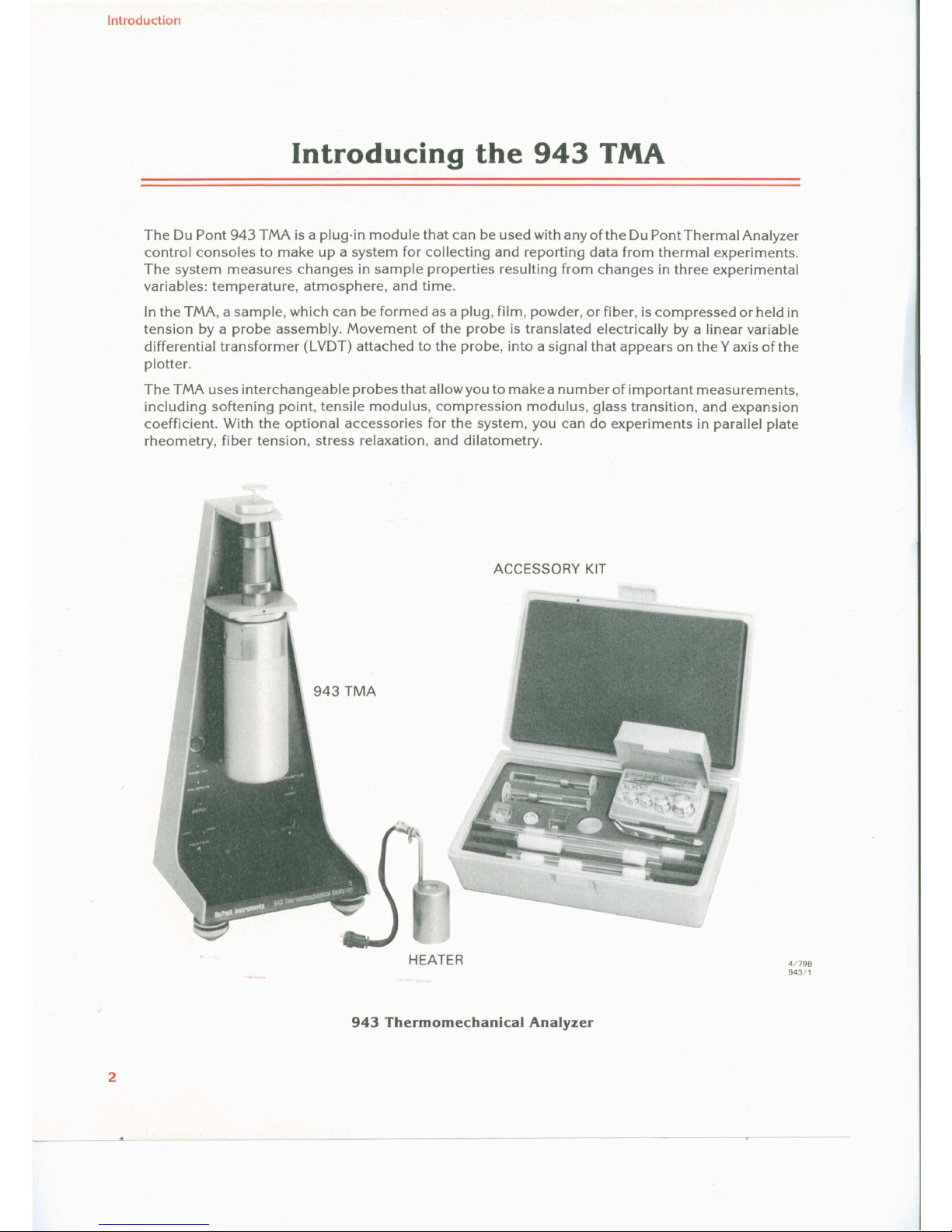
The Du Pont 943 TMA isa pluq-in module that can be used with any of the Du Pont Thermal Analyzer
contra I consoles to make up a system for collecting and reporting data from thermal experiments.
The system measures changes in sampie properties resulting from changes in three experimental
variables: temperature, atmosphere, and time.
In the TMA, a sampie, which can be formed as a plug, film, powder, or fiber, iscompressed or held in
tension by a probe assembly. Movement of the probe is translated electrically by a linear variable
differential transformer (LYDT) attached to the probe, into asignal that appears on the Y axis of the
plotter.
The TMA uses interchangeable probes that allow you to make anumber of important measurements,
including softening point, tensile modulus, compression modulus, glass transition, and expansion
coefficient. With the optional accessories for the system, you can do experiments in parallel plate
rheornetry, fiber tension, stress relaxation, and dilatometry.
ACCESSORY KIT
943 Thermomechanical Analyzer
2
Page 5
3
Introduction
SYSTEM COMPONENTS
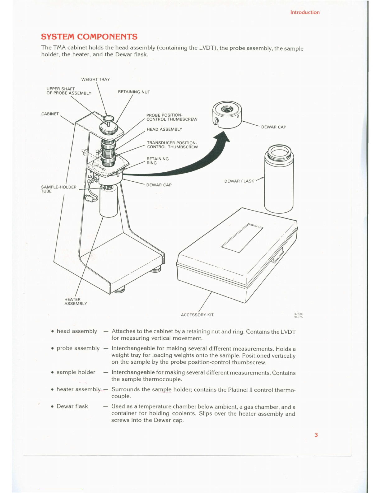
The TMA cabinet holds the head assembly (containing the LVDT), the probe assembly, the sampIe
holder, the heater, and the Dewar flask.
WEIGHT TRAY
UPPER SHAFT
OF PROBE ASSEMBLY
PROBE POSITION-
CONTROL THUMBSCREW
HEAD ASSEMBLY
DEWAR CAP
TRANSDUCER POSITION-
CONTROL THUMBSCREW
DEWAR FLASK ./""
HEATER
ASSEMBLY
ACCESSORY KIT
4/83C
943/5
• head assembly Attaches to the cabinet by a retaining nut and ring. Contains the LVDT
for measuring vertical movement.
• probe assembly - lnterchangeable for making several different measurements. Holds a
weight tray for loading weights onto the sampIe. Positioned vertically
on the sampIe by the probe position-control thumbscrew.
• sampIe holder lnterchangeable for making several different measurements. Contains
the sam pIe thermocouple.
• heater assembly :-:- Surrounds the sarnple holder; contains the Platinel 11control thermo-
coupIe.
• Dewar flask
Used as a temperature chamber below ambient, agas chamber, and a
container for holding coolants. Slips over the heater assembly and
screws into the Dewar cap.
Page 6
Introduction
ACCESSORY KIT
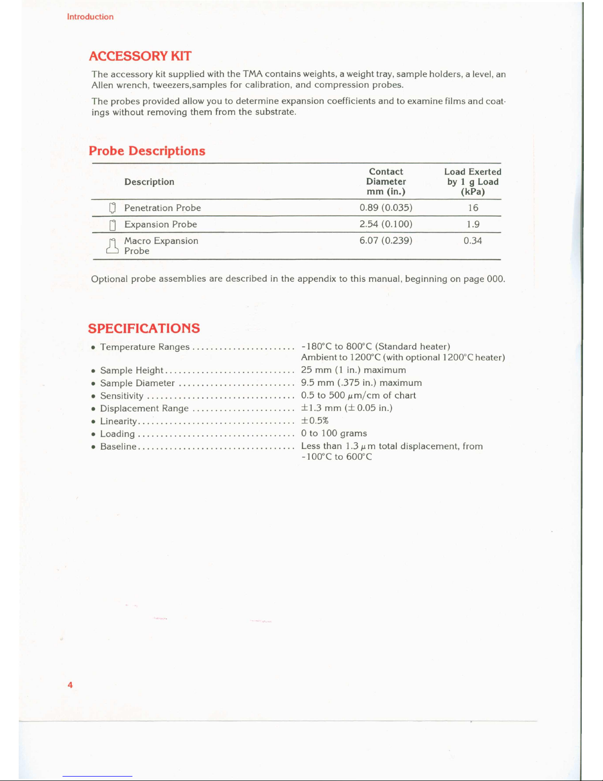
The accessory kit supplied with the TMA contains weights, a weight tray, sam pie holders, a level, an
Allen wrench, tweezers,samples for calibration, and compression probes.
The probes provided allow you to determine expansion coefficients and to examine films and coat-
ings without removing them from the substrate.
Probe Descriptions
Contact
Load Exerted
Description
Diameter
by
1 9 Load
mm
(ln.)
(kPa)
0
Penetration Probe
0.89 (0.035)
16
D
Expansion Probe
2.54 (0.100)
1.9
l1
Macro Expansion
6.07 (0.239)
0.34
Probe
Optional probe assemblies are described in the appendix to this manual, beginning on page
000.
SPECIFICATIONS
• Temperature Ranges
-180
o
e to
800
0
e (Standard heater)
Ambient to
1200
0
e (with
optionallZüü'C heater)
• Sampie Height. . . . . . . . . . . . . . . . . . . . . . . . . . . ..
25
mm(1in.) maximum
• Sampie Diameter. . . . . . . . . . . . . . . . . . . . . . . . ..
9.5
mm
(.375
in.) maximum
• Sensitivity
0.5to500
Mm/cm of chart
• Displacement Range
±1.3
mm
(± 0.05
in.)
• Linearity ... :...............................
± 0.5%
• Loading . . . . . . . . . . . . . . . . . . . . . . . . . . . . . . . . . ..0to
100
grams
• Baseline................................... Less than
1.3
Mm total displacement, from
-100
o
e to
600
0
e
4
Page 7

INSTALLATION
Page 8
CAUTION -----------------,
Installation
Installing the 943 System
When you receive the 943 TMA, inspect the instrument and shipping container for signs of shipping
damage, and check the parts received against the shipping list. If the instrument isdamaged, notify
the carrier and Du Pont Instruments immediately. If the instrument is intact but parts are missing,
notify Du Pont Instruments. You will find a list of Du Pont offices on the back cover of this manual.
ASSEMBLING THE TMA
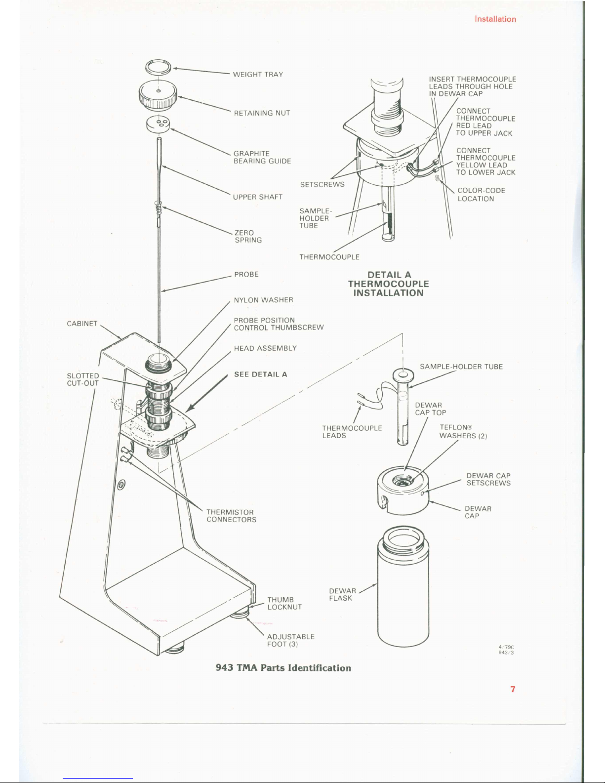
1. Holding the Dewar cap in one hand, unscrew the Dewarf1askfrom the cap. Referto the figure on
.page 7 for parts identification.
2. Remove the Dewar cap from the TMA head assembly.
The sarnple-holder tube is fragile and should be handled with care.
3. Select a sarnple-holder tube from the accessory kit and insert it through the top of the Dewar
cap. Two teflon washers are used between the holder and cap.
4. Replace the Dewar cap on the head assembly; hand tighten. The hole in the Dewar cap should
face the thermocouple connectors on the front of the TMA cabinet. If necessary, loosen the
setscrews in the Dewar cap with the Allen wrench supplied in the accessory kit. Turn the Dewar
cap until the' hole faces the thermocouple connectors and tighten the setscrews.
5. Using the tweezers from the accessory kit, thread the thermocouple leads through the hole in
the Dewar cap (see detail A on page7).
...----------------- NOTE ----------------,
Make sure that the bare thermocouple wires do not touch, asthis could cause erroneous
readings.
6. Connect the red thermocouple lead to the upper connector and the yellow lead to the lower
connector.
7. Remove the retaining nut from the top of the TMA head assembly. Do not remove the nylon
washer beneath the nut.
8. Use tweezers to remove the bearing guide. Two holes are provided in the guide for easy
removal.
9. Make sure that the probe position-control thumbscrew is above the half-way point on the
slotted cutout in the head assembly. Turn the thumbscrew counterclockwise to move it up.
~--------------- CAUTION ----------------,
• Do not drop the probe assembly into position; the delicate sarnple-holder tube could be
broken. .....-
• Try not to move the probe assembly from sideto side while installing it. Side movement
may bend or break the probe.
6
Page 9
o
WEIGHTTRAY
~...__________ RETAINING NUT
~
~ GRAPHITE
~ BEARING GUIDE
~ UPPER SHAFT
~ZERO
SPRING
Installation
~~~~;J~~~tJ1gS~~~~E
IN DEWAR CAP
~
CONNECT
THERMOCOUPLE
t
RED LEAD
TO UPPER JACK
.-<
CONNECT
THERMOCOUPLE
YELLOW LEAD
TO LOWER JACK
COLOR-CODE
LOCATION
SAMPLE-
HOLDER
TUBE
THERMOCOUPLE
DETAIL A
THERMOCOUPLE
INSTALLATION
PROBE
------- NYLON WASHER
PROBE POTSHIT0~NBSCREW
CONTROL
HEAD ASSEMBLY
THUMB
LOCKNUT
ADJUSTABLE
FOOT (3)
SAMPLE-HOLDER TUBE
DEWAR
CAP TOP
TEFLON®
WASHERS (2)
DEWAR CAP
SETSCREWS
DEWAR
CAP
DEWAR/
FLASK
4179C
943/3
943 TMA Parts Identification
7
Page 10
Installation
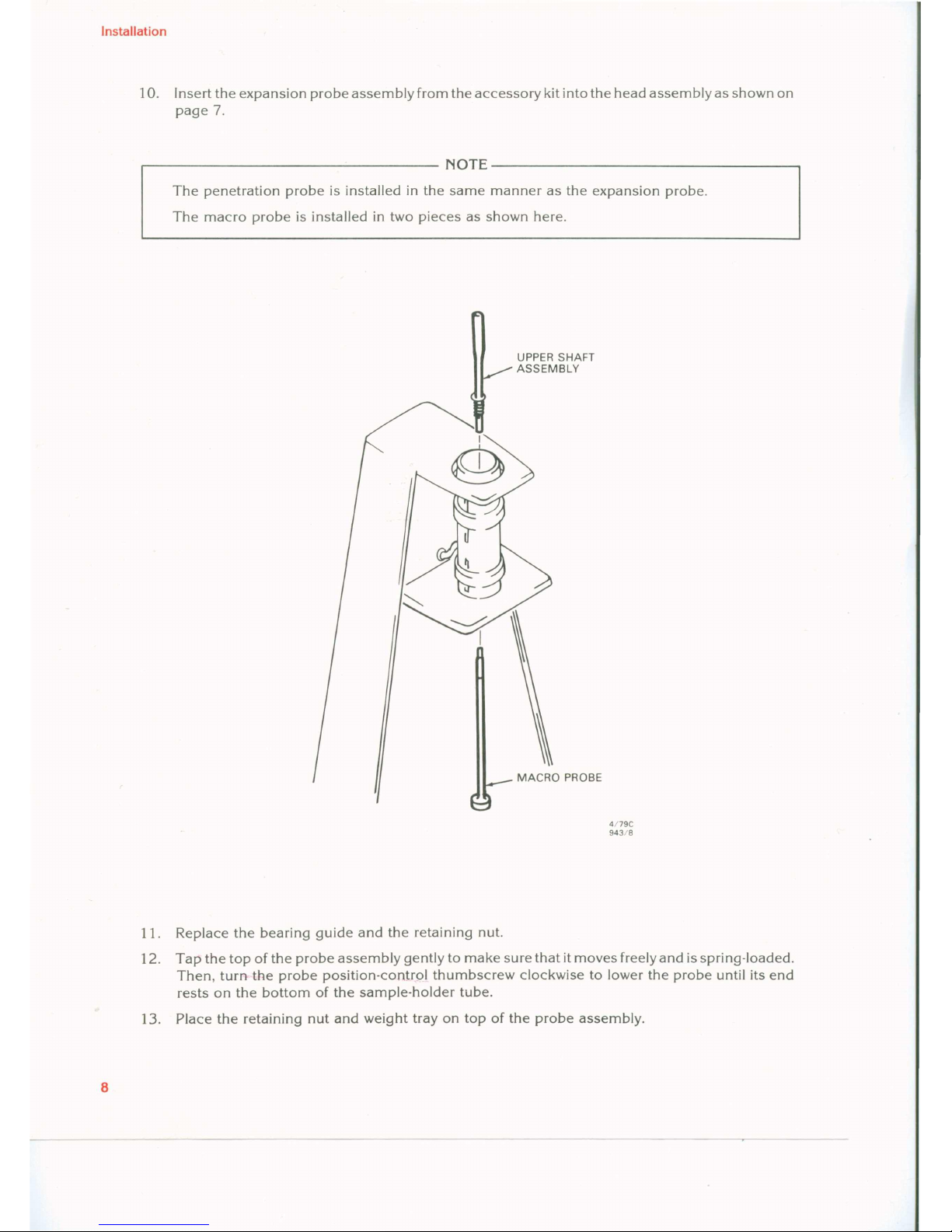
The penetration probe is installed in the same manner as the expansion probe.
The macro probe is installed in two pieces as shown here.
10. Insert the expansion probe assembly from the accessory kit into the head assembly as shown on
page 7.
r------------------------------NOTE-------------------------------.
UPPER SHAFT
ASSEMBLY
MACRO PROBE
4179C
943/8
11. Replace the bearing guide and the retaining nut.
12. Tap the top of the probe assembly gently to make sure that itmoves freely and is spring-loaded.
Then, turn the probe position-control thumbscrew clockwise to lower the probe until its end
rests on the bottom of the sam pie-holder tube.
13. Place the retaining nut and weight tray on top of the probe assembly.
8
Page 11
9
Installation
14. Place the TMA next to the programmer. The instrument should be on a vibration-free bench or
marble benchtop. Observe the following precautions:
• Do not locate the TMA near air conditioning or heating vents.
• Avoid locations where there are high levels of corrosive gases (such as sulfur dioxide or
hydrogen chloride), or where ventilation is poor.
• Avoid dusty locations and places where vibrations occur.
15. Place the level from the accessory kit on top of the weight tray. Level the TMA by adjusting the
three leveling feet on the base of the cabinet. To adjust the feet, loosen the thumb locknut for
all three feet and screw the feet into or out of the cabinet. When the instrument is level, tighten
the thumb locknuts and remove the level from the weight tray.
16. Raise the probe approximately 2 cm (1 in.) from the bottom of the sarnple-holder tube by turn-
ing the probe position-control thumbscrew counterclockwise.
17. Remove the weight tray, retaining nut, and bearing guide from the TMA.
18. Check probe alignment by looking down into the head assembly and observing the gap be-
tween the lower bearing and the probe. Ifthe probe appears to be touching the side of the head
assembly, rotate it until the gap is uniform around the probe.
19. Reinstall the bearing guide, retaining nut, and weight tray. Lower the probe until it rests on the
bottom of the sam pie-holder tube .
.------------------ CA(JTION -----------------,
Do not load the weight tray unless the probe is touching either the sample-holder tube
bottom or a sampIe.
20. Check the thermocouple connections for tightness.
HOOK-OP
To connect the 943 TMA to the programmer:
1. Make sure that the programmer power is off, and that the programmer power cord is unplugged
from the wall outlet. The 943 connector (marked ACCESSORY) is located on the back of the
unit. The cable and connector are keyed so that they can only be connected one way.
2. Connect the accessory cable from the programmer to the TMA.
3. Connect the programmer power cord to the wall outlet.
4. If you wish to use inert or reactive gases for testing, attach the external gas supply tube to
the TMA gas purge connection on the back of the instrument. The TMA is now ready for cali-
bration. Calibration procedures appear in part 3 of the manual.
Page 12

OPERATION
Page 13
Operation
Performing Routine Experiments
This section contains routine operating procedures for the 943 TMA. The section is divided into the
following parts:
• 943 Controls
• Heater Installation
• Dewar Flask Installation
• Applications Notes
• Calibration Procedures
• Routine Operating Sequence
• Subambient Operation
Specific instructions for operating the TMA with each of the optional accessories appear in the
appendix of the rnanual, beginning on page 000.
Before operating the TMA, you should have the unit instalIed and connected to a TA programmer.
943 CONTROLS
Controls for the 943 TMA are located on the front and rear panels of the cabinet. They are described
in the tables that follow.
12
Page 14
Operation
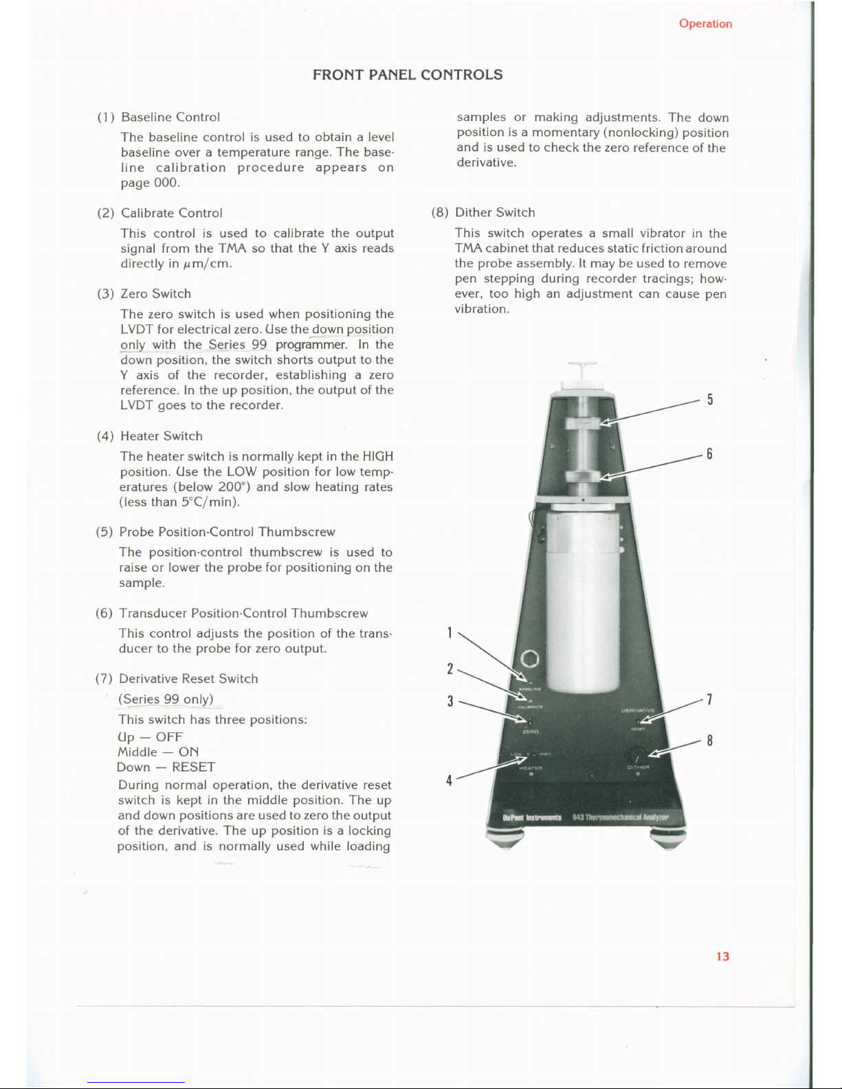
FRONT PANEL CONTROLS
(1) Baseline Control
The baseline control is used to obtain a level
baseline over a temperature range. The
base-
line calibration procedure appears on
page 000.
(2) Calibrate Control
This control is used to calibrate the output
signal from the TMA so that theYaxis reads
directly in
J.Lmjcm.
(3)
Zero Switch
The zero switch is used when positioning the
LVDT for electrical zero. Usethe down position
only with the Series
99
pragrcilTI"mer.In the
down position, the switch shorts output to the
Y
axis of the recorder, establishing a zero
reference. In the up position, the output of the
LVDT goes to the recorder.
(4)
Heater Switch
The heater switch is normally kept in the HIGH
position. Use the LOW position for low
ternp-
eratures (below 200°) and slow heating rates
(Iess than 5°Cjmin).
(5) Probe
Position-Control
Thumbscrew
The position-control thumbscrew is used to
raise or lower the probe for positioning on the
sampie.
(6) Transducer Position-Control Thumbscrew
This contral adjusts the position of the
trans-
ducer to the probe for zero output.
(7)
Derivative Reset Switch
(S~ries
99
only)
This switch has three positions:
Up - OFF
Middle - ON
Down - RESET
During normal operation, the derivative reset
4
switch is kept in the middle position. The up
and down positions are used to zero the output
of the derivative. The up position is a locking
position, and is normally used while loading
sampies or making adjustments. The down
position is a momentary (nonlocking) position
and is used to check the zero reference of the
derivative.
(8)
Dither Switch
This switch operates a small vibrator in the
TMA cabinet that reduces static friction around
the probe assembly. It may be used to remove
pen stepping during recorder tracings;
how-
ever, too high an adjustment can cause pen
vibration.
2
8
5
6
3
7
13
Page 15

(15) Derivative Ramp Zero
This control isusedto zerothe derivative output
to the recorder zero.
1/S1C
943/4
Operation
REAR PANEL CONTROLS
(14) Cal-Norrnal Switch
The normal position is used for routine oper-
ation. The cal position is used during calibra-
tion.
13
(9) Control Reference Junction
The control reference junction is used to cali-
brate the control thermocouple.
(10) Sampie Reference Junction
The sampie reference junction is used to cali-
brate the sampie thermocouple.
(11) Derivative Zero
This screwdriver adjustment zeroesthe Y axis
during calibration.
(12) Derivative Gain
The derivative gain control is a screwdriver
adjustment that is used to calibrate derivative
gain as a tirne-base function.
(13) Ramp Out Jacks
These jacks are used to connect the TMA to a
recorder or oscilloscope.
11
12
14
Page 16

15
Operation
HEATER INSTALLATION
1. Slip the heater over the sampIe holder. Insert the heater support arm all the way into the slot in
the Dewar cap.
HEATER
SUPPORT
ARM THUMB
LOCK NUT
HEATER
ASSEMBLY
TEMP. HEATER
SOCKET
I
-.."
4179A
943/26
2. Make sure that the heater does not touch the sampIe holder. If it does, adjust the heater as
folIows:
a. Vertical Adjustment
CAOTION --------------~
When performing this adjustment, hold the support arm rigid to prevent the arm from
breaking at the weId joint.
To adjust the support arm, hold the vertical part of the arm rigid and gently bend the hori-
zontal part. Bending downward will rota te the heater's vertical axis clockwise; bending
upward will rotate the heater's vertical axis counterclockwise.
Page 17

Check heater alignment whenever the sarnple-holder tube is replaced.
Operation
I
VERTICAL AXIS
5/838
943/28
b. Horizontal Adjustment
To adjust the support arm horizontally, loosen the adjustment tab locknut and screw the tab
in or out as needed. Tighten the locknut .
.----------------- NOTE ---------------,
3. Attach the heater to the Dewar cap by tightening the support arm locknut.
4. Insert the heater plug into the TMA heater socket.
16
Page 18

17
Operation
DEWAR FLASK INSTALLATION
.----------------- CAOTION -----------------,
The Dewar flask seals will melt at temperatures above 500°C.
To install the Dewar flask, tilt the flask and slip it over the heater. Then, while holding the Dewar cap in
one hand, screw the flask into the cap.
DEWAR CAP
Page 19

Operation
18
APPLICATION NOTES
The following are some notes and precautions related to applications of the 943 systems.
r----------------
WARNING
Wear protective gloves when handling the heater. The outside surface of the heater be-
comes hot during operation.
CAGTION -----------------------~
• The Dewar flask seals will melt at temperatures above 500°C.
• Do not leave the heater switch on low when heating to a final temperature above 200°C,
or at a rate faster than 5°C/min.
r-----------------NOTES ----------------,
• Between -40°C and O°C,false penetration may occur due to ice.
• To remove water from the system, thoroughly rinse the probe and sample-holder tube
with acetone and allow drying time for evaporation.
• When adjusting the thumbscrews for the TMAprobe position control and the transducer
position control, maintain approximately the same distance between them. Otherwise, a
false zero setting of theY'-axis pen may occur, or full downward travel of the probe may
be hampered.
Check the zero setting, by moving the transducer above and below the zero point, to see
if the output moves equally above and below the set point.
• Make the final adjustment of the probe assembly at a temperature below that of the low-
est transition expected in the material under investigation.
• SampIes for penetration and expansion should be as thin as possible to minimize tern-
perature gradients in the sampIe. A height of 2.5 to 5 mm (100 to 200 mils) is normal
for making expansion measurements on sam pIes having expansion coefficients in
the order of 100
J.!
m/m°C.
• Film sam pIes should be as flat as possible to prevent false penetrations due to buckling
or relaxation.
• Powdered siliea can be used both above and belowthe sampIe to level the sampIe and to
prevent lateral movement of both probe and sampIe. Powdered or finely divided silica
can be purchased from most chemical supply houses.
• SampIes can be heated and formed into cylinders and then cooled; however, doing so
may change important thermal history.
• A heating rate of 5°C/min is best for polymerie and elastometric materials.
• When searching for softening temperatures, studies of loading versus penetration are
helpful to eliminate false values of Tg.
• Temperature programs should be started weil below the temperatures of any known
transitions, since straight-line extrapolations are normally used to define transition
temperatures.
Page 20

19
Operation
CALIBRATION PROCEDORES
The 943 system must be calibrated at installation and periodically thereafter. The calibrations de-
scribed in this section include:
• Baseline Calibration
• Temperature Calibration
• Y'·Axis Static Calibration
• Y·Axis Derivative Calibration
• Y·Axis Dynamic Calibration
Baseline Calibration
The baseline should be checked as part of the initial set-up procedure and adjusted if necessary.
Afterward, it should only need adjustment after servicing.
To adjust the baseline:
I.
Prepare the TMA with a sampIe holder, probe and weight tray.
2. Adjust the probe position control so that the probe just rests on the sample-holder platforrn.
3. Place a 5 9 weight on the weight
tray,
4. Attach the heater to the TMA.
5. Set the Y(Y'}·AxisRANGE to its maximum sensitivity and adjust the Y(Y'}·AxisZERO SHIFT so
that the pen is in the center of the chart paper. Dir
r-
I
{Jwv
6. Heat at 5°Cjmin from ambient to desired upper
limit,
7.Ifthe baseline deviates from the horizontal more than 2.5 cm, adjust the BASELINE control on
the front of the TMA to bring the pen back toward the center of the
chart,
8. Repeat steps 6 and 7 until the desired baseline is achieved.
Temperature Calibration
The temperature calibration procedure is used to adjust the temperature readings of the recorder
and programmer to standard with a known melting point.
SAMPLE THERMOCOUPLE
To calibrate the sampIe thermocouple:
I.
Prepare the TMA with a sampIe holder, probe, and weight
tray,
2. Place an indium sam pIe on the sample-holder platforrn.
3. Adjust the probe position control so that the probe just touches the sarnple.
4. Place a 5 9 weight on the weight tray.
5. Attach the heater to the TMA.
6. Zero the electrical signal from the TMA, as described in the Y'·Axis static calibration on page 20.
7. Heat the indium sampIe from ambient to 170°C. Record the
scan,
8. Note the difference in inflection point from the standard (156.6). For example, 158.0°C -
156.6°C = 1.4°C_If the inflection point is not 156.6°C, proceed to Step 9.
Page 21

Operation
9. Set the system to hold isothermally at 150°C. Allow the system to equilibrate, then adjust the
SAMPLE reference junction on the back of the TMA by the difference between the actual inflec-
tion point and the standard. For example, if the inflection point recorded is 158.0°C, adjust the
SAMPLE reference junction back I.4°C. On the 1090, you can watch the adjustment on the
plasma display; on the Series 99, you will use the recorder.
When the sampie thermocouple has been corrected, leave the system set to hold isothermally
at 150°C and proceed to the Control Thermocouple Calibration Procedure.
CONTROL THERMOCO(JPLE
To set the control thermocouple:
Turn the CONTROL reference junction on the back of the TMA until the programmer indicates
150°C.
Y'
-Axis
Statle Calibration
1090 PROGRAMMER
The 1090 programmer allows direct read-out of electrical zero from the 1090 display using the
DISPLAY AXIS key. To set static calibration using the 1090:
1. Prepare the TMA with a sample-holder tube, expansion probe, and weight tray.
2. Turn the programmer on and set it to standby.
3. Adjust the TMAprobe position control so that the probe just rests on the empty sample-holder
platform.
4. Place a 5 9 weight from the accessory kit on top of the weight tray.
5. Set the DISPLAYAXIS to read signal 3 on the last line of the display. Adjust the TMAtransducer
position control until signal 3 reads zero. When you get elose to zero, you can use SIGNAL
ZERO to bring the 1090 reading to zero ..
6. Remove the 5 9 weight from the weight tray.
7. Raise the probe with the probe position control. Place the 380/-,m (15 mil) calibration shim from
the accessory kit on the sample-holder tube platform. Then, lower the probe gently until it rests
on the shim.
8. Replace the 5 9 weight on the TMA weight tray.
9. Adjust the TMA CALIBRATE control so that the displayaxis reading is equivalent to the shim
thickness.
10. Remove the weight and shim. The system is now statically calibrated.
SERIES 99 PROGRAMMER
To set static calibration using the Series 99 programmer:
1. Prepare the TMA with a sample-holder tube, expansion probe and weight tray.
2. Push the programmer POWER switch to on.
3. Set the programmer to standby.
4. Set the recorder PEN selector to LOAD.
5. Place a sheet of linear chart paper (PN 990525) on the recorder platen.
6. Set the recorder PEN selector to UP.
7. Set the recorder T-axis ZERO SHIFT selector to 0 (zero).
20
Page 22

21
Operation
8. Set the recorder Tvaxis RANGE selector to TIME.
9. Set the recorder V'-axis RANGE selector to 20 mV/ cm.
10. Adjust the TMA probe position control so that the probe just rests on the empty sample-holder
tube platform.
11. Place a 5 9 weight from the accessory kit on top of the weight tray.
12. Push and hold the recorder V'-axis ZERO switch up. Adjust the ZERO SHIFT selector so that the
V'-axis pen is positioned as a line-zero reference point, 1 cm above the bottom grid line of the
chart paper. Release the ZERO switch.
,------------------ NOTE -------------------.
When ZERO switch is released, the pen will change its position.
13. Adjust the TMA transducer position control so that the V'-axis pen is positioned to the previous-
ly established line-zero reference point, 1 cm above the bottom grid line of the chart paper.
PART NO. 990525
RUN NO. _OATE _
T-AXIS
OPERATOR PROG RATE. °C/min_
SAMPLE RANGE. mV/cm __
ATM __
c'
HEAT_CODL_ISO.
FLOW RATE .___ SHIFT,
cm _
TIME.
min/cm _
10
20
14
28
18
36
22
44
SET Y'-AXIS PEN
BASEUNE (ZERO)
1cmABOVE
BOnOM GRID UNE
6/838
943/30
Page 23

NOTE
Operation
14. To check the accuracy of the settings performed in steps 12 and 13, push the recorder Y'<axls
ZERO switch up momentarily, and while releasing it, observe the pen.lf pen movement occurs,
readjust the transducer position control slightly to raise or lower the pen. Repeat this procedure
until no pen movement is detected.
15. Remove the 5 9 weight from the TMA weight tray.
16. Obtain the 380Mm (15 mil) calibration shim from the accessory kit. Raise the probe with the
probe position control and place the shim on the sarnple-holder tube platform. Lower the probe
gently until it rests on the shim.
NOTE ----------------------------~
The Y'-axis pen will move upward.
17. Replace the 5 9 weight on the TMA weight tray.
18. Adjust the TMA CALIBRATE control so that the Y'-axis recorder pen deflection is equivalent to
the shim thickness shown. For example, the pen deflection for a 380Mm (15 mil) shim is 19
cm, starting from the baseline, which is 1 cm up from the bottom grid line.
19. Set the recorder PEN selector to LOAD, and remove the chart paper.
20. Remove the weight from the weight tray, and the shim from the sarnple-holder tube platform.
The system is now statically calibrated.
Y-axis (Derivative) Calibration
The following procedure is written for the Series 99 programmer. Ifyou have a 1090 pro-
grammer, you should not be concerned with this calibration unless you are interested in
the analog derivative signal, signal 5. To perform this procedure on the 1090, use the
DISPLAY AXIS to zero the electrical signal.
The TMA's derivative printed circuit board provides its own calibration signal. Two multiposition
controls, the function switch (CAL/NORMAL) on the rear panel and the DERIVATIVE (off/on/
RESET) on the front panel, are used selectively to control both the ramp and the derivative signals.
When the function switch is in the NORMALposition, the derivative board circuit is placed in parallel
with the LVDT output; this results in the output signal from the derivative board being the derivative
of the LVDTsignal. Ifthe function switch is placed in the CAL(lBRATE) position, the output from the
internally generated ramp signal is connected to the input of the derivative board for calibration
purposes. The two RAMP OUT jacks on the rear provide an output ramp signal.
The DERIVATIVEswitch, located on the front panel, provides two functions. When the DERIVATIVE
switch is moved to the on (center) position, the signal is the derivative function of the input signal. In
either the off (up) or RESET position (down), the switch shorts both the ramp function and the deri-
vative output.
Setup Procedure:
1.
Prior to performing the actual derivative calibration procedure, perform the Y'<axis static cali-
bration described on page 20.
2. Remove the probe assembly.
3. Place the function switch on the rear panel of the TMA to the CAL position.
22
Page 24

23
Operation
4. Power on the programmer and set it to standby.
5. Set the PEN selector to the LOAD position.
6.
Place a sheet of linear chart paper on the recorder (PN 990525).
7. Set the PEN selector to the UP position.
Calibration Procedure:
1.
Place
the
DERlvATlvE/RESET switch in the up (off) position.
2. Using the recorder ZERO switch, adjust the Y'-axis pen to the 2 cm line from the bottom of the
chart paper. This is a reference zero for the RAMP ZERO adjustment on the rear panel of the
TMA.
3. Using the recorder ZERO switch, adjust the Yaxis pen to the 20 cm line of the chart paper.
This will be the top line of the chart paper and represents the reference zero for the derivative
output.
4. Observe the movement of the Y'<axis (Iower) pen as the RAMPZERO potentiometer (15), on
the rear panel of the TMA, is adjusted. Rotate the screwdrtver-adjustable potentiometer clock-
wise to move the pen down. Adjust this zero to coincide with the previously set recorder zero.
5. Observe the movement of the
Yaxis
(upper) pen as the derivative ZERO potentiometer (11),
on the rear panel of the TMA, is adjusted. Turning the screwdriver-adjustable potentiometer
clockwise moves the pen up and counterclockwise moves the pen down. Adjust this zero to
coincide with the previously set recorder zero.
~----------------------------- NOTE ------------------------------~
Proper adjustment of the RAMPZERO and ZERO potentiometers should result invirtually
no pen movement
«
1 mm) when the recorder ZERO switch is pressed for Y' and Y.
6. After the zeroing procedure is complete, proceed to set up the derivative output calibration by
setting the recorder and TMA controls as folIows:
a. TMA
Function
Switch:
CAL position
b. Recorder
Y'·axis:
TIME BASE
50 mv/cm
(5 mll/rnin/In.)
50 mv/cm (5
rnil/In.)
0.5
min/crn
(0.5
rnin/in.)
T·axis:
Yaxis:
TIME BASE:
T·AXIS
ZERO
SHIFT:
PROGRAM:
o
STANDBY Position
Page 25

Operation
7. Start the plot by pressing the START switch on the recorder. Allow the pens to plot for approx-
imately 1 cm distance; then place the DERIVATIVE switch in the center (on) position.
8. Allow the program to run for 7 to 10 minutes; a typical plot, as shown on the following page,
results.
9. Choose an arbitrary point,
PI'
on the Y' curve. Drop a verticalline to intersect a horizontalline
drawn fromP3to
P2.
10. Measure line segments
PIP2
and
P2P3.
Substitute these values into the relationship.
Y
t
=
20 PtP
2
P2
P
3
11. Measure the distance Y2on the Ycurve. Compare it with the calculated value YI,which should
be equal to Y
2
, (to 3 significant figures).
12. Ifthe calculated value, Y
I
, is not equal to Y2, adjust the GAINpotentiometer (on the rear panel
of the TMA) cIockwise to increase deflection (Y2)and countercIockwise to decrease deflection
(Y
2
)·
24
Page 26

tn
1:!
es:.
E
=
c.
...
-<
tn
eil
I:
-
>C
...
;.
I:
-
=
0
CL.
tD
=
.,
<.
ca
I»
....
<.
tD
-
C/J
....
I»
....
;:;.
(')
w
_j
!.
m
...
<t
Q"
IT
.,
<t
I»
>
....
0
ö·
w
:s
n
:J
UJ
<t
w
~
[\J
U1
PART NO. 990525
RUN NO.___ OATE___
T-AXIS
OSC
2DD/lW/mV
TMA
1 p.m/mV
OMA
0.05 Hz/mV
O.oSdB/mV
OPERATOR
PROG RATE.
°C/min___
OTA
50mK/mV
OTG
0.1
ILm/Cmin mVl
FREQ,mV/cm
SAMPLE
RANGE. mV/ern
RANGE, mV/ern
MODE
DAMPING,
mV/cm ____
ATM
@
HEAT_COOL_ISO __
WEIGHT,mg
RANGE, mV/ern
OSCAMP,mm
FLOWRATE
SHIFT.cm
REFERENCE
SAMPLESIZE
A/ZGAIN.Ofo
TIME.
min/cm
LOAO.g
SAMPLESIZE
0
~
·r"ö
IT~
"
.~ t
1+;
'"
::1-.
:~~!rr;
.
~
,.,-;, U
,
,"
~
-~
f
~.
lllli
.'
"I.
Y2
ylCURVE
--
PI
..y
CURVE
0
~ P
3
P
2
1
2
4
3
B
12
7
14
28
23
4B
92
31
B2
124
37
74
148
25
50
100
27
54
108
29
58
11 B
33
BB
132
35
70
140
9
18
3B
13
2B
52
15
30
BO
17
34
B8
19
38
7B
21
42
84
5
10
20
1 1
22
44
o
"'0
Cb
..,
Q)
e.
o
:J
2JOOA
91OR/43
Page 27

Operation
Y'-Axis and Y-Axis (Derivative) Dynamic Calibration
For high precision dynamic measurements (e. g., determination of the coefficient of expansion),
perform the following calibration procedures:
1. Prepare the TMA with a sarnple-holder tube, expansion probe, and weight tray.
2. Perform
Y'-axis
static calibration procedures described on page 20.
3. Obtain the calibration standard (aluminum cylinder) from the TMA accessory kit. Measure its
length within±0.02 mm (±mil), using a micrometer calipers (not supplied), and note the
result. Place the aluminum cylinder on the TMA
sarnple-holder
tube platform. The aluminum
cylinder for our example measured 7.62 mm (300 mil).
4. Adjust the TMA probe position control so that the probe just rests on top of the aluminum
cylinder.
5. Obtain a 59weight from the TMA accessory kit and place it on top of the weight tray.
6. Attach the heater assembly.
7. Set the programmer to standby. (For 1090 operation follow steps 8 through 11. For Series 99
operation skip to step 12.)
1090 PROGRAMMER
8. Zero the electrical signal using the transducer position control and the displayaxis.
9. Set up a thermal run from
arnbient
to 300°C at 10°C/min. (Prepare to store the run.)
t
10. Start the calibration run. Then, press and hold the RESET switch on the TMA until the 1090
displayaxis returns to zero. Release the switch and complete the run.
11. Playback signals 3 and 5 vs. time. Then, proceed to Calculations of Y' Axis and YAxis for Deter-
mining Coefficient of expansion on page 27.
SERIES 99 PROGRAMMER
12. Place a sheet of
therrnocouple-corrected
chart paper on the recorder platen. Our example
uses O°Cto 360°C (PN 9900529) chart paper.
13. Set the recorder PEN selector to UP.
.----------------------------------------------------------------------------NOTE--------------------------------------------------------------------------,
The Y'-axis pen will move upward.
14. Turn the recorder Tvaxis RANGE and ZERO SHIFT selectors to the settings indicated on the
chart paper under the heading, "T axis."
15. Turn the recorder Y'<axis RANGE selector to 2 mV/cm.
16. Turn the recorder
Yaxis
RANGE selector to 2 mV/ cm.
17. Adjust the TMA transducer position control so that the
Yaxis
pen is 1 cm above the bottom
grid line of the chart paper.
18. Push and hold the recorder Y-axis ZERO switch up. Adjust the ZERO SHIFT selector so that the
Y-axis pen is postitioned as a line zero reference point on the top grid line of the chart paper.
Release the ZERO switch.
26
Page 28

Operation
,------------------------------- NOTE ------------------------------~
When ZERO switch is released, the pen may change its position slightly.
19. Set up a thermal run from ambient to 300°C at 10°C/min .
.------------------------------NOTE------------------------------~
The following settings are nominal. You may choose other chart papers and instrument
settings that correspond more closely to your desired experimental conditions.
20. Start the calibration scan. Then, press and hold the RESET switch on the TMAuntil the pen
returns to zero. Release the switch and allow the scan to proceed until the pen lifts and starts to
return to ambient temperature.
21. Perform Y'<axis and Yaxis (derivative) caIculations as folIows:
Calculations of Y'-Axis and Y-Axis for Determining Coefficient
of Expansion
CaIculate the Y'vaxis and Y-axis (derivative) coefficient of expansion from the expansion profile by
using the following equations. Example calculations are based on the expansion profile shown on
page 29.
a. Calculate Experimental Value
(0'
experimental) for the Coefficient of Expansion on the
Y'-axis.
Equation 1:
ß
L X Y'x ETMA x K
zr
x
L
0'
= coefficient of expansion inJ.Lm/moC(J.Lin/in°C)
ETMA = static calibration coefficient = 1 J.Lm/mV
[103J.L
in/min(in.)]
0'
=
Where:
L = sampIe length in m(in.)
ß
L = change in sampIe length in cm of chart
ß
T = change in temperature in °C CC)
Y
'
= Y-axis sensitivity in mV/cm
K = dynamic calibration coefficient (nom. 1.1 to 1.3)
Metric example:
_ (10.3 cm) (2 mV/cm) (1 J.Lm/mV) x 1 = 21.2
J.Lm/moC
0' -
(1270C) (7.62 xl0-3m)
1. Select the temperature range of interest in the experiment.The range selected for our example
is 100°C to 250°C.
2. Use the table on page 28 to select the temperature (T") value closest to (but not above) the
upper limit of the selected temperature range. For our example, the closest T'C value is 227°C.
3. Draw a horizontal line from the expansion curve at the lower limit of the selected temperature
range (100°C) until it intersects with the T'C value selected from the table (227°C). Calculate
the degrees centigrade between these points, and apply the result to equation 1 asßT. In our
example,ßT = 127°C.
4. Drawa perpendicular line from the intersection point, determined in step 3, up the T'C (22rC)
line to the Y'-axis expansion curve. Measure its length in cm (in.). Apply this measurement to
equation 1 asßL.
In our example,ßL = 10.3 cm.
27
Page 29

CaIculate the specifie ternperature and eoefficient of expansion values under
investiqa-
tion by rneans of interpolating the known values Iisted in the table,
Operation
ALUMINUM COEFFICIENT OF EXPANSION
(AMERICAN INSTITUTE OF PHYSICS HANDBOOK. [2nd edition]. 4-66 [1963])
T
~rn/rnoC
(llin./in.°C)
(aC)
-73
20.0
-23 21.9
27 23.2
77
24.1
127 24.9
227 26.4
327
28.3
427 30.7
527 33.8
r------------------------------NOTE------------------------------~
5. Apply the ealibration standard (alurninurn eylinder) length rneasurernent to equation 1 as
L.
Our exarnple rneasures 7.62 rnm.
6. Use the Y'-axis RANGE setting at whieh the sarnple sean was run, and apply this to equation 1
asy_Our exarnple used a setting of 2 rnV
lern.
28
Page 30

ETMA
AND
EOTM
CALIBRATION FACTORS
PART NO. 990529
I
w
...J
ID
<t
iI
<t
>
o
w
tr
J
(JJ
<t
w
:2
RUN NO. __ OATE
OPERATOR _
SAMPLE ~__
T-AXIS
n
o
tD
a
n
;-
:s
..
o
....
CI
'0
Dl
:s
!II
Ö
:s
'0
a
=
-
tD
•
1:
I
~
i;
111 I
I:
-
PROG RATE. "C/min _
50 mK/mV
SUPPRESSION. mg _
RANGE. mV/cm _
WEIGHT. mg _
MOOE .
RANGE.
De/em
_____lO________IRANGE. mV/cm _
DSC
DTA
200 IlW/mV
TGA
DTG
50 Ilg/mV
50 I'g/Cmln mV)
TMA
DTM
ATM_.
(u _
FLOW RATE _
HEAT __ COOL _ISO. __
SHIFT,
cm
______o_
WEIGHT. mg _
REFERENCE _
TIME.
min/cm _ _ _
!
11;
l;i:llii!III:II'fi';lj'i:Ii;CI;;lfll~I;I;";li"f':I';~
I·"'·I.,I!
i.
TOC VAlUE
FROM TABlE (227°C)
6/83E
943/6
o
"0
Cl>
..,
Cl>
.....
Ö·
;:J
l\J
1.0
Page 31

The dY (derivative) signal reads the eoeffieient of expansion direetly as displaeement
from the derivative baseline.
Operation
7. Use the TMAealibration eoefficient faetor specified on the ehart paper, and apply this to equa-
tion 1 as ETMA.The ETMAfaetor for our example is 1
f..t/mV.
8. Assurne that the value ofK(dynamie ealibration eoefficient) is equal to 1 and apply this to
equa-
tion 1 as
K.
9.
Solve equation 1 and reeord the result as0:experimental for the Y'
-axis.
The result of our
ex-
ample is 21.2
f..tm/mm°C.
b. Calculate Experimental Value
(0:
experimental) for the Coefficient of Expansion Yaxis
(derivative).
Use the following
equation
to ealeulate the experimental eoefficient of expansion value for
the Yaxis (derivative).
Equation 2:
0:
=dYxYx
EDTM
RxL
0:
=
eoefficient of expansion in
f..tm/
mOC(
f.L
in./in.°C)
EDTM=statie derivative ealibration eoefficient=0.1 m/min mV
(103f..t
in./
mil)
L
=
sampie length in m (in.)
R=program rate in °C/min (OC/min)
dY=Yaxis measurement of derivative
Where:
Metrie example:
=
(8.1 em) (2 mV/ern) (0.1 f.Lm/minmV)=21.2 f.Lm/moC
(10°C/min) (7.62x10⁻³m)
1. Apply the ealibration standard (aluminum eylinder) length measurement to equation 2 as
L.
Our example measures 7.62 mm.
2. Use the PROGRAMRATE setting at which the sampie sean was run, and apply this to equation
2 asR.Our example uses a setting of 10°C/min.
3.
Measure in cm (in.) the
Y-axis
(derivative) signal at the same
T'C
(227°C) value, less pen offset,
from the derivative baseline to the Y-axis expansion eurve. Apply this measurement to
equa-
tion 2 as dY. In our example, dY = 8.1 em.
~----------------------------NOTE----------------------------~
4. Apply the Y-axis RANGE setting at whieh the sampie sean was run to equation 2 as Y.Our sam-
pie uses a setting of 2 mV/ern.
5. Use the DTM ealibration eoefficient faetor specified on the ehart paper, and apply this to
equation 2 as Y. Our sampie uses a setting of 2 mV/ern.
5. Use the DTM ealibration eoefficient factor speeified on the ehart paper, and apply this to
equation 2 as EDTM. The EDTM faetor for our example is 1 f..tm/min mV.
6. Solve equation 2 and reeord the result as0:experimental for the Y-axis.The result of our exarn-
pie is 21.2
f..tm/m°C.
30
Page 32

31
Operation
c. Determine Actual Value (aActual) for the Coefficient of Expansion
Equation 3:
K
=
a
actual
a
experimental
Where:
K=dynamic calibration coefficient
a
actual=actual value of coefficient of expansion in jJ.
m/rn"
( jJ.in/in°C)
a
experimental
=
experimental value of coefficient of expansion in
m/rn''C
(jJ.in/in°C)
Example Y'-axis:
K=26.4 1.24
21.2
Example Y·axis (derivative):
K
=
26.4
=
1 24
21.2 .
1. Refer to the table and find the jJ.m/moCvalue that corresponds to the
T'C
value (227°C)
previously selected. Apply this value to equation 3 asaactual. Our example is 26.4
jJ.m/m°C.
2. Apply to equation 3 theaexperimental value for the Y'-axis previously recorded from
equation 1 step 9. The experimental value previously from our example was21.2 jJ.m/m°C.
3. Solve equation 3 to determine the dynamic calibration coefficient (K) value for the Y'
-axis,
4. Apply to equation 3 theaexperimental value for the Y-axis(derivative) previously recorded
from equation 2 step 6. Theaexperimental value previously recorded from our example was
21.2 jJ.m/m°C.
5. Solve equation 3 to determine the dynamic calibration coefficient (K) value for the Y-axis
(derivative). Calculations for the coefficient of expansion are completed. Use the deter-
mined K values as a calculation factor in subsequent experiments.
6. Detach the heater assembly, remove the weight from the weight tray, and remove the
aluminum cylinder from the sampie-holder tube.
Page 33

Before operating the TMA at subambient temperatures, read the safety precautions for
handling cryogenic material on page iv of this manual.
Operation
Routine Operating Sequence
1. Prepare the TMA with a sampie holder and probe.
2. Load the sampie into the sampie holder.
3. Turn programmer power on.
4. Adjust the probe position control so that the probe almost touches the sampie.
5. Zero the electrical signal from the TMA using the transducer position control. The 1090 willallow
you to do this using the displayaxis. Refer to the Y-AxisStatic Calibration Procedure, page 20, for
more information.
6. Connect the heater to the TMA.
7. Use the TA programmer to set up the thermal run.
Subambient Operation
The TMA can be used when programming from -100°C to 800°C (ambient to 1200°C with optional
heater). When an experiment requires heating from subambient temperatures, perform the fol-
lowing steps:
~ CAOTION---------- -.
1. Remove the TMA Dewar flask and heater assembly.
2. Prepare the TMA with a weight tray, the desired probe assembly, and the corresponding sampIe-
holder tube.
3. Place a sampie on the TMA sample-holder tube.
4. Set the programmer to ST ANDBY.
5. Adjust the probe position control so that the probe almost touches the sampie.
6. Zero the electrical signal.
7. Connect the heater plug to the TMA heater socket.
8. Set the programmer starting temperature to 30°C below the start temperature required for the
experiment.
9. Set the programmer to hold isothermally.
10. Place the Dewar flask next to the TMA and fill it with 5 cm (2 in.) of liquid nitrogen.
11. Lower the heater into the liquid nitrogen until the heater support arm rests on the top of the
Dewar flask. Replenish the Dewar flask until the programmer indicates that the start temperature
has been reached.
32
Page 34

Operation
NOTE
To prevent frost from accumulating inside the heater weil,
do not
remove the heater
assembly when replenishing the Dewar flask with liquid nitrogen. Care should be taken to
ensure that as Iittle liquid nitrogen as possible enters the heater weil. This will reduce the
amount of power applied to the heater to maintain the initial temperature.
12. Remove the heater from the liquid nitrogen, empty any liquid from the heater weil, and attach the
heater to the Dewar cap.
13. Remove liquid nitrogen from the Dewar flask, then screw the Dewar flask into the Dewar cap.
14. Enter the program parameters for the experiment.
15. Lower the probe until it touches the sampie.
16. Adjust the transducer position control back to zero.
17. Press down and release the TMA derivative reset switch.
18. Start the thermal run.
33
Page 35

MAINTENANCE
Page 36

WARNING --------------------------~
Maintenance
Keeping the 943 Working
Maintenance procedures should be performed periodically to keep the 943 in good working
condition. .
The procedures described in this section are
the custorner's
responsibility. Anyfurther maintenance
should be performed by a representative of Du Pont Instruments or other qualified service personnel.
Do not open the electronics compartment. Because of the high voltages in this instru-
ment, repair procedures requiring access to the electronics compartment must be
performed by Du Pont or other qualified service personnel.
CLEANING THE BEARING GOlDES
The surfaces of the bearing guides must be kept clean for the probe assembly to operate properly. If
the probe is sticking or moving sluggishly, clean the bearings with Freon® TF degreasing solvent (PN
102401)
using a pressurized spray can. This solvent will not harm any internal components.
~ CAOTION -,
Remember quartz parts are fragile and should be handled carefully.
Clean the bearing guides as folIows:
1.
Remove the weight tray, Dewar flask, and heater assembly.
2. Disconnect the thermocouple leads and remove the Dewar cap with the sample-holder tube.
3.
Place a piece of cloth on the TMA cabinet directly below the head assembly to catch any Freon®
drippings.
4.
Remove the retaining nut from the top of the head assembly to expose the upper bearing guide.
5.
Spray Freon® TF down into the head assembly at the point where the probe shaft meets the
bearing guide. Spray for10to15seconds. Gently move the shaft up and down while spraying
to dislodge any hidden dust particles.
6.
Wait about one minute to allow any solvent between the shaft and bearing guide to drain
and
evaporate.
7.
Spray up into the head assembly at the point where the probe shaft meets the lower bearing guide.
Again, move the shaft while spraying and allow sufficient time for the solvent to penetrate.
8.
Make sure that
the
probe is centered in each of the bearing guides to prevent binding.
9. Install the retaining nut, weight tray, sarnple-holder tube, Dewar cap, heater assembly, and Dewar
flask.
36
Page 37

37
Maintenance
NOTE
Replace the dust cover when the TMA is not in use.This will prevent dust from settling into
the bearing guides.
CLEANING THE PROBE ASSEMBLY
At the end of each experiment, check the probe assembly and the LVDT core for grease or other
residue. If the probe is dirty, clean it as folIows:
1. Clean the LVDT core and the upper probe with Freon® TF spray, or with acetone applied with a
soft brush or cloth.
2. Clean residue from the end of the quartz probe by heating it with aBunsen burner until the residue
evaporates.
r------------------------------
NOTE ------------------------------~
Small amounts of residue on the probe may be removed with acetone.
REPLACING THE SAMPLE THERMOCO(JPLE
Remove and replace the sampie thermocouple as folIows:
a. Removal
1. Remove the Dewar flask from the Dewar cap.
2. Disconnect the thermocouple leads and remove the Dewar cap from the head assembly.
4179A
943/32
Page 38

You do not have to remove the two Teflon® washers in the Dewar cap.
Maintenance
3. Hold the Dewar cap in one hand, and remove the sarnple-holder tube with the thermocouple
from the Dewar cap as shown here.
Make sure that the thermocouple leads are properly aligned with the hole in the Dewar cap for
easy removal.
~-----------------------------NOTE------------------------------~
4. Holding the sarnple-holder tube in one hand, insert ahook (which can be fashioned out of a
piece of stiffwire) into the top of the sarnple-holder tube. Remove the spring clip while holding
the thermocouple in position.
r__--------------WARNING ---------------'-----,
Excessive pressure can break the sarnple-holder tube; wear protective gloves when
removing or installing the spring clip.
38
Page 39

Maintenance
5. Use tweezers to pull the thermocouple out through the bottorn of the sarnple-holder tube.
Make sure that the thermocouple leads are properly aligned with the hole in the side of the
sarnple-holder tube when removing the thermocouple.
b. Replacement
1. Insert the thermocouple leads up through the bottorn of the sarnple-holder tube. Then, using
tweezers, pull the leads through the hole in the side of the sarnple-holder tube.
2. Position the thermocouple so that the thermocouple tip is approximately 1.5 mm (0.06 in.)
from the bottorn of the sample-holder tube. Hold the thermocouple in position and insert the
spring clip into the bottom of the sample-holder tube.
SPRING
CLIP
4 7~lA
94] 3f.
THERMOCOUPLE TIP
3. Hold the thermocouple in position and insert the hook into the top of the sarnple-holder tube.
Pull the spring clip upward to approximately 6 mm (0.25 in.) from the hole in the side of
the tube.
4. Check the position ofthe thermocouple. If it moves upward while you are installing the spring
clip, insert a wooden dowel in the top of the sarnple-holder tube and carefully push the spring
clip down (the thermocouple will also move down) until the thermocouple is in its prop-
er position.
~------------------------------- NOTE-------------------------------,
To avoid false thermocouple readings, make sure that the thermocouple tip does not touch
the sampie holder-tube. Exposed portions of the two thermocouple leads (usually atthe hole
of the holder) must not touch each other.
____________________________________ _~~- _---I
39
Page 40

4179A
943/36
Maintenance
5. Insert the sample-holder tube and thermocouple leads through the hole in the top of the
Dewar cap. Use tweezers to thread the thermocouple leads through the hole in the side ofthe
Dewar cap.
6. Replace the Dewar cap.
7. Connect the red thermocouple lead to the upper jack on the TMA and the yellow lead to the
lower jack.
\\ \
CONNECT THERMOCOUPLE
RED LEAD TO UPPER JACK
~
CONNECT THERMOCOUPLE
YELLOW LEAD TO LOWER JACK
\
\ \ 4 79A
943 37
8. Attach the heater assembly and check alignment. If adjustment is required, refer to page 15.
40
Page 41

PARTS LIST
Page 42

PARTS LIST
Page 43

Itern No. Part Nurnber
Description
Parts List
Parts for the 943. System
This section Iists replaceable parts for the 943 and its accessories.
To order replacement parts, contact the nearest Du Pont district office. A list of offices appears on the
back cover of this manual.
To ensure that you receive the correct part for your unit, be sure to include the part number and
description, as weil as the instrument type, model number and serial number.
943 TMA PARTS LIST
1
2
3
4
5
6
7
8
9
10
11
940020
940078
941024
941128
941082
941078
941086
941079
941150
941147
941136
WEIGHT TRA Y*
NYLON®WASHER
UPPER BEARING GUIDE
UPPER SHAFT ASSEMBL Y
PENETRATION PROBE ASSEMBL Y
• Lower Shaft Assembly "
EXPANSION PROBE ASSEMBLY*
• Lower Shaft Assembly
MACRO EXPANSION ASSEMBLY
• Lower Shaft Assernbly"
SAMPLE THERMOCOUPLE, CHROMEL-ALUMEL
WITH SPRING RETAINER
SAMPLE-HOLDER TUBE WITH THERMOCOUPLE
SAMPLE-HOLDER TUBE WITHOUT THERMOCOUPLE
TEFLON® WASHERS (2)
HEATER ASSEMBLY (Standard 800°C)
NEOPRENE GASKET
DEWAR ASSEMBLY INSERT
INSTRUCTION MANUAL
TMA ACCESSORY KIT
• Teflon® Demonstration Sampie
• Circular Level
• Aluminum Calibration Standard
• Balance Weights
• Tweezers
• Allen Wrench
• Accessory Kit Case
• Calibration Shim
12
13
14
15
16
17
18
19
941099
941097
940053
942050-901
942062
942058
943145
941112
942057
259534
940070
259522
259537
259521
259073
942056
"Itern included in TMA accessory kit.
42
Page 44

5,7,9
6,8,10
1"
I
12,13
15
17
Exploded Vi ew, 943 System
Parts List
l
8179A
943/38
43
Page 45

Parts List
943 TMA OPTIONAL ACCESSORIES PARTS LIST
Part Number
Description
941131
941128
941139
941145
941151-901
941133
941128
941140
941144
941038-901
943010-902
943105
943106
943107
943013-902
943015-901
943012-901
941144-901
941038-901
943118
943010-901
943105
943106
943107
943013-901
943014-901
943011-901
943016-901
203947-005
943118
941137
941128
941142
941099
941022
941148
941143
FILM TENSION PROBE ACCESSORY KIT
• Upper Shaft Assernbly"
• Film Tension Lower Probe Assembly
• Film Tension Sample-Holder Assembly
• Film Clamp Assembly Set
FIBER TENSION ACCESSORY KIT
• Upper Shaft Assernbly"
• Fiber Tension Lower Probe Assembly
• Fiber Tension Sample-Holder Assembly
• Vial of Cleaved Aluminum Balls
FIBER TENSION SPECTROMETER ACCESSORY KIT
• Load Cell Carrier
• Load Cell Adapter
• Load Cell Weight Tray
• Load Cell Assembly, Low Range
• Fiber Tension Lower Probe Assembly
• Fiber Tension Upper Shaft Assembly
• Fiber Tension Sample-Holder Assembly
• Vial of Cleaved Aluminum Balls
• Load Cell Key
STRESS RELAXATION ACCESSORY KIT
• Load Cell Carrier
• Load Cell Adapter
• Load Cell Weight Tray
• Load Cell Assembly, High Range
• Stress Relaxation Probe Assembly
• Stress Relaxation Upper Clamp Assembly
• Stress Relaxation Lower Clamp Assembly
• Allen Wrench, 238 mm (332 in.)
• Load Cell Key
DILATOMETER PROBE ACCESSORY KIT
• Upper Shaft Assernbly"
• Dilatometer Lower Probe Assembly
• Sam pie-Holder Tube with Therrnocouple"
• Aluminum Calibration Standard
• Vials of Filling Medium (2)
• Dilatometer Sam pie Vials (2)
"ltern included in TMA accessory kit.
44
Page 46

Parts List
943 TMA OPTIONAL ACCESSORIES PARTS LIST (continued)
Part No. Description
943138-901
943136-901
943133-901
943147-901
943124
943122
943123
943121
943125
943126
900902-901
900680-901
943022-901
943153-901
943139-901
940053
PARALLEL PLATE RHEOMETER ACCESSORY KIT
• Rheometer Shaft Assembly (2)
• Rheometer Sarnple-Holder Assembly (2)
• Rheometer Sample-Forming Die Set (Pellet Press)
Pellet Press Cylinder
- Pellet Press Cylinder Head
- Pellet Press Piston
- Pellet Press Base Screw
• Rheometer Alignment Cages (3)
Rheometer Parallel Plates (6)
• Indium Metal Standard
SAMPLE ENCAPSULATING PRESS
1200°C TMA HEATER ACCESSORY
• Heater Assembly
• Water Cooling Jacket
• Teflon Washers (3)
"ltern included in TMA accessory kit.
45
 Loading...