


Sep. 2013


Introduction
The cause of most accidents is failure to adhere to basic safety rules and observe
safety instructions. It is important to prevent potential causes of accidents from
occurring. In order to do so, read this manual carefully, and be sure to understand
all the safety instructions and correct inspection and servicing procedures that it
provides before beginning repair or servicing work.
Repairing or servicing the machine with insuffi cient knowledge about it could lead to
unforeseen accidents.
It is not possible to anticipate and describe in a manual such as this every possible
hazard that could arise in the course of repair and servicing. Therefore, besides
observing the safety instructions marked in this manual and on the machine’s
labels,
as necessary. When performing repair or service work not covered by this manual,
you should obtain safety guidance from an appropriately knowledgeable person.
Trademarks
· Windows, and Windows Vista are either registered trademarks or trademarks of
Microsoft Corporation in the United States and/or other countries.
All other trademarks are the property of their respective owners.
service personnel should be safety-conscious and take other safety precautions
PLEASE NOTE
In the interests of upgrading our product, specifi cations and other data given in this manual are
subject to change without notice.
If the manual contains anything that you do not understand, contact the dealer for clarifi cation.
W5-Y1030
-0
1

■
How to Use This Service Manual
• This service manual includes the structural and functional descriptions for the major areas of
DC-646, along with the descriptions of procedures for disassembly and assembly, design
standard and adjustment, maintenance and service requirements, and actions to be taken in
the case of malfunctions. These are the information as of August, 2013.
The parts and components used are subject to change for the quality and performance
improvements, or for safety reasons. In such cases, please note that certain part of the
descriptions and/or illustrations contained in this manual may differ from the actual product.
• The marking listed below accompanied by indicates the instruction of particular importance
for safety reasons. Never fail to comply with them.
Safety instructions
●
WARNING
CAUTION
[Examples of Pictorial Symbols]
Indicates a high degree of potential danger. Failure to heed the warning
may lead to death or serious injury.
Indicates a medium degree of potential danger. Failure to heed the
caution may lead to injury or damage to property.
Δ symbol is to note that the instruction calls for close attention (including
danger and warning).
Specific hazard to be careful about is indicated in the drawing (e.g.
warning for electric shock in the case of illustration on the left).
A circle with a line through it indicates a prohibited action.
The particular act prohibited is indicated by a picture inside the circle.
(In the example shown here, the prohibited act is disassembly.)
●A black disc indicates an instruction, or sometimes a prohibited action.
The instruction itself is indicated by pictorial symbols drawn in white on
the disc. (In the example shown here, the instruction is “Remove the
plug from the outlet.”)
For maintenance operation
●
IMPORTANT :
REFERENCE
W5-Y1030
2
-0
Introduces instructions for correct operation of the machine.
If these instructions are ignored, the machine may not be able to operate
at optimum performance or may break down.
Introduces information that is useful for operation and maintenance of
the machine, or information about the machine’s performance, etc.

Safety Instructions
1. Cautions regarding the installation location
CAUTION
Installation environment
● Avoid installing the machine in places exposed to direct sunlight.
• Sunlight will cause the temperature in the machine’s interior to rise, possibly leading to
malfunction of the control system.
• Sunlight could cause misoperation of the sensors.
• The heat of direct sunlight could cause deformation of the machine’s plastic parts.
* Also avoid installation near to a ground glass window; light and heat penetrate such windows
although they are opaque.
Avoid installing the machine in places subject to high or low temperature or humidity.
●
• High or low temperature or humidity could cause the machine to operate abnormally.
Suitable temperature and humidity ranges are:
Ambient temperature : 10°C–30°C
Ambient humidity : 40%–70%
Optimum temperature and humidity : 20°C, 65%
If the machine is installed near to faucets, water heaters or humidifi ers, or in cool (sunless) parts
•
of a building or in the vicinity of water sources, the paper could absorb moisture and curl, leading
to misfeeds.
Avoid installing the machine in places with open fl ames, or where refl ected heat or other
●
hot air currents (from stoves, etc), or cold air currents from coolers, etc will strike
it directly.
● Avoid installing the machine in poorly ventilated places.
● Avoid installing the machine in dusty places.
● The machine should not be tilting when it is used.
Install the machine so that it is level. (The machine should be level to within 5 mm in the front-rear
•
direction, and 5 mm in the lateral direction.)
● Do not install the machine on shaky, sloping or otherwise unstable surfaces.
• The machine could fall over on such surfaces, or fall off them, causing injury.
W5-Y1030
-0
3

2. Cautions for installation work
WARNING
● The machine’s power supply voltage and power consumption are given in the table
below. The machine's power supply voltage is indicated on the identifi cation plate on
machine; the machine must be connected to a power supply of the voltage indicated.
→ Otherwise, fi re or electric shock could result.
If the power supply voltage is unstable or if the power supply has insuffi cient capacity, the
machine may not operate normally. Make sure that the power supply has suffi cient capacity
for the system as whole, including optional equipment.
Power supply 115 VAC ± 10%, 60 Hz 230 VAC ± 10%, 50/60 Hz
Power consumption 4.0 A , 420 W 1.9 A , 400 W
Standby energy 0.74 A , 70 W 0.54 A , 73 W
● Use only the power cord that is provided with the accessories. Insert the power cord
plug firmly into the socket, so that proper electrical contact is made. Use of any
other power cord could result in imperfect grounding. If grounding is imperfect and
electrical leakage occurs, fi re or electric shock could result.
Install the machine close to its power supply. The outlet used should be exclusively for
●
the machine, and have no other equipment connected to it.
● Never tread on the power cord or pinch it between other objects, or accidents could
result.
CAUTION
● Install the machine in accordance with the Installation Manual supplied.
4
W5-Y1030
-0

3. Cautions for maintenance, inspection and servicing
WARNING
● Always remove the power cord plug from the outlet before starting work.
→ Otherwise, your hands/fi ngers could get damaged beside electrical shock.
• However, the plug must be left connected to the outlet when performing function checks
individual motors, a given series of operations, or electrical circuits). When motors are
(of
operated
and positions
into moving parts.
● Margin slitter module, center slitter module, creaser module, cutter module, rotary tool
module (option), cross perforation module (option) and rotary cutter contains tools
(blades)
→ Otherwise, your hands/fi ngers could get caught and injured.
● Do not put your hands or fi ngers inside the machine while it is operating and while
you are pressing the JOG key.
→ Otherwise, your hands/fi ngers could get caught and injured.
● Working clothes
• Wear clothing that enables you to work safely.
Work clothing should be close-fi tting.
alone in function checks, interlocks are deactivated, so be aware of the conditions
of related equipment, and take great care not to put your hands or fi ngers
which may cause danger. Keep your hands or fi nger off the tools (blades.)
CAUTION
● Tools
• Use tools that are appropriate for the work.
W5-Y1030
-0
5
■
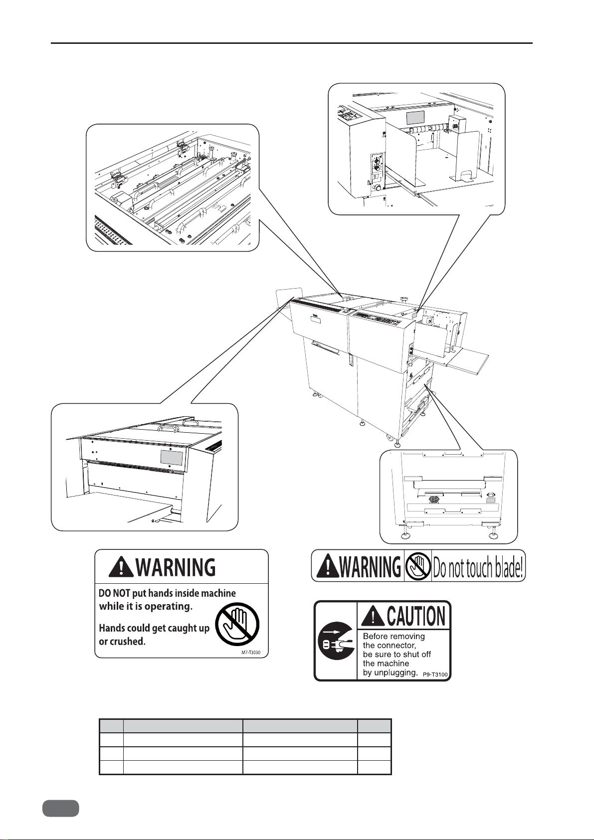
Warning Labels
2
1
1
1.
3
2.
3.
6
No. Part No. Name Q'ty
1 M7-T303* WARNING LABEL
2 L8-T107* WARNING LABEL 1
3 P9-T310* CAUTION LABEL 1
W5-Y1030
-0
2
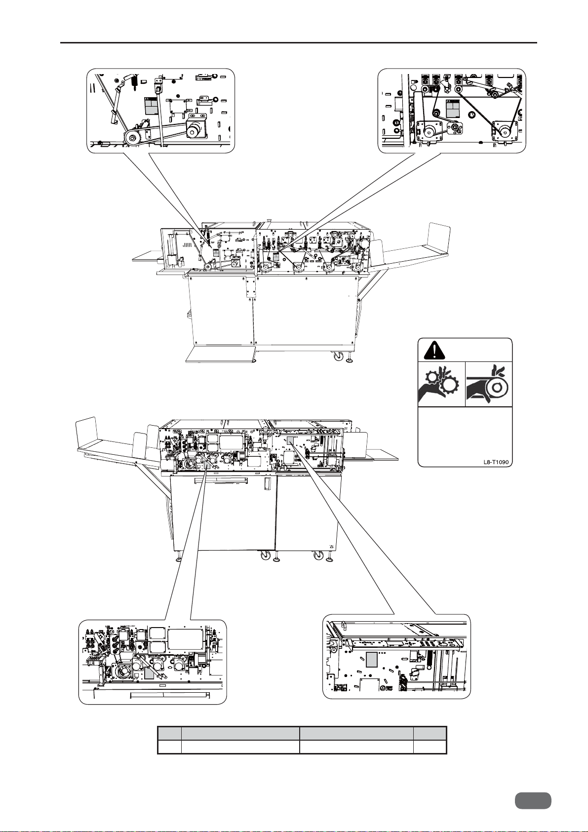
4. 4.
4.
WARNING
4.
Use caution when working
near movable parts.
Disconnect power before
servicing.
4.
No. Part No. Name Q'ty
4 L8-T109* WARNING LABEL 4
W5-Y1030
-0
7

5.
5.
5.
No. Part No. Name Q'ty
5 K9-T139* WARNING LABEL 3
8
W5-Y1030
-0
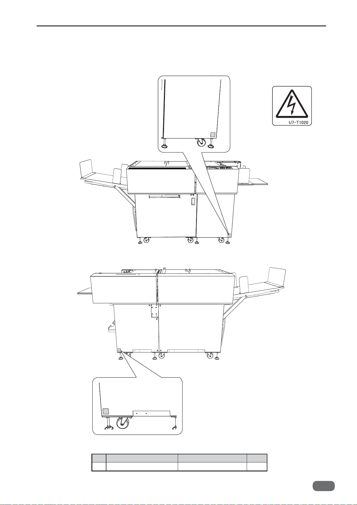
■
Labels of High-Voltage Warning
1. 1.
1.
No. Part No. Name Q'ty
1 U7-T102* WARNING LABEL 2
W5-Y1030
-0
9


Introduction
Operation in General
Mechanism
Adjustment
Maintenance Checks
1
2
3
4
5
Troubleshooting
HELP Mode
Others
PC Controller
6
7
8
9
10

Contents
Contents
Introduction
How to Use This Service Manual
Safety Instructions
Warning Labels
Labels of High-Voltage Warning
Chapter 1
1
Specifi cations
2
Part Names and Their Functions
3
Dimensions
Chapter 2
1
Paper Feed Section
2
Skew Adjust Section
3
Double-Feed Detection Section
4
CCD Section
5
Reject Section
6
Slot 1 Section (Margin Slitter Section)
7
Slot 2 Section
8
Slot 3 Section
9
Slot 4 Section
10
Gutter Section
11
Creaser Section
12
Cutter Section
13
Waste Box Section
14
Exit Tray
15
Main Drive Section
16
Exterior
17
Barcode
18
REG Mark
Chapter 3
....................................
............................
................................
Introduction
................................
..................................
Operation in General
........................
........................
.................................
...............................
...............................
...............................
...............................
...............................
.............................
...............................
.........................
......................................
.........................
.......................................
.......................................
....................................
Mechanism
..........
...........
........
..........
..
16
18
25
28
37
39
41
42
45
49
55
61
68
71
74
78
80
82
84
87
90
1
2
3
6
9
10
Slot 4 Section
11
Gutter Section
12
Creaser Section
13
Cutter Section
Paper Exit Section
14
Waste Box Section
15
Main Drive Section
16
Electrical System Section
17
Chapter 4
Exterior of the Machine
1
Paper Feed Section
2
Skew Adjust Section
3
Double-Feed Detection Section
4
CCD Section (option)
5
Reject Section
6
Slot 1 Section (Margin Slitter Section)
7
Slot 2 Section
8
Slot 3 Section
9
Slot 4 Section
10
Gutter Section
11
Creaser Section
12
Cutter Section
13
Main Drive Section
14
15
Adjustment procedure
Chapter 5
1
Guaranteeing Maintenance Cycle
2
Cleaning and Oiling
3
Periodic Maintenance Check List
4
Periodic Maintenance Sequences
...............................
..............................
............................
..............................
.........................
........................
........................
................
Adjustment
...................
.......................
.......................
.........
.....................
..............................
.
...............................
...............................
...............................
..............................
............................
..............................
........................
....................
Maintenance Checks
......
.......................
.......
......
152
158
160
163
168
170
172
184
198
201
208
209
210
211
212
214
216
218
220
224
228
231
237
240
240
241
246
1
Exterior
2
Paper Feed Section
3
Skew Adjust Section
4
Double-Feed Detection Section
5
CCD Section (option)
6
Reject Section
7
Slot 1 Section (Margin Slitter Section)
8
Slot 2 Section
9
Slot 3 Section
12
.......................................
.......................
.......................
.....................
..............................
...............................
...............................
W5-Y1030
-0
.........
.
96
104
120
124
127
129
134
140
145
Chapter 6
1
Troubleshooting
2
Conditions for the Error Detection
Major Cause and Preventive Action for the
3
Paper Jam
Troubleshooting
............................
......
..................................
266
286
290

Contents
Chapter 7
1
HELP Mode List
2
Accessing the HELP Mode
3
Finishing the HELP Mode
4
Setting the Other HELP Mode No.
5
Accessing the Service Personnel JOB
6
HELP Mode Description
Chapter 8
1
Position and Function of Electronic Parts
2
Service Personnel JOBs
3
Overall Wiring Layout
Chapter 9
Main Menu of PC Controller
1
2
Maintenance Menu
3
Data Folder
4
Maintenance
5
Confi rming the Version
HELP Mode
............................
...............
................
..................
Others
.................
.....................
PC Controller
.............
........................
.................................
................................
....................
......
..
292
294
294
294
294
295
368
390
395
404
406
409
410
420
1
W5-Y1030
-0
13


1
Chapter 1
Specifi cations .................................................................................16
1
2
Part Names and Their Functions ..................................................18
3
Dimensions .....................................................................................25
Introduction
(1) Appearance ..............................................................................18
(2) Paper Eject side ....................................................................... 19
(3) Paper Eject Side (Stacker Tray) ............................................... 20
(4) Inside ........................................................................................ 21
(5) Control panel ............................................................................22
(6) LCD panel ................................................................................ 24

Chapter 1 Specifi cations
1
Specifi cations
Product type Slitter/Cutter/Creaser Floor model
Feeding method Belt suction
Feed tray Elevator
Infeed document size Width: 210–370 mm (8.27–14.56 in)
Minimum fi nishing size Width: 48 mm (1.89 in)
Document weight Min: 110 gsm
Document type Coated, non-coated, laminated
Paper curl No curl (within 5 mm)
Feeder capacity 100 mm (3.93 in)
Speed 30 ppm: A4 LEF 2 cuts and 1 crease
Tolerance + /- 0.2 mm on fi nished size (Business cards: + /- 0.3 mm)
Number of slitters
Side margin slit width 3.2–55 mm (from the edge of a document)
Gutter slit width 5.0–15.0 mm
Gutter defl ector 2 gutter defl ectors
Max number of cuts on 1
document
Minimum cut length Lead edge margin: 3 mm
Maximum number of
creases on 1 document
Exit tray Drop down tray
Exit tray capacity 140 mm (5.51 in)
Card stacker capacity 60 mm (2.36 in)
Control panel 128 dots×64 dots LCD OK monitor
Panel languages Japanese, English, French, German, Italian, Spanish, Polish, Russian
Job programming On the control panel or on the PC controller software
Noise level Less than 80 db during a continuous operation
1
Model name DC-646
Length: 210–670 mm (8.27–26.37 in)
Length: 50 mm (1.97 in)
Max: 350 gsm
● Laminated stock or UV coated stock should be within the range
above including the lamination/UV coating.
● The crease tolerance depends on the number of creases on the
documents and their depths.
6 slitters (2 margin slitters and 4 center slitters are equipped as standard.)
● Waste strips wider than 15 mm come out on the exit tray.
Automatic control
25
Gutter cut between cards: 3 mm
Trail edge margin: 5 mm
20
16
W5-Y1030
-0
Chapter 1 Specifi cations
Model name DC-646
Standard functions PC controller software
80 job memory
Test feed
Air knife
Double feed detection
Fan register adjustment
Emergency stop switch
Waste box
Image shrinkage compensation (lengthwise)
Automatic job setup by reading Barcode *
Image drift compensation by reading REG mark *
Reject *
Card stacker *
PC arm mount *
Cleaning mode
*: Optional on 230V model
PC controller (USB connection: B-type connector)
Compatible OS:
Windows XP professional/home edition (x86 32bit only)
Windows Vista Ultimate/Business/Home basic/Home premium
Windows7 Ultimate/Professional/Home premium
Windows8 Professional/Enterprise
(Windows Vista/Windows7/Windows8: x86 32bit, x64 64bit)
Optional devices RTM-02 DC-646 Rotary Tool Module *
CPM-02 DC-646 Cross Tool Module
OPK-02 DC-646 Optional PCB Kit *
*: Standard on 230V(PRO) model
Power supply 100 VAC±10%, 50/60 Hz
Power consumption 100 V: current consumption 4.7 A , power consumption 430 W
Dimensions ● 230V
Weight 230V 115V 230V(PRO)
Safety standard UL
Operating temperature 10°C–30°C (50°F–86°C)
Operating humidity 40%RH–70%RH (No condensation)
Storing temperature 5°C–35°C (41°F–95°C)
Storing humidity 20%RH–70%RH (No condensation)
115 VAC, 50 Hz
230 VAC, 50/60 Hz
115 V: current consumption 4.0 A, power consumption 420 W
230 V: current consumption 1.9 A, power consumption 400 W
In use: 2310(W) × 765(D) × 1110(H) mm
Folded: 1650(W) × 765(D) × 1110(H) mm
● 115V/230V(PRO)
In use: 2310(W) × 1005(D) × 1110(H) mm
(90.94(W) × 39.56(D) × 43.70(H) in
Folded: 1650(W) × 1005(D) × 1110(H) mm
(64.96(W) × 39.56(D) × 43.70(H) in
Net weight
Gross weight
CE (Low Voltage Directive, Machinery Directive)
VCCI
FCC
270 kg
(595 lb)
335 kg
(738 lb)
280 kg
(617 lb)
345 kg
(760 lb)
1
285 kg
(628 lb)
350 kg
(771 lb)
1
The specifi cations are subject to change without prior notice.
W5-Y1030
-0
17
Chapter 1 Part Names and Their Functions
2
Part Names and Their Functions
2
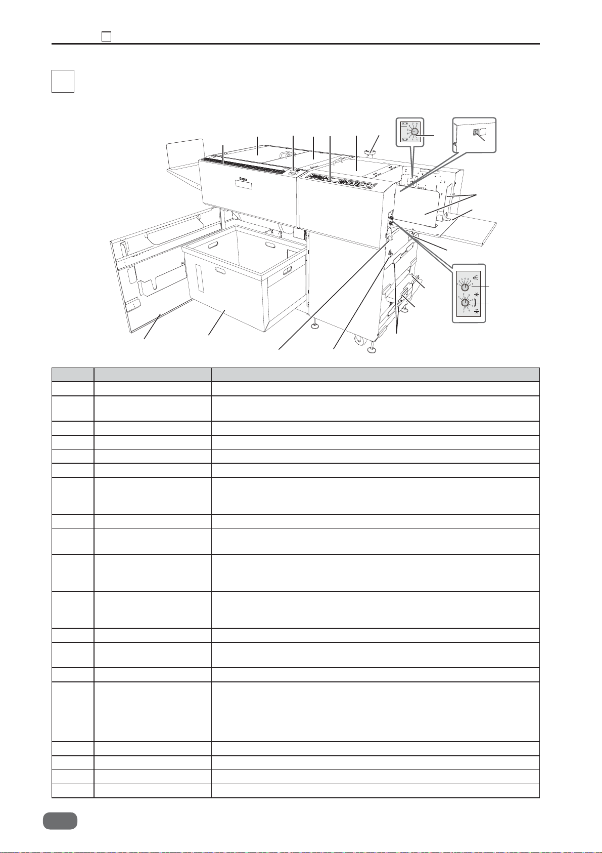
(1) Appearance
7
2
12
11
10
8
9
4
21
1
3
16
20
15
13
No. Name Function
1
Side guide (for feed tray)
2
PC arm mount
3 Feed tray Original document is placed here.
4 Level adjustment knob Adjusts the elevator height.
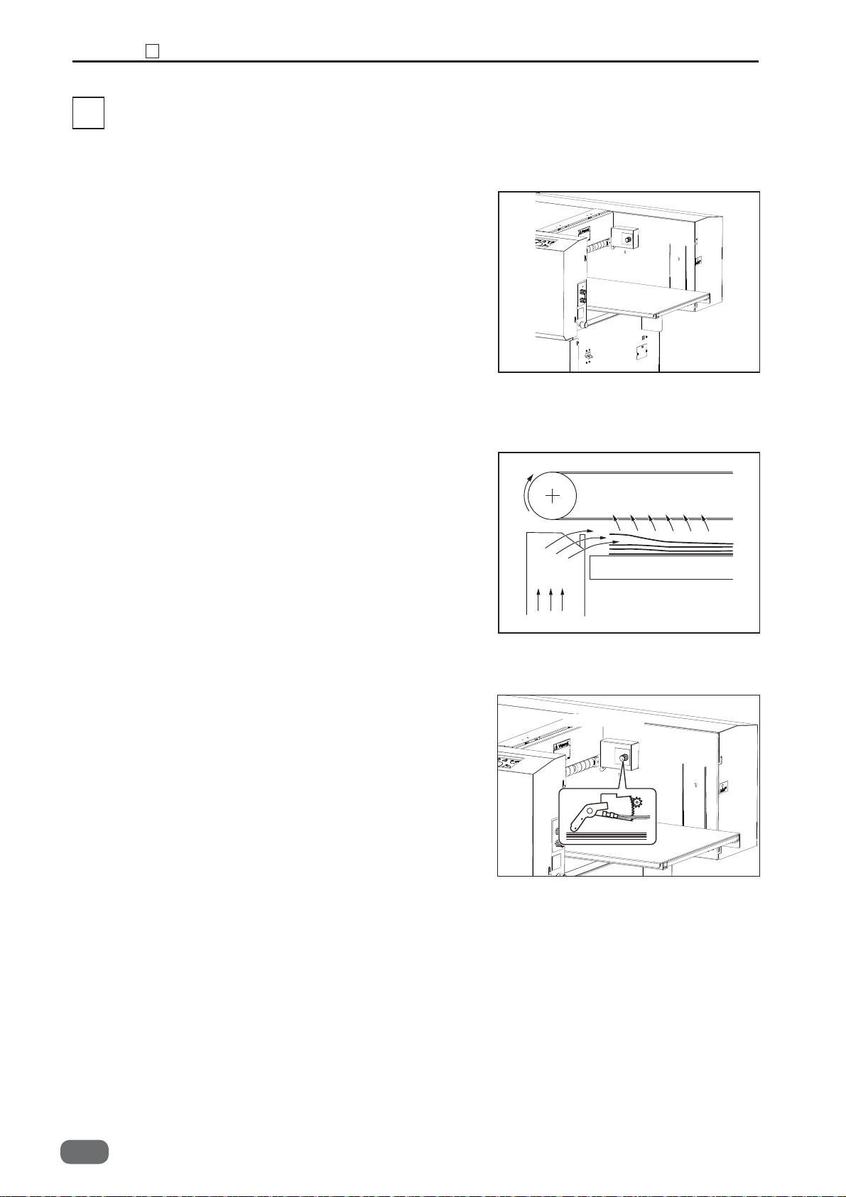
5
Airfl ow adjustment knob
6
Separator adjustment knob
7 Top cover 1 Open this to move the
8 Control panel Displays operations and status.
9
Emergency stop
switch
10 Top cover 2
11 Top cover 3 Open this to remove the paper jam from the cutter/crease/
12 Scale Measures the cut and slit position, and the fi nished product.
13 Front cover Open this to remove the waste box. When the cover is opened,
14 Waste box Receives pieces of waste paper.
15 Reject tray This is where the document comes when it is rejected due to
16 USB terminal Used for the connection to your computer on PC controller using.
17 Skew adjustment knob Adjusts the document skew.
18 Power switch Move this up/down to turn the power on/ off.
19
Module hanger Unused module can be hung on here.
14
17 18
Set this according to the document size.
Install a commercial monitor arm for putting the laptop computer.
(Optional on 230V model)
Adjusts airfl ow level.
Adjusts the distance between the separator and conveyance belt.
upper guide or to remove the paper jam
from the feed unit. When the cover is opened, machine stops
running by the interlock switch.
Press this to stop the machine in emergency. Turning the switch
to the right releases the emergency stop.
Open this to remove the paper jam from the slitter/optional module
area
or to replace the optional module
When the cover is opened, machine stops running by the interlock switch.
optional module or to replace the optional module.
cover is opened, machine stops running by the interlock switch.
machine stops running by the interlock switch.
double feed, barcode error, REG mark error, etc.
(Optional on 230V model)
DC-646 Reject Option is required for ejecting document to the
reject tray.
19
.
5
6
When the
18
W5-Y1030
-0
Chapter 1 Part Names and Their Functions
No. Name Function
20 AC inlet Connect the power cord here.
21 Elevator down switch Press this to lower the feed tray to the bottommost position.
2
1
1
No. Name Function
1 PC tray Place a desktop computer on this tray. (Optional on 230V model)
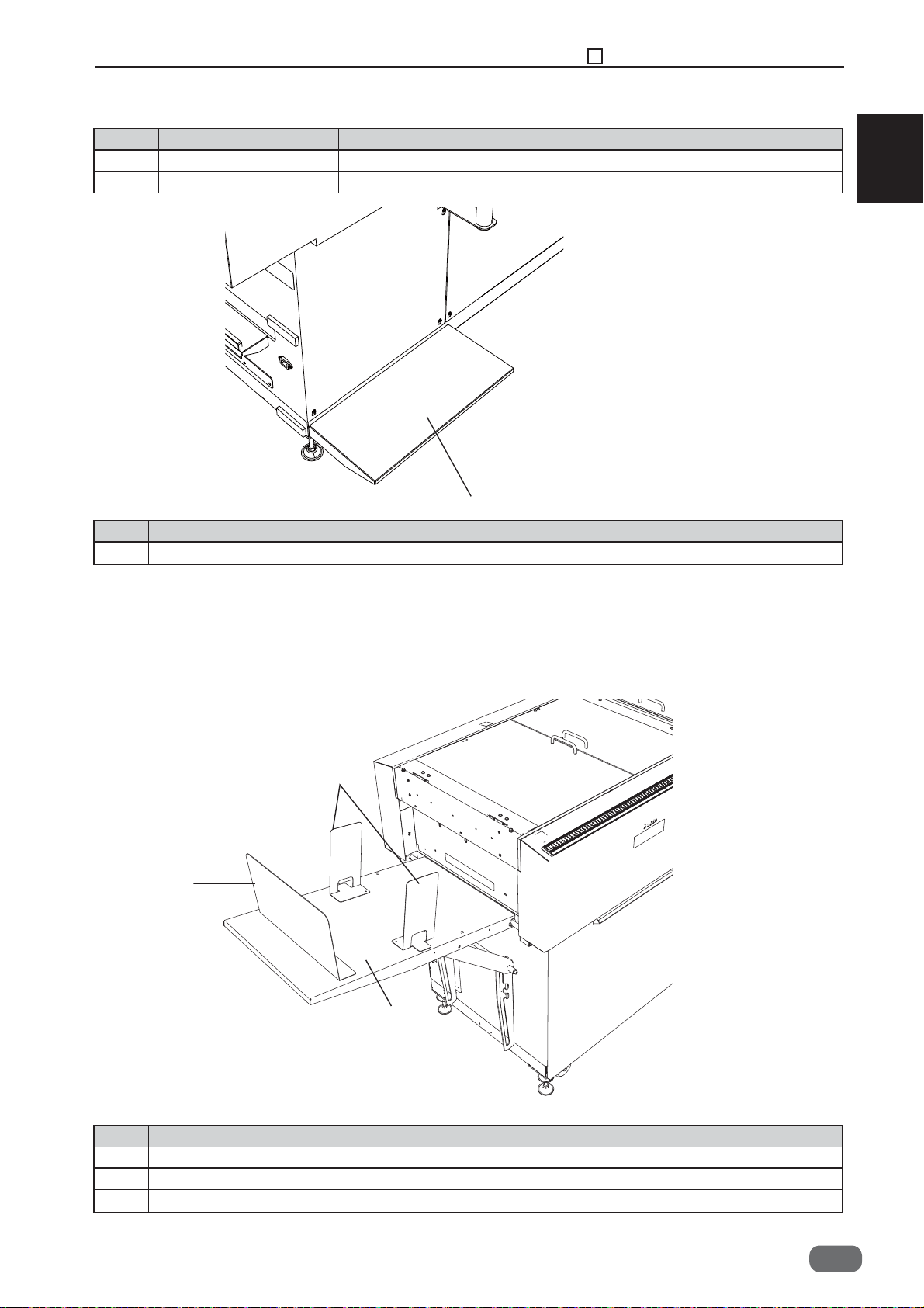
(2) Paper Eject side
2
3
1
No. Name Function
1 Exit tray Receives the fi nished products.
2
Side guide
3 Back guide Set this according to the document size.
(for exit tray)
Set this according to the document size.
W5-Y1030
-0
19
Chapter 1 Part Names and Their Functions
2
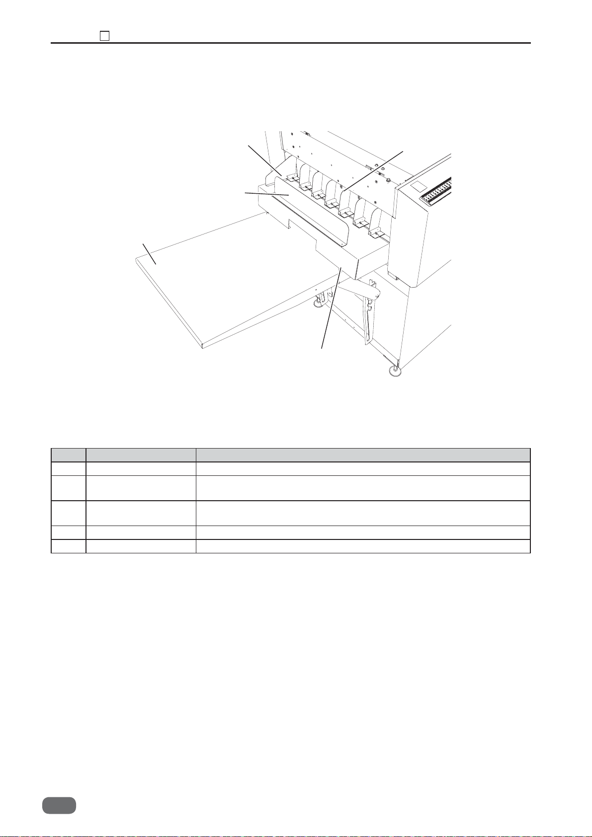
(3) Paper Eject Side (Stacker Tray)
2
3
5
1
4
No. Name Function
1 Guide Set this according to the card width. (Optional on 230V model)
2 Support guide
Set this when paper alignment is poor. (Optional on 230V model)
(for card stacker)
3 Stopper assy
Set this according to the card length. (Optional on 230V model)
(for card stacker)
4 Card stacker Receives the card-sized fi nished product. (Optional on 230V model)
5 Exit tray Receives the fi nished product.
20
W5-Y1030
-0
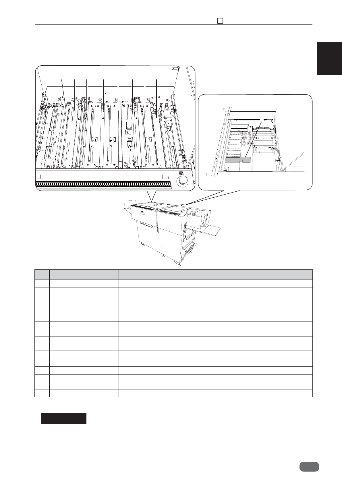
(4) Inside
Paper
ejection side
Inside of top cover 2, 3
32184567
Chapter 1 Part Names and Their Functions
Paper feed
side
2
1
Inside of top cover 1
9
No. Name Function
1 Margin slitter module Cuts off the both margins of operator’s side and non-operator’s side.
2 Standard module *1
Rotary tool module *2
*1: DC-646 115V
DC-646 230V
*2: DC-646 230V(PRO)
3 Center slitter module 1 Cuts parallel to the document feed direction
4 Center slitter module 2 Cuts parallel to the document feed direction. * You can also install
5 Gutter defl ector
6 Creaser module Creases perpendicularly to the document feed direction.
7 Cutter module Cuts perpendicularly to the document feed direction.
8 Reject This is where the document comes when it is rejected due to double
9 Upper guide Used to set the light weight document.
Conveys the document.
Perforates or scores parallel to the document feed direction
*
You can also install the center slitter module (optional) or cross
tool module (optional) here.
. * You can also install
the standard module or rotary tool module (optional) here.
the standard module or rotary tool module (optional) here.
Drops the margin cut off by the slitters into the waste box.
feed, barcode error, REG mark error, etc.
.
IMPORTANT
• When removing various modules of this machine, always re-set the module in the
sequential order indicated in the figure above. It is especially that the slitter module is
properly assembled, when setting it in the slot 2, 3, and 4 again.
• Slitter modules for DC-645 cannot be used in the DC-646.
W5-Y1030
-0
21
Chapter 1 Part Names and Their Functions
2
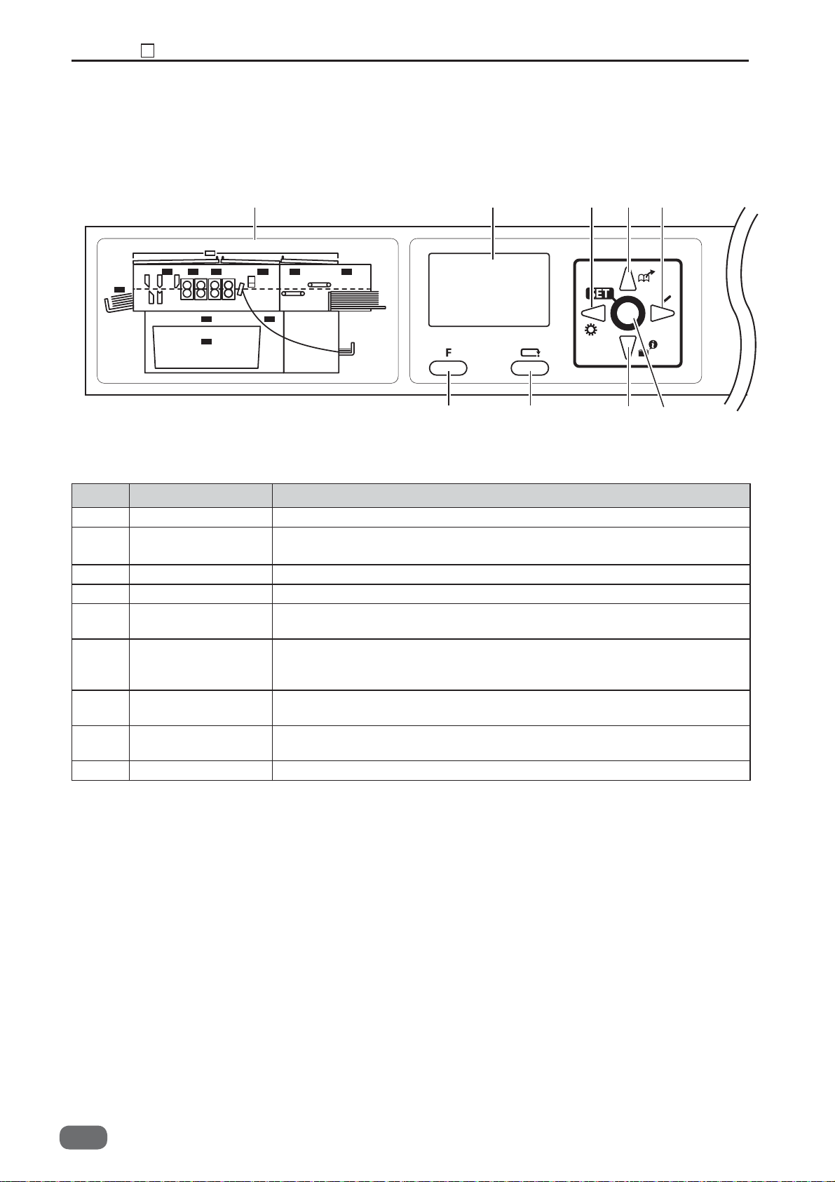
(5) Control panel
12
7 8
3456
No. Name Function
1 OK Monitor The LED of the error area fl ashes when detecting an error.
2 LCD panel Displays the status of the machine.
Displays the message when an error or paper jam occurs.
3 F key Switches to function selecting screen.
4 RETURN key Switches to the previous screen.
5 CURSOR (Up) key Press to move the cursor in an upper direction.
Press to retrieve the saved JOB.
6 CURSOR (Down)
key
Press to move the cursor in a lower direction.
Press to confi rm module setup and tool setup for cross tool module
and rotary tool module.
7 CURSOR (Left) key Press to move the cursor to the left.
Press to retrieve function setting.
8 CURSOR (Right)
key
Press to move the cursor to the right.
Press to save or overwrite a JOB.
9 SET key Press to fi x selection / entry.
9
22
W5-Y1030
-0
Chapter 1 Part Names and Their Functions
2
141310
1
11 12
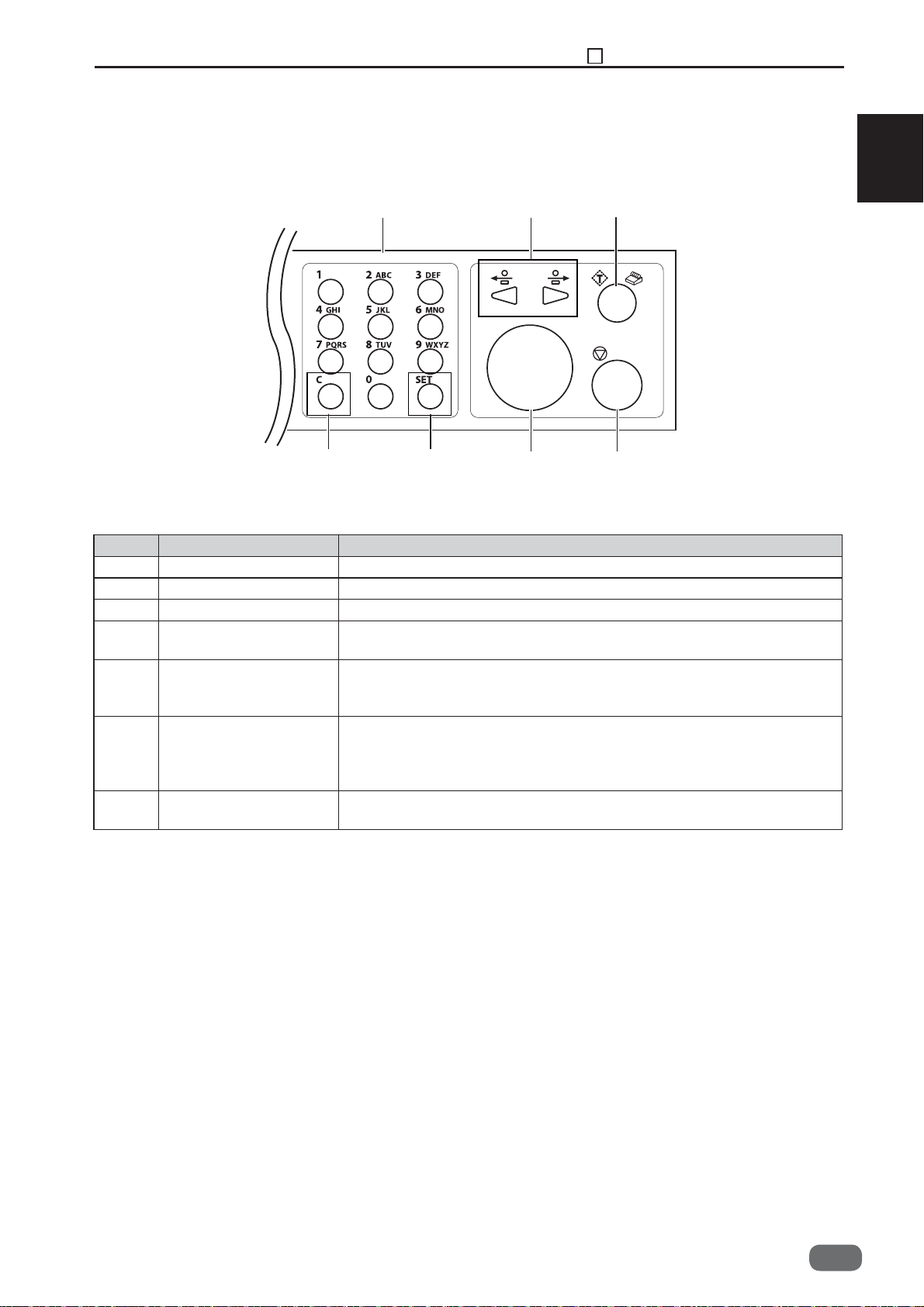
No. Name Function
10 NUMERIC key Press to enter JOB/values during manual programming.
11 CLEAR key Press to clear the count. Press to cancel manual programming.
12 SET key Press to fi x selection/entry.
13 JOG key Press to eject the document from the machine when paper jam
occurred.
14 TEST key
15 START key Press to start processing documents. The START key light turns
16 STOP key Press to return the current screen to the main screen or to stop
One (sheet) document is processed to test the current JOB details.
The processed document temporarily stops for a while at the
entrance of the card stacker for guide adjustment.
green when the machine is ready to process the document in this
machine. This key is inactive when the light is red. In this case,
the machine may be running or having an error.
processing.
15
16
W5-Y1030
-0
23
Chapter 1 Part Names and Their Functions
3
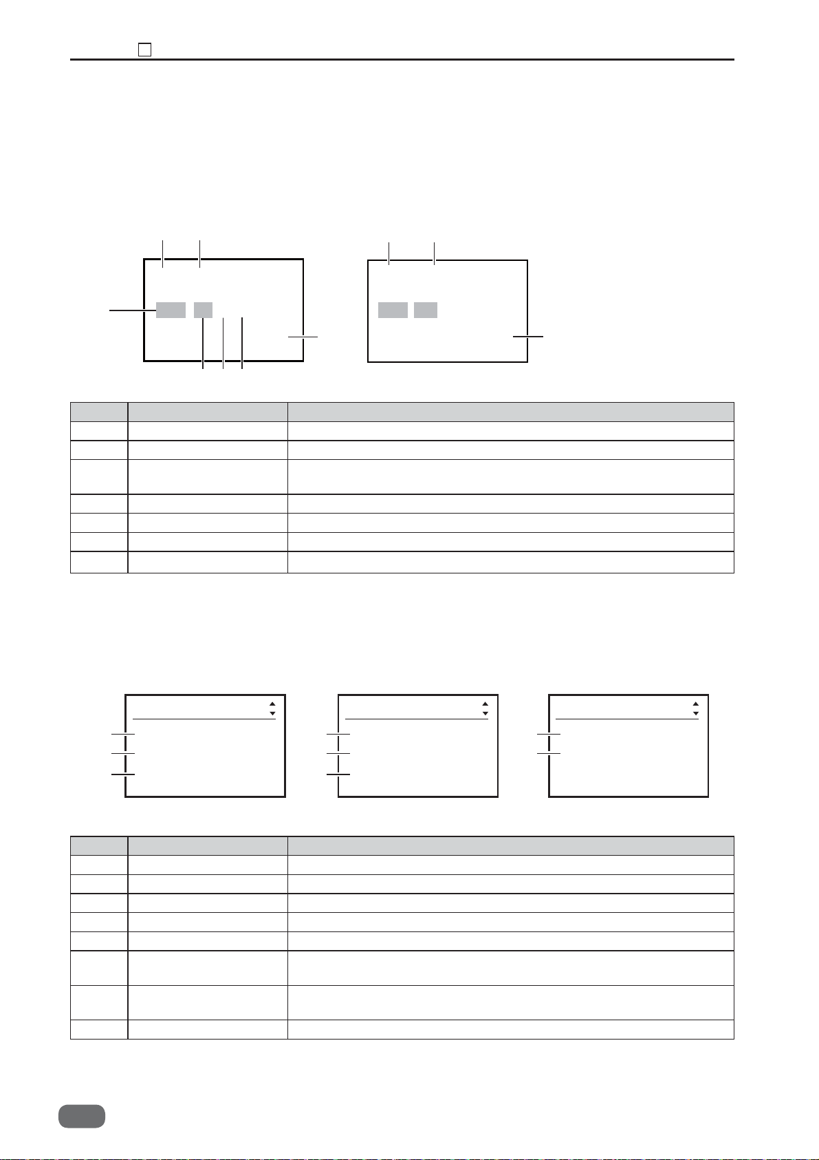
(6) LCD panel
● Standby screen
Continuous count
4
21
01:**********
RGB BC %
Sheets
67
5
↓
↓
↓
↓
9999
3
Batch count
1 2
REG BC
Sheets 999/999
3
No. Name Function
1 JOB No. Displays the JOB number currently selected.
2 JOB Name Displays the JOB name currently selected.
3 Counter Displays the number of document sheets processed with the JOB
currently set.
4 REG mark
REG is displayed when "REG mark reading" is ON.
5 Barcode BC is displayed when "barcode reading" is ON.
6 % % is displayed when "Apply shrinkage" is set in "Settings3.
7 is displayed when "Adjust All" is set.
↓
↓
↓
↓
↓
↓
↓
↓
● ‘Select menu’ screen
Select menu Select menu
1
2
3
Retrieve JOB
Enter JOB
Settings1
4
5
6
Settings2
Settings3
Adjust All
No. Name Function
1 Retrieve JOB Retrieves saved JOB.
2 Enter JOB Enters and changes JOB.
3 Settings1 Changes functions of the machine.
4 Settings2 Changes functions of the machine.
5 Settings3 Changes functions of the machine.
6 Adjust All Corrects the document position in vertical and horizontal direction
against the JOB set.
7 Cleaning mode Retrieves Cleaning mode to clean conveyance belt / conveyance
roller.
8 Return Returns to standby screen.
Select menu
Cleaning mode
7
Return
8
24
W5-Y1030
-0
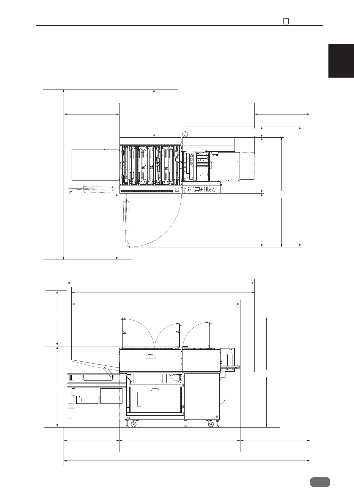
3
Dimensions
Chapter 1 Dimensions
3
* With the PC arm amount attached
Dimensions in ( ): DC-646 115V, DC-646 230V(PRO)
1
2650mm
1000mm
800mm
2570mm
2510mm
800mm800mm
(240mm)
765mm
(1745mm)
1505mm
745mm
800mm
1110mm
2310mm
1650mm
3250mm
1540mm
800mm800mm
W5-Y1030
-0
25


Chapter 2
Operation in General
2
1
Paper Feed Section
1. Description
2. Operation
3. Operation of Each Part
2
Skew Adjust Section
1. Description
2. Operation
3. Operation of Each Part
3
Double-Feed Detection Section
1. Description
2. Operation
3. Operation of Each Part
4
CCD Section
1. Description
2. Operation
5
Reject Section
1. Description
2. Operation
3. Operation of Each Part
6
Slot 1 Section (Margin Slitter Section)
1. Description
2. Operation
3. Slitter Blade
4. Operation of Each Part
7
Slot 2 Section
1. Description
2. Operation
Slot 3 Section
8
1. Description
2. Operation
3. Slitter Blade
4. Operation of Each Part
9
Slot 4 Section
1. Description
2. Operation
3. Slitter Blade
4. Operation of Each Part
....................................
....................................
....................................
...................................
....................................
....................................
....................................
....................................
....................................
....................................
...........................
..................................
....................
.........................
..................................
....................
............
..................................
....................
..................................
.................................
..................................
....................
..................................
.................................
....................
.................................
..................................
.................................
..................................
.................................
....................
.................................
..................................
.................................
....................
....
28
28
28
28
37
37
37
37
39
39
39
40
41
41
41
42
42
42
42
45
45
45
45
46
49
49
49
55
55
55
55
56
61
61
61
61
62
Gutter Section
10
1. Description
2. Operation
3. Operation of Each Part
11
Creaser Section
1. Description
2. Operation
3. Operation of Each Part
Cutter Section
12
1. Description
2. Operation
3. Operation of Each Part
13
Waste Box Section
1. Description
2. Operation of Each Part
Exit Tray
14
1. Description
2. Operation of Each Part
15
Main Drive Section
1. Description
2. Operation of Each Part
16
Exterior
1. Description
2. Operation
3. Operation of Each Part
17
Barcode
1. Description
18
REG Mark
1. Description
..........................................
.........................................
.................................
..................................
....................................
...............................
..................................
....................................
.................................
..................................
....................................
..................................
.........................................
..................................
..................................
..................................
....................................
..................................
.......................................
..................................
....................
....................
....................
..........................
....................
....................
............................
....................
....................
68
68
68
68
71
71
71
71
74
74
74
74
78
78
78
80
80
80
82
82
82
84
84
84
84
87
87
90
90
Chapter 2 Paper Feed Section
1
Paper Feed Section
1
1. Description
Paper feed section feeds the paper into the
machine after separating each sheet of paper by
air knife. This is done through the operation of the
belt suction mechanism and the air blow duct
mechanism.
2. Operation
Air blow duct mechanism blows the compressed
air to the paper from the front side to create some
gap between the papers. The separated paper is
transferred when the shutter solenoid and the
feed motor provided in the belt suction
mechanism are turned ON.
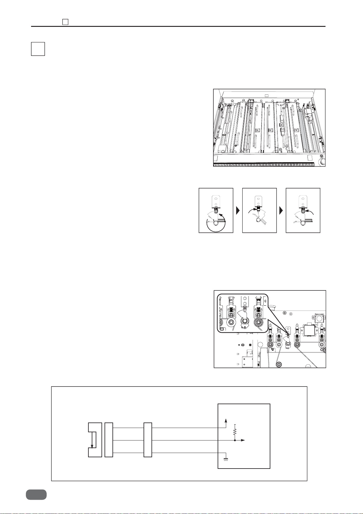
3. Operation of Each Part
I. Level Sensor 1 (SN002)
<Operation>
• Detect the top of the paper on the feed tray
When the feed tray rises to the extent that the
actuator is lifted up by the paper, the sensor
comes to the “light blocked” state.
Once the topmost sheet of paper is detected, the
rising motion of the feed tray is stopped.
• Detect the low level of paper
The actuator comes down as the paper
level gets low until the sensor comes to the “light
through” state. Once the sensor comes to the
“light through” state, the feed tray rises until the
sensor comes to the “light blocked” state. “E02”
(elevator error) appears on the display if the
topmost paper sensor does not switch to the
“light blocked” state within 30 seconds after the
transmission of feed tray go-up command.
Level Sensor1
28
W5-Y1030
-0

<Circuit diagram>
Red Red Red
1
2
Blue Blue Blue
3
3
4
5
SN002
1
White Yellow Yellow
2
3
2. Level Sensor 2 (SN003)
<Operation>
• Detect the top of the paper on the feed tray
When the feed tray rises to the extent that the
actuator is lifted up by the paper, the sensor
comes to the “light blocked” state.
Once the topmost sheet of paper is detected,
the rising motion of the feed tray is stopped.
Only the topmost sheet of the paper is detected
by the level sensor 2.
• Detect the low level of paper.
The level sensor 2 detects only the topmost
sheet of paper and the level sensor 1 detects
the low level of paper.
CN12-20
21
22
Chapter 2 Paper Feed Section
Main PCB Unit
W5-V510*
5V
5V
Light not transmitted: 5V
Light transmitted: 0V
1
Level Sensor2
2
<Circuit diagram>
FM003
Red
1
Yellow Yellow Yellow
2
Blue Blue Blue
3
Red Red
1
2
3
Main PCB Unit
W5-V510*
5V
3
4
5
CN12-23
24
25
5V
Light not transmitted: 5V
Light transmitted: 0V
W5-Y1030
-0
29

Chapter 2 Paper Feed Section
1
3. Paper Tray Sensor (SN001)
<Operation>
This sensor detects paper presence or nonpresence on the feed tray. When papers are on
the feed tray, the sensor detects the reflecting
light. When no paper is on the feed tray, the
sensor does not detect the refl ecting light.
Confi rm the sensor state in HELP-12.
<Circuit diagram>
Red Red
SN001
3
White
2
1
1
2
Blue Blue
3
White
CN12-11
12
13
Paper Tray Sensor
Main PCB Unit
W5-V510*
5V
5V
Light not transmitted: 0V
Light transmitted: 5V
4. Elevator Upper Switch (SW001)
<Operation>
If the topmost sheet of paper cannot be detected,
and the paper feed plate continues to go up, the
air suction module is pulled away from the
elevator upper limit switch to come to the “OFF”
state.
The elevator upper limit switch stops the machine
operation immediately once it comes to the “OFF”
state.
Elevator Upper Switch
30
W5-Y1030
-0

Chapter 2 Paper Feed Section
1
5. Elevator Lower Switch 1, 2 (SW003, SW004)
<Operation>
As the feed plate goes up, the angle is pulled
away from the elevator lower limit switch to come
to the “ON” state. As the feed plate goes
down to reach the lower limit, the angle pushes
the switch actuator to trigger the “OFF” state.
“E02” (elevator error) appears on the display
if the angle does not push the elevator lower
limit switch actuator within 30 seconds after the
transmission of the feed plate go-down command.
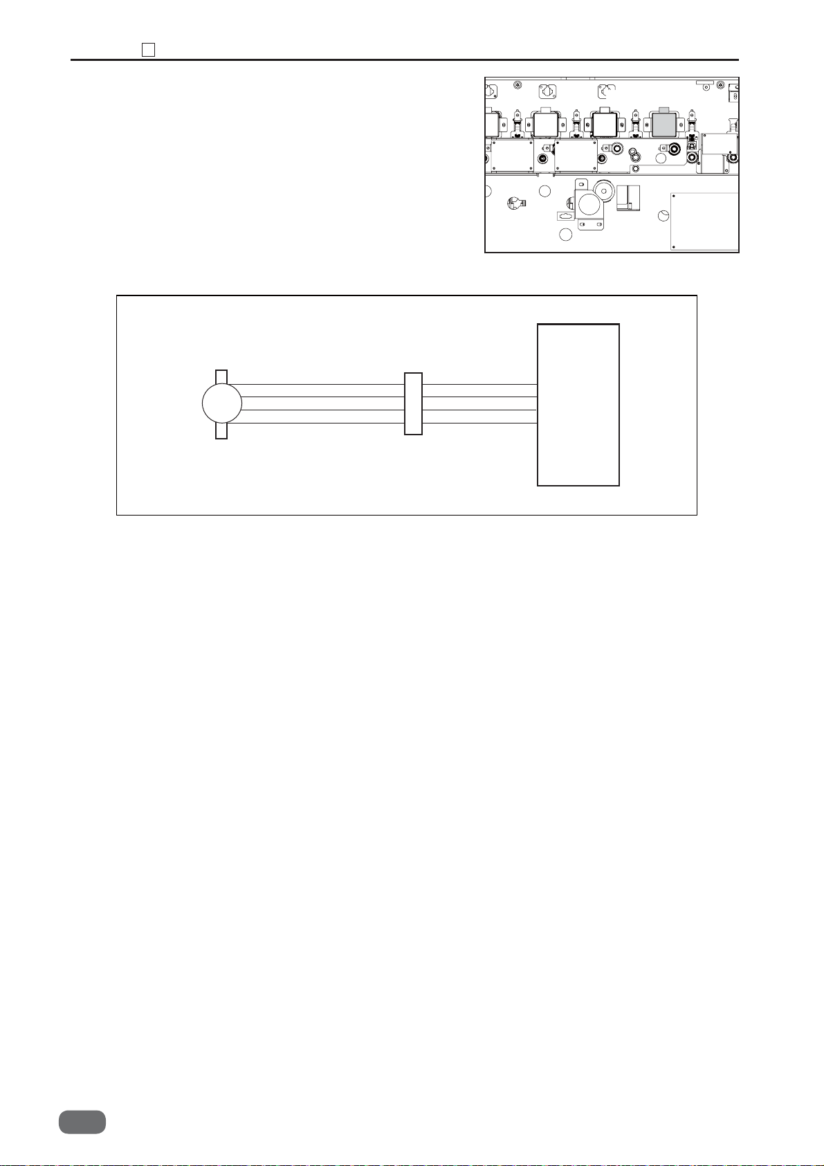
6. Elevator Motor (MT003)
<Operation>
Elevator motor rotation let the feed tray move up
and down.
Elevator Lower Switch1
Elevator Lower Switch2
2
Elevator Motor
<Circuit diagram>
SW003
SW001
Purple
Purple
Red Red
Red
2
1
Main PCB Unit
W5-V510*
5V
Purple
Purple
MT003
M
CN12-15
16
CN4
CN4
Drive2 PCB Unit
W5-V550*
1
2
Red
1
Blue
2
SW004
Red
Red Red Red
2
1
1
Blue Blue
2
CN5-1
2
W5-Y1030
-0
31

Chapter 2 Paper Feed Section
1
7. Elevator Down Switch (SW013)
<Operation>
Normally the feed plate goes up and down
automatically. However, it may be lowered by the
elevator down switch as required, including the
case of paper jam.
<Circuit diagram>
SW013
Yellowish green
Yellowish green
Green
1
Green
2
1
2
Green
Green
CN12-18
19
Elevator Down Switch
Main PCB Unit
W5-V510*
5V
ON : 0V
OFF : 5V
8. Suction Solenoid (SL001)
<Operation>
The suction solenoid is turned ON as the level
sensor is turned ON and the paper feed is ready.
Then, the valve opens to suck up the paper.
The valve is closed by the timer after the
transferred paper passes through the PPS2.
<Circuit diagram>
SL001
M
Red
Red
Red
1
Red
2
7
8
Red
Red
Suction Solenoid
Drive 2 PCB Unit
W5-V550*
24V
Red
CN2-5
5
Red
6
6
32
W5-Y1030
-0

9. Separate Solenoid (SL002)
<Operation>
When the adjustment is set at 1 through 7, the paper
•
separator is raised by turning on the solenoid until
the paper end passes through the separator position
to prevent the double feed. After the paper passes
through,
the separator is lowered so that it will not hinder
the paper transfer.
• When the adjustment is set over 7 (i.e. When it is
turned clockwise to the maximum), the screw pushes
the actuator of the solenoid switch to cancel the paper
separator function.
• Paper separator solenoid is also canceled
when the paper jam takes place.
10. Solenoid ON/OFF Switch (SW002)
<Operation>
Paper separator height can be altered by turning
the paper separator dial from 1 (max.) to 7
(min.). When the dial is turned beyond 7, the
paper separator stops its function and goes
down to the lowest position.
Chapter 2 Paper Feed Section
Solenoid ON/OFF
Switch
1
Separate Solenoid
2
<Circuit diagram>
SW002
M
SL002
Red
Red
Drive 2 PCB Unit
W5-V550*
24V
1
2
Red
Red
CN2-7
Red
7
8
Red
8
W5-Y1030
-0
33

Chapter 2 Paper Feed Section
1
11. Suction Fan (FM001)
<Operation>
Suction fan sucks up the loaded paper by per
sheet to the feed belt for conveyance at the time
of paper feed.
<Circuit diagram>
Red Red Red Red
Black Black Black
1
2
FM001
Suction Fan
Drive 2 PCB Unit
W5-V550*
24V
5
6
1
2
CN2-1
Black
2
34
W5-Y1030
-0

12. Blow Out Fan1 (FM002),
Blow Out Fan2 (FM003)
<Operation>
Two blow out fans blow the air to separate papers
from foreside at the time of paper feed.
<Circuit diagram>
FM002
Red
Black
1
2
Red
1
Black
2
3
4
Red
Black
Chapter 2 Paper Feed Section
Drive 2 PCB Unit
W5-V550*
24V
CN2-3
4
1
Blow Out Fan1
Blow Out Fan2
2
FM003
Red
Black
1
2
W5-Y1030
-0
35

Chapter 2 Paper Feed Section
13
1
. Feed Belt Motor (MT002)
<Operation>
Feed belt motor controls the feed belt driving.
<Circuit diagram>
Feed Motor
MT002
M
14. PPS1 (
Green
Orange
Yellow
White
Photo-emission
1
3
4
6
SN006/
Photo-receiving
1
2
3
4
SN007)
<Operation>
While the light goes through at the PPS sensor,
LED on the control panel and the start key light
up in red. “PLEASE SET PAPER” appears on the
display as the start key is pressed. While the light
is blocked at the PPS sensor, the start key lights
up in green.
* Wipe off the dirt or contamination, if any, on the
PPS sensor by some rag.
Drive 1 PCB Unit
W5-V540*
Green
Orange
Yellow
White
CN3-1
2
3
4
1
2
3
4
Transmitting
Receiving
36
<Circuit diagram>
SN006
SN007
W5-Y1030
Transmitting
Receiving
-0
Main PCB Unit
W5-V510*
5V
1
3
1
2
3
Red
Orange
Red
White
Blue
Red
1
Orange
2
Red
1
White
2
Blue
3
CN12-1
2
3
4
5
5V
Light not transmitted: 5V
Light transmitted: 0V

2
Skew Adjust Section
1. Description
The paper, separated by air suction mechanism,
is transmitted in the corrected angular position,
since it is abutted to the frame by the slantingly
arranged conveyer belts as it is sent the next
process.
2. Operation
In the skew adjust section, the fan starts to rotate
as the start key is turned ON. The conveyer belt
starts to rotate just as the air suction module belt
starts its rotation. It is stopped by the timer.
Chapter 2 Skew Adjust Section
2
2
3. Operation of Each Part
1. Skew Motor (MT004)
<Operation>
Skew motor controls the skew belt driving.
<Circuit diagram>
MT004
M
White
Green
Yellow
Orange
6
4
3
1
White
Green
Yellow
Orange
Skew Motor
Drive 1 PCB Unit
W5-V540*
White
7
6
5
4
8
7
6
5
Green
Yellow
Orange
CN3-8
7
6
5
W5-Y1030
-0
37

Chapter 2 Skew Adjust Section
2
2. Fan Register (FM005)
<Operation>
Fan register suctions a paper to the skew belt for
conveyance.
<Circuit diagram>
FM005
Red
Brown
Black
1
2
3
Red
Brown
Black
1
2
3
Reject Open Motor
12
13
14
Red
Brown
Black
Drive 2 PCB Unit
W5-V550*
CN2-12
13
14
3. PPS2 (Photo-emission
SN008/
Photo-receiving
SN009)
<Operation>
• Detect the top edge of the paper
PPS detects the presence or non-presence of paper
by the “light-through” or the light-blocked” state
of the PPS photo-receiving sensor by means of
receiving from the PPS photo-emitting sensor.
Then, mis-feed or paper jam is detected by the
skew adjust section.
If the light path between the PPS sensors is
blocked by the paper (or by the dirt on the PPS
sensor) when the power supply is turned ON,
“J3” (FEED ERROR) appears on the display.
* Wipe off the dirt or contamination, if any, on the
PPS sensor by some rag.
<Circuit diagram>
SN008
Transmitting
1
3
Red
Orange
Red
1
Orange
2
CN12-6
7
Transmitting
Receiving
Main PCB Unit
W5-V510*
5V
38
SN009
W5-Y1030
Receiving
-0
1
2
3
Red
Yellow
Blue
Red
1
Yellow
2
Blue
3
8
9
10
5V
Light not transmitted: 5V
Light transmitted: 0V

Chapter 2 Double Feed Detection Section
3
Double-Feed Detection Section
3
1. Description
The double-feed detection sensor is provided
between the air suction module and the skew
adjust section (beside the PPS2).
An ultrasonic sensor is used, which can deal with
wider range of paper types compared with
conventional mechanical sensor or photo-micro
sensor. Also, no adjustment for fi tting it to the
particular type of paper, and no input of the
paper thickness are required in the ultrasonic
sensor.
Receiving
TransmittingTransmitting
2. Operation
Whenever the ultrasonic sensor detects double
feed, the rejection bar opens to send out the
double-fed paper to the reject tray.
When the double-feed is repeated for a preset
number of times, “DOUBLE FEED” appears on
the display, and the machine stops the operation.
2
W5-Y1030
-0
39

Chapter 2 Double Feed Detection Section
3
3. Operation of Each Part
1. Double Feed Sensor (
SN004)
<Operation>
Whenever the ultrasonic sensor detects doublefeed, the rejection bar opens to send out the
double-fed paper to the reject tray. In addition, if
the double-feed is repeated for a preset number of
times, “DOUBLE FEED” appears on the display,
and the machine stops the operation.
<Circuit diagram>
Transmission SN005, Receiving
TransmittingTransmitting
Receiving
Receiving
SN005
SN004
Transmit
Receiving
Red
Black
Red
Black
Transmit PCB Unit
Red
2
1
2
1
CN1-1
White
Red
White
P9-V303*
2
CN1-2 4
CN3-2 4
2
Receive PCB Unit
P9-V305*
Brown
Blue
CN1-2CN2-1
2
Brown
1
Blue
5
White
Blue Blue
White
6
7
24V Power Supply Unit
Main PCB Unit
W5-V510*
CN12-27
28
40
W5-Y1030
-0

4
CCD Section
1. Description
This section reads the barcode and REG mark by
CCD.
2. Operation
On the JOB using REG mark or barcode, PPS3
works to assure the correct CCD reading by
temporarily stopping the paper run at the place of
PPS3 and slows it. The paper conveyance speed
will be accelerated after the CCD reading.
Chapter 2 CCD Section
4
2
1. PPS3 (
Photo-emission
SN010/
Photo-receiving
SN011)
<Operation>
•
PPS detects the presence or non-presence of paper
by the “light-through” or the light-blocked” state of
the PPS photo-receiving sensor by means of receiving
from the PPS photo-emitting sensor.
•
On the JOB using REG mark or barcode, PPS3
works to assure the correct CCD reading by
temporarily
stopping the paper run at the place of
PPS3 and slows it.
• In the operation without REG mark or barcode,
PPS 3 detects the timing of passing paper.
<Circuit diagram>
Red
Pink
Red
Gray
Blue
1
2
1
2
3
SN010
SN011
Transmit
Receiving
1
3
1
2
3
Red
Orange
Red
Gray
Blue
CN19-1
CN13-1
Transmitting
Receiving
Main PCB Unit
W5-V510*
5V
2
5V
2
Light not transmitted: 5V
3
Light transmitted: 0V
W5-Y1030
-0
41
Chapter 2 Reject Section
5
Reject Section
5
1. Description
If the CCD detects the error in reading the
barcode or the register mark, or the double-feed,
the rejection bar in front of the Slot 1 opens to
drop the paper into the reject tray.
2. Operation
When you turn off and on (restart) the machine,
the rejection bar makes a turn. The reject HP
sensor detects “light through” → “light blocked”
→ “light through” state by the edges of the sensor
plate on the rejection bar, and the rejection bar
stops. At this time, the rejection bar is closed and
this is home position.
If the CCD reading error of the barcode or the
register mark, or the double-feed takes place, the
rejection bar opens. The reject HP sensor detects
“light through” → “light blocked” → “light blocked”
state, and the rejection bar moves to the point of
“light through” state and reject motor stops. When
the rejection bar returns to the home position, the
reject HP sensor detects “light through” → “light
blocked” → “light through” state, and the rejection
bar moves to the point of “light through” state and
the reject motor stops.
Home position
reject bar: closed
Reject bar: open
Home position
reject bar: closed
3. Operation of Each Part
I. Rejection Home Position Sensor (SN012)
<Operation>
The rejection home position sensor detects the
position of the rejection bar while it returns to the
home position.
<Circuit diagram>
1
2
3
SN012
1
2
3
Red
Yellow
Blue
Reject HP Sensor
5V
CN11-7
8
9
Main PCB Unit
W5-V510*
5V
Light not transmitted: 5V
Light transmitted: 0V
42
W5-Y1030
-0

Chapter 2 Reject Section
5
2. PPS 8 Sensor (
receiving
SN016)
Photo-emission
SN015/
Photo-
<Operation>
• PPS detects the presence or non-presence of paper
by the “light-through” or the light-blocked” state of
the PPS photo-receiving sensor by means of receiving
from the PPS photo-emitting sensor.
• This sensor detects paper jam in reject section.
<Circuit diagram>
Red
Orange
Red
Gray
Blue
1
2
3
4
5
SN015
SN016
Transmit
Receiving
1
3
1
2
3
Red
Orange
Red
Gray
Blue
CN19-7
CN13-10
11
12
Main PCB Unit
W5-V510*
5V
8
5V
Light not transmitted:5V
Light transmitted:0V
2
W5-Y1030
-0
43

Chapter 2 Reject Section
5
3. Reject Open Motor (MT005)
<Operation>
Reject open motor controls gating operation of
reject bar.
<Circuit diagram>
Reject Open Motor
Drive 2 PCB Unit
W5-V550*
M
MT005
Brown Brown
Black Black
1
2
CN7-5
6
44
W5-Y1030
-0

Chapter 2 Slot 1 Section(Margin Slitter Section)
6
Slot 1 Section (Margin Slitter Section)
6
1. Description
The margin slitter is provided one each on both
sides to cut the paper along the traveling direction
by means of the upper and lower rotary blades.
The cut-off margin is dropped into the waste box.
Margin Slitter Module
2
2. Operation
The lead screw is turned by means of the
stepping motor to cause the margin slitter to
move from the home position by the specifi ed
amount of pulse.
3. Slitter Blade
The slitter blades are constructed so that the
lower blade of the slitter is tilted relative to the
paper feed direction. This makes the upper and
lower slitter blades contact at only one point to
maintain the clean cut even after the slitter blade
has worn out.
W5-Y1030
-0
45

Chapter 2 Slot 1 Section(Margin Slitter Section)
6
4. Operation of Each Part
1. Module Detection 1 Sensor (SN024)
<Operation>
Module detection 1 sensor detects the presence
or non-presence of margin slitter module by
sensing the margin slitter module by the photo-
-micro sensor.
<Circuit diagram>
Red
White
Blue
1
2
3
White
SN024
1
2
3
Red
Blue
Module Detection1 Sensor
Main PCB Unit
W5-V510*
5V
CN17-1
2
3
5V
Light not transmitted: 5V
Light transmitted: 0V
2. Slitter 1 Home Position Sensor (SN037)
<Operation>
Slitter 1 HP sensor detects the home position
of the margin slitter 1 unit by the photo-micro
sensor, and controls the margin slitter 1 position
based on the sensor position.
<Circuit diagram>
SN037
3
1
2
Red
White
Blue
1
2
3
Red
White
Blue
CN11-1
Slitter1 HP Sensor
Slitter Drive
PCB Unit
5V
W5-V520*
5V
2
Light not transmitted: 5V
Light transmitted: 0V
3
46
W5-Y1030
-0

Chapter 2 Slot 1 Section(Margin Slitter Section)
3. Slitter 2 Home Position Sensor (SN038)
<Operation>
Slitter 2 HP sensor detects the home position
of the margin slitter 2 unit by the photo-micro
sensor, and controls the margin slitter 2 unit
position based on the sensor position.
<Circuit diagram>
SN038
3
1
2
Red
White
Blue
1
2
3
Red
White
Blue
CN11-16
17
18
6
Slitter2 HP Sensor
Slitter Drive
PCB Unit
5V
W5-V520*
5V
Light not transmitted: 5V
Light transmitted: 0V
2
4. Slitter Motor 1 (MT007)
<Operation>
Slitter motor 1 controls the margin slitter 1
position based on the home position by means of
rotating the lead shaft.
<Circuit diagram>
Brown
1
Yellow
2
Green
3
White
4
MT007
M
Brown
Yellow
Green
White
Slitter Motor1
Slitter Drive
PCB Unit
W5-V520*
CN6-1
2
3
4
W5-Y1030
-0
47
Chapter 2 Slot 1 Section(Margin Slitter Section)
6
5. Slitter Motor 2 (MT008)
<Operation>
Slitter motor 2 controls the margin slitter 2
position based on the home position by means of
rotating the lead shaft.
<Circuit diagram>
MT008
M
Brown
Yellow
Green
White
1
3
4
6
Brown
Yellow
Green
White
Slitter Motor2
Slitter Drive
PCB Unit
W5-V520*
CN7-1
2
3
4
48
W5-Y1030
-0

7
Slot 2 Section
1. Description
Slot 2 Section is used to meet the special cutting
requirements which cannot be dealt with by the
cutter module or the slitter module. (Transfer
module is attached to the standard model. Rotary
tool module (RTM), Cross tool module (CPM) and
Optional slitter module (OSM) are option.)
CPM RTM OSM
Chapter 2 Slot 2 Section
7
2
2. Operation
1. Module Detection 2 Sensor (SN025)
<Operation>
Option module detection sensor identifi es the type
of optional module by one of the detecting sensors
1, 2, 3 or 4, or by the combination of these sensors
to implement the control required for the
particular optional module attached.
<Circuit diagram>
1
2
3
SN025
1
2
3
Red
Yellow
Blue
CN17-4
Module Detection2 Sensor
Main PCB Unit
W5-V510*
5V
5V
5
Light not transmitted: 5V
Light transmitted: 0V
6
W5-Y1030
-0
49

Chapter 2 Slot 2 Section
7
2. Module Detection 3 Sensor (SN026)
<Operation>
Option module detection sensor identifi es the type
of optional module by one of the detecting sensors
1, 2, 3 or 4, or by the combination of these sensors
to implement the control required for the particular
optional module attached.
<Circuit diagram>
SN026
1
2
3
4
5
6
Red
Gray
Blue
CN17-7
Module Detection3 Sensor
Main PCB Unit
W5-V510*
5V
5V
8
Light not transmitted: 5V
Light transmitted: 0V
9
3. Module Detection 4 Sensor (SN027)
<Operation>
Option module detection sensor identifi es the type
of optional module by one of the detecting sensors
1, 2, 3 or 4, or by the combination of these sensors
to implement the control required for the particular
optional module attached.
<Circuit diagram>
Red
Green
Blue
SN027
1
2
3
7
8
9
CN17-10
11
12
Module Detection4 Sensor
Main PCB Unit
U7-V510*
5V
5V
Light not transmitted: 5V
Light transmitted: 0V
50
W5-Y1030
-0

4. Module Detection 5 Sensor (SN028)
<Operation>
Option module detection sensor identifi es the type
of optional module by one of the detecting sensors
1, 2, 3 or 4, or by the combination of these sensors
to implement the control required for the particular
optional module attached.
<Circuit diagram>
Red
White
Blue
SN028
1
2
3
10
11
12
CN17-13
14
15
Chapter 2 Slot 2 Section
7
Module Detection5 Sensor
Main PCB Unit
W5-V510*
5V
5V
Light not transmitted: 5V
Light transmitted: 0V
2
5. Slitter 3 Home Position Sensor (SN039)
<Operation>
Slitter 3 HP sensor detects the home position of
the slitter 1 located on the non-operator's side by
the photo-micro sensor, and controls the slitter 1
position based on the sensor position.
<Circuit diagram>
SN039
3
1
2
Red
Yellow
Blue
1
2
3
Red
Yellow
Blue
CN11-4
Slitter3 HP Sensor
Slitter Drive PCB Unit
W5-V520*
5V
5V
5
6
Light not transmitted: 5V
Light transmitted: 0V
W5-Y1030
-0
51

Chapter 2 Slot 2 Section
7
6. Slitter 4 Home Position Sensor (SN040)
<Operation>
Slitter 4 HP sensor detects the home position
of the slitter 2 located on the operator's side by
the photo-micro sensor, and controls the slitter 2
position based on the sensor position.
<Circuit diagram>
Red
Yellow
Blue
1
2
3
SN040
3
1
2
Red
Yellow
Blue
CN11-19
20
21
Slitter4 HP Sensor
Slitter Drive PCB Unit
W5-V520*
5V
5V
Light not transmitted: 5V
Light transmitted: 0V
7. Slitter Motor 3 (MT009)
<Operation>
Slitter Motor 3 controls the option unit position
based on the amount of pulse from its home
position by means of rotating the lead shaft.
<Circuit diagram>
Black
MT009
M
1
Yellow
3
Green
4
White
6
Slitter Motor3
Slitter Drive
PCB Unit
W5-V520*
5
6
7
8
CN6-5
6
7
8
52
W5-Y1030
-0

Chapter 2 Slot 2 Section
7
7. Slitter Motor 4 (MT010)
<Operation>
Slitter Motor 4 controls the option unit position
based on the amount of pulse from its home
position by means of rotating the lead shaft.
<Circuit diagram>
Black
1
Yellow
3
MT010
M
Green
4
White
6
Slitter Motor4
2
Slitter Drive
PCB Unit
W5-V520*
CN7-5
6
7
8
W5-Y1030
-0
53

Chapter 2 Slot 2 Section
7
9. Jump Motor 1(MT022)(option)
<Operation>
Jump motor controls the RTM driving when the
RTM is installed in the slot 2.
<Circuit diagram>
MT022
Jump Motor1
Drive 4 PCB Unit
W5-V570*
10. PPS4
M
Brown
Black
(Photo-emission
SN052/
1
2
Photo-receiving
Brown
Black
SN053)
<Operation>
•
PPS detects the presence or non-presence of paper
by the “light-through” or the light-blocked” state of
the PPS photo-receiving sensor by means of receiving
from the PPS photo-emitting sensor.
• This sensor detects paper jam in the slot 2.
<Circuit diagram>
CN4-1
2
Transmitting
Receiving
54
SN052
SN053
W5-Y1030
-0
Transmitting
Receiving
Main PCB Unit
W5-V510*
5V
1
3
1
2
3
Red
Pink
Red
Gray
Blue
1
3
1
2
3
Red
Orange
Blue
Gray
Blue
CN19-3
CN13-4
4
5V
5
Light not transmitted: 5V
Light transmitted: 0V
6

8
Slot 3 Section
1. Description
Two center slitters are provided each on both
sides to cut the paper in the traveling direction by
means of the rotary blades arranged vertically
side by side.
Chapter 2 Slot 3 Section
8
2
When performing special cutting which cannot be
processed by the slitter module, install the RTM
in the slot 3 to perform special cutting. (Slitter
module is installed in the standard model.)
2. Operation
The lead screw is turned by means of the
stepping motor to cause the center slitters to
move from the home position by the specifi ed
distance.
3. Slitter Blade
The slitter blades are constructed so that the
lower blade of the slitter is tilted relative to the
paper feed direction. This makes the upper and
lower slitter blades contact at only one point to
maintain the clean cut even after the slitter blade
has worn out.
RTM
W5-Y1030
-0
55

Chapter 2 Slot 3 Section
8
4. Operation of Each Part
1. Module Detection 6 Sensor (SN029)
<Operation>
Option module detection sensor identifi es the type
of optional module by one of the detecting sensors
1, 2, 3 or 4, or by the combination of these sensors
to implement the control required for the particular
optional module attached.
<Circuit diagram>
Red
Yellow
Blue
1
2
3
SN029
1
2
3
Red
Yellow
Blue
CN17-16
17
18
Module Detection6 Sensor
Main PCB Unit
W5-V510*
5V
5V
Light not transmitted: 5V
Light transmitted: 0V
2. Module Detection 7 Sensor (SN030)
<Operation>
Option module detection sensor identifi es the type
of optional module by one of the detecting sensors
1, 2, 3 or 4, or by the combination of these sensors
to implement the control required for the particular
optional module attached.
<Circuit diagram>
SN030
1
2
3
Red
Gray
Blue
4
5
6
Red
Gray
Blue
CN17-19
20
21
Module Detection7 Sensor
Main PCB Unit
W5-V510*
5V
5V
Light not transmitted: 5V
Light transmitted: 0V
56
W5-Y1030
-0

3. Module Detection 8 Sensor (SN031)
<Operation>
Option module detection sensor identifi es the type
of optional module by one of the detecting sensors
1, 2, 3 or 4, or by the combination of these sensors
to implement the control required for the particular
optional module attached.
<Circuit diagram>
SN031
1
2
3
Red
Green
Blue
7
8
9
Red
Green
Blue
CN17-22
23
24
Chapter 2 Slot 3 Section
Module Detection8 Sensor
Main PCB Unit
W5-V510*
5V
5V
Light not transmitted: 5V
Light transmitted: 0V
8
2
4. Module Detection 9 Sensor (SN032)
<Operation>
Option module detection sensor identifi es the type
of optional module by one of the detecting sensors
1, 2, 3 or 4, or by the combination of these sensors
to implement the control required for the particular
optional module attached.
<Circuit diagram>
SN032
1
2
3
Red
White
Blue
10
11
12
Red
White
Blue
CN17-25
26
27
Module Detection9 Sensor
Main PCB Unit
W5-V510*
5V
5V
Light not transmitted: 5V
Light transmitted: 0V
W5-Y1030
-0
57

Chapter 2 Slot 3 Section
8
5. Slitter 5 Home Position Sensor (SN041)
<Operation>
Slitter 5 HP sensor detects the home position of the
center slitter 5 unit by the photo-micro sensor, and
controls the center slitter 5 unit position based on
the sensor position.
<Circuit diagram>
Red
Gray
Blue
4
5
6
SN041
3
1
2
Red
Gray
Blue
CN11-7
Slitter5 HP Sensor
Slitter Drive PCB Unit
W5-V520*
5V
5V
8
Light not transmitted: 5V
Light transmitted: 0V
9
6. Slitter 6 Home Position Sensor (SN042)
<Operation>
Center slitter 6 HP sensor detects the home position
of the center slitter 6 unit by the photo-micro sensor,
and controls the center slitter 6 unit position based
on the sensor position.
<Circuit diagram>
Red
Gray
Blue
SN042
3
1
2
Red
Gray
Blue
4
5
6
CN11-22
23
24
Slitter6 HP Sensor
Slitter Drive
PCB Unit
5V
W5-V520*
5V
Light not transmitted: 5V
Light transmitted: 0V
58
W5-Y1030
-0

7. Slitter Motor 5 (MT011)
<Operation>
Slitter motor 5 controls the center slitter 5 unit
position based on the home position by means of
rotating the lead shaft.
<Circuit diagram>
Chapter 2 Slot 3 Section
Slitter Motor5
Slitter Drive
PCB Unit
W5-V520*
8
2
Gray
1
Yellow
3
Green
4
White
6
MT011
M
Gray
Yellow
Green
White
8. Slitter Motor 6 (MT012)
<Operation>
Slitter motor 6 controls the center slitter 6 position
based on the home position by means of rotating
the lead shaft.
<Circuit diagram>
9
10
11
12
CN6-9
10
11
12
Slitter Motor6
MT012
M
Gray
Yellow
Green
White
Slitter Drive
PCB Unit
W5-V520*
1
3
4
6
Gray
Yellow
Green
White
CN7-9
10
11
12
W5-Y1030
-0
59

Chapter 2 Slot 3 Section
8
9. Jump Motor 2 (MT023)(option)
<Operation>
Jump motor controls the RTM driving when the
RTM is installed in the slot 3.
<Circuit diagram>
MT023
Jump Motor2
Drive 4 PCB Unit
W5-V570*
10. PPS5 (
M
Brown
Black
Photo-emission
SN054/
1
2
Photo-receiving
Brown
Black
SN055)
<Operation>
PPS detects the presence or non-presence of paper
•
by the “light-through” or the light-blocked” state of
the PPS photo-receiving sensor by means of receiving
from the PPS photo-emitting sensor.
• This sensor detects paper jam in slitter section.
<Circuit diagram>
CN4-3
4
Transmitting
Receiving
60
SN054
SN055
W5-Y1030
-0
Transmit
Receiving
5V
Main PCB Unit
1
3
1
2
3
Red Red
Pink
Red
Gray
Blue
1
3
1
2
3
CN19-5
Orange 6
CN13-7
Red
Gray
Blue
5V
8
9
U7-V510*
5V
Light not transmitted: 5V
Light transmitted: 0V

9
Slot 4 Section
1. Description
Two center slitters are provided each on both
sides to cut the paper in the traveling direction by
means of the rotary blades arranged vertically
side by side.
Chapter 2 Slot 4 Section
9
2
When performing special cutting which cannot be
processed by the slitter module, install an option
module in the slot 4 to perform special cutting.
(Slitter module is installed in the standard model.)
2. Operation
The lead screw is turned by means of the
stepping motor to cause the center slitters to
move from the home position by the specifi ed
distance.
3. Slitter Blade
The slitter blades are constructed so that the
lower blade of the slitter is tilted relative to the
paper feed direction. This makes the upper and
lower slitter blades contact at only one point to
maintain the clean cut even after the slitter blade
has worn out.
RTM
W5-Y1030
-0
61

Chapter 2 Slot 4 Section
9
4. Operation of Each Part
1. Module Detection 10 Sensor (SN033)
<Operation>
Option module detection sensor identifi es the type
of optional module by one of the detecting sensors
1, 2, 3 or 4, or by the combination of these sensors
to implement the control required for the particular
optional module attached.
<Circuit diagram>
Red
Yellow
Blue
13
14
15
SN033
1
2
3
Red
Yellow
Blue
CN17-28
29
30
Module Detection10 Sensor
Main PCB Unit
W5-V510*
5V
5V
Light not transmitted: 5V
Light transmitted: 0V
62
W5-Y1030
-0

2. Module Detection 11 Sensor (SN034)
<Operation>
Option module detection sensor identifi es the type
of optional module by one of the detecting sensors
1, 2, 3 or 4, or by the combination of these sensors
to implement the control required for the particular
optional module attached.
<Circuit diagram>
SN034
1
2
3
Red
Gray
Blue
16
17
18
Red
Gray
Blue
CN17-31
32
33
Chapter 2 Slot 4 Section
Module Detection11 Sensor
Main PCB Unit
W5-V510*
5V
5V
Light not transmitted: 5V
Light transmitted: 0V
9
2
3. Module Detection 12 Sensor (SN035)
<Operation>
Option module detection sensor identifi es the type
of optional module by one of the detecting sensors
1, 2, 3 or 4, or by the combination of these sensors
to implement the control required for the
particular optional module attached.
<Circuit diagram>
SN035
1
2
3
Red
Green
Blue
19
20
21
Red
Green
Blue
CN17-34
35
36
Module Detection12 Sensor
Main PCB Unit
W5-V510*
5V
5V
Light not transmitted: 5V
Light transmitted: 0V
W5-Y1030
-0
63

Chapter 2 Slot 4 Section
9
4. Module Detection 13 Sensor (SN036)
<Operation>
Option module detection sensor identifi es the type
of optional module by one of the detecting sensors
1, 2, 3 or 4, or by the combination of these sensors
to implement the control required for the particular
optional module attached.
<Circuit diagram>
Red
White
Blue
22
23
24
SN036
1
2
3
Red
White
Blue
CN17-37
38
39
Module Detection13 Sensor
Main PCB Unit
W5-V510*
5V
5V
Light not transmitted: 5V
Light transmitted: 0V
5. Slitter 7 Home Position Sensor (SN043)
<Operation>
Slitter 7 HP sensor detects the home position of
the center slitter 7 unit by the photo-micro sensor,
and controls the center slitter 7 unit position
based on the sensor position.
<Circuit diagram>
SN043
3
1
2
Red
Black
Blue
7
8
9
Red
Black
Blue
CN11-10
11
12
Slitter7 HP Sensor
Slitter Drive PCB Unit
W5-V520*
5V
5V
Light not transmitted: 5V
Light transmitted: 0V
64
W5-Y1030
-0

Chapter 2 Slot 4 Section
9
6. Slitter 8 Home Position Sensor (SN044)
<Operation>
Center slitter 8 HP sensor detects the home
position of the center slitter 8 unit by the photomicro sensor, and controls the center slitter 8 unit
position based on the sensor position.
<Circuit diagram>
SN044
3
1
2
Red
Black
Blue
7
8
9
Red
Black
Blue
CN11-25
26
27
Slitter8 HP Sensor
Slitter Drive PCB Unit
W5-V520*
5V
5V
Light not transmitted: 5V
Light transmitted: 0V
2
7. Slitter Motor 7 (MT013)
<Operation>
Slitter motor 7 controls the center slitter 7 unit
position based on the home position by means of
rotating the lead shaft.
<Circuit diagram>
Orange
1
Yellow
2
Green
3
White
4
MT013
M
1
3
4
6
Slitter Motor7
Slitter PCB Unit
W5-V530*
CN3-1
2
3
4
W5-Y1030
-0
65

Chapter 2 Slot 4 Section
9
8. Slitter Motor 8 (MT014)
<Operation>
Slitter motor 8 controls the center slitter 8 position
based on the home position by means of rotating
the lead shaft.
<Circuit diagram>
MT014
M
Orange
Yellow
Green
White
1
3
4
6
Orange
Yellow
Green
White
Slitter Motor8
Slitter PCB Unit
W5-V530*
CN3-1
2
3
4
9. Jump Motor3 (MT024)(option)
<Operation>
Jump motor 3 controls the RTM driving when the
RTM is installed in the slot 4.
<Circuit diagram>
MT024
M
Brown
Black
1
2
Brown
Black
Jump Motor3
Drive 4 PCB Unit
W5-V570*
CN4-5
6
66
W5-Y1030
-0

Chapter 2 Slot 4 Section
9
10. PPS6-1,PPS6-2 (
Photo-receiving
SN058, SN059)
Photo-emission
SN056, SN057/
<Operation>
PPS detects the presence or non-presence of paper
•
by the “light-through” or the light-blocked” state of
the PPS photo-receiving sensor by means of receiving
from the PPS photo-emitting sensor.
• This sensor detects paper jam in slitter section.
<Circuit diagram>
Red
Orange
Red
White
Blue
1
2
1
2
3
SN056
SN058
Transmit
Receiving
1
3
1
2
3
Red
CN19-9
Orange 10
CN14-1
Red
White
Blue
Transmitting
Receiving
2
Main PCB Unit
5V
2
3
W5-V510*
5V
Light not transmitted: 5V
Light transmitted: 0V
SN057
SN059
Transmit
Receiving
5V
1
3
1
2
3
Red
Orange
Red
Yellow
Blue
3
4
4
5
6
Red
Orange
Red
Yellow
Blue
CN19-11
12
CN14-4
5
6
5V
Light not transmitted: 5V
Light transmitted: 0V
W5-Y1030
-0
67

Chapter 2 Gutter Section
10
Gutter Section
10
1. Description
The gutter section works to drop the gutter area
of the paper cut off by the center slitter into the
waste box.
2. Operation
The lead screw is turned by means of the
stepping motor to cause the gutter unit to move
from the home position by the specifi ed distance.
3. Operation of Each Part
1. Gutter 1 Home Position Sensor (SN045)
<Operation>
Gutter 1 HP sensor detects the gutter unit 1 home
position by the photo-micro sensor, and controls the
gutter unit 1 position based on the sensor position.
<Circuit diagram>
Red
White
Blue
SN045
3
1
2
1
2
3
CN11-13
14
15
Gutter1 HP Sensor
Slitter Drive PCB Unit
W5-V520*
5V
5V
Light not transmitted: 5V
Light transmitted: 0V
68
W5-Y1030
-0

Chapter 2 Gutter Section
10
2. Gutter 2 Home Position Sensor (SN046)
<Operation>
Gutter 2 HP sensor detects the gutter unit 2
home position by the photo-micro sensor, and
controls the gutter unit 2 position based on the
sensor position.
<Circuit diagram>
Red
White
Blue
SN046
3
1
2
1
2
3
CN11-28
29
30
Gutter2 HP Sensor
Slitter Drive PCB Unit
W5-V520*
5V
5V
Light not transmitted: 5V
Light transmitted: 0V
2
3. Gutter Motor 1 (MT015)
<Operation>
Gutter motor 1 controls the gutter unit position
based on the specifi ed distance from the home
position by means of rotating the lead shaft.
<Circuit diagram>
Purple
1
Yellow
3
MT015
M
Green
4
White
6
Gutter Motor1
Slitter PCB Unit
W5-V530*
CN3-5
Purple
5
Yellow
6
Green
7
White
8
6
7
8
W5-Y1030
-0
69

Chapter 2 Gutter Section
10
4. Gutter Motor 2 (MT016)
<Operation>
Gutter motor 2 controls the gutter unit position
based on the specifi ed distance from the home
position by means of rotating the lead shaft.
<Circuit diagram>
Purple
1
Yellow
3
MT016
M
Green
4
White
6
Gutter Motor2
Slitter PCB Unit
W5-V530*
Green
White
CN3-5
6
7
8
Purple
5
Yellow
6
7
8
70
W5-Y1030
-0

11
Creaser Section
1. Description
Creaser module contains the lower blade having
a concave (recessed) section and the upper
blade having a convex (projected) section. The
creaser unit works to crease the paper
perpendicularly to its traveling direction.
2. Operation
The sensor plate provided coaxially with the cam
detects the top dead center of the upper blade to
control the DC motor. The lower blade also can
move up and down by a cam. The height of the
lower blade is set by the DC motor with an
encoder, and is specifi ed relative to the lower
blade’s bottom dead center at which the sensor
plate is provided. The crease depth is
determined in this way.
Chapter 2 Creaser Section
11
2
3. Operation of Each Part
Crease Upper Home Position Sensor
1.
<Operation>
Crease upper home position sensor detects the top
dead center of the creaser upper blade by
sensing the light-blocking plate attached to the
creaser upper blade driving cam shaft by means
of the photo-micro sensor.
<Circuit diagram>
SN019
Red
1
Gray
2
Blue
3
Brown
1
Red
2
Orange
3
(SN019)
Brown
1
Red
2
Orange
3
CN9-7
Crease Up HP Sensor
Main PCB Unit
W5-V510*
5V
5V
8
Light not transmitted: 5V
Light transmitted: 0V
9
W5-Y1030
-0
71

Chapter 2 Creaser Section
11
2. Crease Lower Home Position Sensor (SN020)
<Operation>
Crease lower home position sensor detects the
bottom dead center of the crease lower blade by
sensing the light-blocking plate attached on the cam
shaft which adjusts the crease depth by means of
the photo-micro sensor.
<Circuit diagram>
SN020
Red
1
Purple
2
Blue
3
13
14
15
Green
Black
Brown
13
14
15
Green
Black
Brown
CN10-1
Crease Low HP Sensor
Main PCB Unit
W5-V510*
5V
5V
2
Light not transmitted: 5V
3
Light transmitted: 0V
3. Creaser Lower Blade Encoder Sensor (SN021)
<Operation>
Creaser lower blade encoder sensor adjusts the
crease depth in three levels from the lower limit
position by reading out the encoder attached to
the crease depth adjustment motor by means of
the photo-micro sensor.
<Circuit diagram>
Red
Yellow
Blue
SN021
1
2
3
Red
Yellow
Blue
1
2
3
CN10-4
Crease Encoder Sensor
Main PCB Unit
W5-V510*
5V
5V
5
Light not transmitted: 5V
6
Light transmitted: 0V
72
W5-Y1030
-0

Chapter 2 Creaser Section
11
4. Crease Lower Motor (MT020)
<Operation>
Crease lower motor rotates the encoder attached
in the crease lower motor to adjust the crease
depth in three steps.
<Circuit diagram>
MT020
M
Brown
Black
1
2
Brown
Black
Crease Low Motor
2
Drive 2 PCB Unit
W5-V550*
CN7-3
4
5. Crease Motor (MT019)
<Operation>
Crease motor controls the crease upper blade up
and down operation.
<Circuit diagram>
MT019
M
Red
Blue
1
2
Red
Blue
Crease Motor
Drive 2 PCB Unit
W5-V550*
CN6-3
4
W5-Y1030
-0
73

Chapter 2 Cutter Section
12
Cutter Section
12
1. Description
The “Guillotine type” cutter module is provided in
which the lower blade is fi xed while the upper
blade moves up and down to cut the paper
perpendicularly to the traveling direction.
2. Operation
The rotating motion of the DC motor is
transformed into the reciprocating motion of the
upper blade by means of crank mechanism.
A sensor is provided at the top dead center of the
blade stroke, which works to apply the brake on
the blade movement at every reciprocating cycle
to make it stop.
3. Operation of Each Part
1. Cutter Home Position Sensor 1 (SN017)
<Operation>
Cutter HP sensor 1 detects the blade bottom
dead positions by sensing the light-blocking plate
linked to the movement of rotary blade by means
of the photo-micro sensor.
<Circuit diagram>
SN017
Red
3
Yellow
2
Blue
1
Purple
7
Gray
8
White
9
7
8
9
Purple
Gray
White
CN9-1
Cutter HP1 Sensor
Main PCB Unit
W5-V510*
5V
5V
2
Light not transmitted: 5V
Light transmitted: 0V
3
74
W5-Y1030
-0

2. Cutter Home Position 2 Sensor (SN018)
<Operation>
Cutter HP 2 sensor detects the blade top dead
positions by sensing the light-blocking plate
linked to the movement of rotary blade by
means of the photo-micro sensor.
<Circuit diagram>
10
11
12
Black
Red
Blue
SN018
Red
3
Green
2
Blue
1
10
11
12
Black
Red
Blue
CN9-4
Main PCB Unit
W5-V510*
5V
5V
5
Light not transmitted: 5V
Light transmitted: 0V
6
Chapter 2 Cutter Section
Cutter HP2 Sensor
12
2
3. Cutter Motor (MT018)
<Operation>
Cutter motor controls the upper blade up and
down operation.
<Circuit diagram>
MT018
M
Red
Blue
1
2
Red
Blue
Cut Motor
Drive 2 PCB Unit
W5-V550*
CN6-1
2
W5-Y1030
-0
75

Chapter 2 Cutter Section
12
4. Escape Sensor 1 (SN022)
<Operation>
Escape sensor 1 detects the escape roller
position by sensing the light-blocking plate
attached to the escape roller by means of the
photo-micro sensor.
<Circuit diagram>
Red
1
SN022
White
2
Blue
3
Escape Sensor1
Main PCB Unit
W5-V510*
5V
CN11-1
4
5
6
Red
White
Blue
2
3
5V
Light not transmitted: 5V
Light transmitted: 0V
5. Escape Sensor 2 (SN023)
<Operation>
Escape sensor 2 detects the escape roller
position by sensing the light-blocking plate
attached to the escape roller by means of the
photo-micro sensor.
<Circuit diagram>
SN023
Red
1
Yellow
2
Blue
3
7
8
9
Red
Yellow
Blue
CN11-4
Escape Sensor2
Main PCB Unit
W5-V510*
5V
5V
5
Light not transmitted: 5V
6
Light transmitted: 0V
76
W5-Y1030
-0

Chapter 2 Cutter Section
12
6. Escape Motor (MT017)
<Operation>
Escape motor controls the escape roller openingclosing operation.
<Circuit diagram>
MT017
M
Black
Red
2
1
Black
Red
Escape Motor
2
Drive 2 PCB Unit
W5-V550*
CN7-1
2
W5-Y1030
-0
77

Chapter 2 Waste Box Section
13
Waste Box Section
13
1. Description
The paper strips cut by the margin slitter, the center
slitter and the cutter drops into the waste box. Once
the waste full sensor detects the full of the paper strips
in the waste box, paper strips full message appears
on the LCD panel.
2. Operation of Each Part
1. Waste Box Sensor 1 to 4
(SN066, SN067, SN068, SN069)
<Operation>
Waste box sensor detects the presence or nonpresence of the paper by the “light-through” or
the “light-blocked” state of the refl ective sensor. It
detects paper jams in the waste box area.
Waste Sensor1
Waste Sensor2
Waste Sensor3
Waste Sensor4
<Circuit diagram>
SN066
SN067
SN068
SN069
Main PCB Unit
W5-V510*
5V
Red
3
White
2
Blue
1
Red
3
Yellow
2
Blue
1
Red
3
White
2
Blue
1
Red
3
Yellow
2
Blue
1
1
2
3
4
5
6
7
8
9
10
11
12
Red
White
Blue
Red
Yellow
Blue
Red
White
Blue
Red
Yellow
Blue
CN15-2
3
4
CN15-6
7
8
CN15-10
11
12
CN15-14
15
16
5V
Light not transmitted: 0V
Light transmitted: 5V
5V
5V
Light not transmitted: 0V
Light transmitted: 5V
5V
5V
Light not transmitted: 0V
Light transmitted: 5V
5V
5V
Light not transmitted: 0V
Light transmitted: 5V
78
W5-Y1030
-0

1. Waste Full Sensor (SN070)
<Operation>
Waste full sensor is a kind of reflective sensor.
It defects the reflected light by measuring the
refl ection from the paper strips in the waste box.
This sensor detects paper jams in the waste box.
<Circuit diagram>
Red
White
Blue
SN070
Red
3
White
1
Blue
2
1
2
3
CN3-1
2
3
Chapter 2 Waste Box Section
Main PCB Unit
W5-V510*
5V
5V
0V㹼5V
13
Waste Full Sensor
2
W5-Y1030
-0
79

Chapter 2 Exit Tray
14
Exit Tray
14
1. Description
Exit tray is for receiving the fi nished paper discharged
from the machine passing through PPS 7.
2. Operation of Each Part
1. Operation of Each Part
<Operation>
Exit tray receives the fi nished paper. It can be set at
the following three positions.
- Upper position: when you use the card stacker
- Middle position: for normal use
- Lower position: when you use paper with high static
electricity
80
W5-Y1030
-0

Chapter 2 Exit Tray
14
2. PPS7-1 (
PPS7-2 (
PPS7-3 (
Photo-emission
Photo-emission
Photo-emission
SN060/
SN061/
SN062/
Photo-receiving
Photo-receiving
Photo-receiving
SN063)
SN064)
SN065)
<Operation>
•
PPS detects the presence or non-presence of paper
by the “light-through” or the light-blocked” state of
the PPS photo-receiving sensor by means of receiving
from the PPS photo-emitting sensor.
• This sensor detects paper jam in exit tray section.
<Circuit diagram>
Red
Orange
Red
White
Blue
1
2
1
2
3
SN060
SN063
Transmit
Receiving
1
3
1
2
3
Red
Orange
Red
White
Blue
CN19-13
14
CN14-7
Main PCB Unit
W5-V510*
5V
5V
5V
8
Light not transmitted: 5V
Light transmitted: 0V
9
Transmitting
Receiving
2
SN061
SN064
SN062
SN065
Transmit
Receiving
Transmit
Receiving
5V
1
3
1
2
3
1
3
1
2
3
Red
Orange
Red
Gray
Blue
Red
Orange
Red
Yellow
Blue
Red
Orange
Red
Gray
Blue
Red
Orange
Red
Yellow
Blue
CN19-15
16
CN14-10
11
12
CN19-17
18
CN14-13
14
15
5V
5V
Light not transmitted: 5V
Light transmitted: 0V
5V
5V
5V
Light not transmitted: 5V
Light transmitted: 0V
3
4
4
5
6
5
6
7
8
9
W5-Y1030
-0
81

Chapter 2 Main Drive Section
15
Main Drive Section
15
1. Description
Stepping motors are used for activating components
related to the paper cutting dimensions, paper
transfer, each slitter, transversal position of the gutter.
The movement of other DC motors are also controlled
by the encoder attached to the motor as required.
2. Operation of Each Part
1. Main Motor 1(MT025), 2(MT026) ,
3(MT027),4(MT028) and 5(MT029)
<Operation>
Main motors control the rollers driving related to the
paper conveyance.
Main Motor4
Main Motor1
Main Motor5
Main Motor2
Main Motor3
82
W5-Y1030
-0

<Circuit diagram>
Chapter 2 Main Drive Section
15
Drive 1 PCB Unit
W5-V540*
MT025
MT026
MT027
MT029
MT028
M
M
M
M
M
Black
Green
Red
Blue
Black
Green
Red
Blue
Black
Green
Red
Blue
Black
Green
Red
Blue
Green
Orange
Yellow
White
1
2
3
4
Black
Green
Red
Blue
Black
Green
Red
Blue
Black
Green
Red
Blue
Black
Green
Red
Blue
Green
Orange
Yellow
White
1
2
3
4
1
2
3
4
1
2
3
4
1
2
3
4
1
3
4
6
CN4-1
2
3
4
CN4-5
CN5-1
CN5-5
CN6-1
2
6
7
8
2
3
4
6
7
8
2
3
4
W5-Y1030
-0
83

Chapter 2 Exterior
16
Exterior
16
1. Description
Exterior section detects the opening and closing of
each cover.
The machine stops immediately when the cover is
opened during operations.
2. Operation
The machine stops immediately when opening of the
cover is detected during operations.
3. Operation of Each Part
1. Interlock Switch 1-1, 1-2 (SW006, SW007)
<Operation>
Interlock switch detects the opening and closing
of the front cover. The machine stops immediately
when the cover is opened during operations.
When the cover is closed, the cover presses the
switch.
When the cover is opened, the cover is off from the
switch.
Interlock Switch1-1
Interlock Switch1-2
2. Cover Switch, Interlock Switch 2-1, 2-2
(SW010, SW008, SW009)
<Operation>
These switches detect the opening and closing of
the top cover 1. The machine stops immediately
when the cover is opened during operations.
When the cover is closed, the cover presses the
switch.
When the cover is opened, the cover is off from the
switch.
3. Interlock Switch 3 (SW011)
<Operation>
Interlock switch 3 detects the opening and closing
of the top cover 2. The machine stops immediately
when the cover opens during operations.
When the cover is closed, the cover presses the
switch.
When the cover is opened, the cover is off from the
switch.
Cover Switch
Interlock Switch2-1
Interlock Switch2-2
Interlock Switch3
84
W5-Y1030
-0

Chapter 2 Exterior
16
1. Interlock Switch 4 (SW012)
<Operation>
Interlock switch 4 detects the opening and closing
of the top cover 3. The machine stops immediately
when the cover is opened during operations.
When the cover is closed, the cover presses the
switch.
When the cover is opened, the cover is off from the
switch.
<Circuit diagram>
11
21
SW006
SW007
31
32
22
12
31
11
21
32
22
12
Red
Yellow
%OXH
White
Green
Black
Red
Yellow
Blue
White
Green
Black
1
2
3
4
5
6
1
2
3
4
5
6
Red
Red
White
Blue
Green
Black
1
2
3
4
5
6
Red
White
Red
White
Interlock Switch4
Relay PCB Unit
W5-V580* W5-V580*
CN2-8
10
12
14
2
SW011
SW012
SW009
SW010
SW008
11
21
22
12
21
11
22
12
1
1
1 2
313132
32
2
2
Red
1
Yellow
2
Blue
3
White
4
Green
5
Black
6
Red
1
Yellow
2
Blue
3
White
4
Green
5
Black
6
1
2
1
2
1
2
1
2
3
4
5
6
Green
3
Black
4
Green
5
Black
6
Green
7
Black
8
Green
9
Black
10
Drive 2 PCB Unit
CN3-3
4
5
6
7
8
9
10
W5-V550*
W5-Y1030
-0
85

Chapter 2 Exterior
16
5. Emergency Switch (SW014)
<Operation>
Emergency switch is used when you stop the
machine for emergency. The machine stops
immediately when you push the emergency switch
during operations. The emergency stop is released
by turning the pushed switch to the right.
<Circuit diagram>
SW014
1
2
3
4
Red
Yellow
Blue
White
1
2
3
4
Red
Red
White
White
CN2-1
Emergency Switch
Relay PCB Unit
2
4
6
W5-V580*
86
W5-Y1030
-0

17
Barcode
1. Description
By adding barcode which indicates job number on
each document, DC-646 automatically set up the
machine and start the job. Operator can press the
START key and leave. Even if multiple typs of jobs
are loaded on the feed tray at one time, DC-646
recognizes barcode on documents also with the builtin CCD reading and automatically switch setup and
fi nish the jobs.
To use this function, each documents must have
BARCODE printed on them. Please refer to following
instructions for specifi cations and position of
BARCODE.
1. Specifi cations
Barcode type : CODE-39
Start and Stop code : Required
Minimum resolving power : 0.254 mm
Thin bar: Thick bar : 1: 2.5
Bar height : 4 mm or more
Use barcode generator function equipped on your
software application or use barcode generator
software.
Chapter 2 Barcode
Paper feed direction
17
2
IMPORTANT
Do not enter the check digit as it can cause
improper operations to the machine.
W5-Y1030
-0
87

Chapter 2 Barcode
17
2. Position of barcode
Paper feed direction: The whole BARCODE should be
within 3 to 20 mm from the lead
edge.
Paper width direction: The whole BARCODE should
be within 25 to 60 mm from the
right edge
* Here is the example barcode : CODE39 (*21*).
(See below)
1 is the start code designator for CODE-39. (*)
2 is the 10’s digit data of the JOB number.
(Example: When the JOB number is 21, the data is
“2”.)
3 is the 1’s digit data of the JOB number.
(Example: When the JOB number is 21, the data is
“1”.)
4 is stop code of CODE-39. (*)
1 2 3 4
35 mm
3 mm
Barcode
Position Range
Barcode
60 mm or less
25 mm
20 mm
Paper feed direction
88
W5-Y1030
-0

3. Position of check digit
Modulus43 is the calculational procedure of check
digit specifi ed for CODE39. Each of 43 character
types available to CODE39 are allocated each
Numeric Number to be calculated after converting
them to the numeric number. Here is the example
calculation of check digit (*21*) in CODE39.
1 is the start code designator for CODE-39. (*)
2 is the 10’s digit data of the JOB number.
(Example: When the JOB number is 21, the
data is “2”.)
3 is the 1’s digit data of the JOB number.
(Example: When the JOB number is 21, the
data is “1”.)
4 is stop code of CODE-39. (*)
4. Calculation procedure of check digit
Chapter 2 Barcode
1 2 3 4 5
17
2
1. Convert all the data characters to the numeric
number referring the table 1.
( Except start '*' and stop '*' code.) 21→2,1
2. Add the each converted number.
2 + 1 = 3
3. Divide the number of calculated in step 2
by 43, and fi nd out the remainder.
3÷43 = Remainder 3
4. Convert the remainder 3 calculated in step 3 to
the character referring the table 1.
3→3
Therefore, the check digit is 3, and the data will
be '*213*'.
Table 1 Modulus43 Check Digit Calculation List
Character 0 1 2 3 456789ABCDE
Value 0 1 2 3 4567891011121314
Character F G H I J K L M N O P Q R S T
Value 15 16 17 18 19 20 21 22 23 24 25 26 27 28 29
Character U V W X Y Z - • $/+%
Value 30 31 32 33 34 35 36 37 38 39 40 41 42
W5-Y1030
-0
89

Chapter 2 REG Mark
18
REG Mark
18
1. Description
DC-646 automatically compensate for image drift, one
of the common problems on digital printers. It detects
the image drift caused on each page by reading REG
mark with built-in CCD and adjust the cut / slit / crease
position accordingly.
To use this function, each documents must have REG
mark printed on them. Please refer to following
instructions for specifi cations and position of REG
mark.
1. Specifi cations
REG mark consists of two straight & perpendicular
lines.
line length : 5 mm or more / each
line thickness : 0.4 mm or more / each
Use pen tool etc. of your software application to draw
2 straight & perpendicular lines.
Paper feed direction
Side mark
Correct for
Lead mark
Correct for
image drift
in this direction
20mm
5mm or more
image drift
in this direction
3mm
5mm
or more
3mm
20mm
2. Position
Paper feed direction: The whole REG mark should be
within 3 to 20 mm from the lead
0.4mm or more
REG Mark
Position Range
REG Mark
edge.
Paper width direction: The whole REG mark should
be within 3 to 20 mm from the
right edge.
Right fi gure shows optimum position of REG mark.
20mm
6mm
3mm
3mm
20mm
6mm
IMPORTANT
When there are scratches or stains in the printing range of the REG mark, the position may
not be corrected.
When the read side of the document is rough and glossy, the CCD scanner may not be able
to read REG mark and barcode. (The document may diffusely refl ect light.)
90
W5-Y1030
-0

3. Printing both REG mark and barcode
60 mm or shorter
Chapter 2 REG Mark
20 mm35 mm 5 mm
3 mm
18
3mm
REG MarkBarcode
5mm or more
0.4mm or more
5mm
or more
3 mm
20 mm
Paper feed direction
IMPORTANT
REG marks or barcodes located out of the specifi ed printing area cannot be detected
properly by DC-646.
Take account of the possible variation in the printed position of REG marks and barcodes
when they are arranged on the paper.
2
W5-Y1030
-0
91
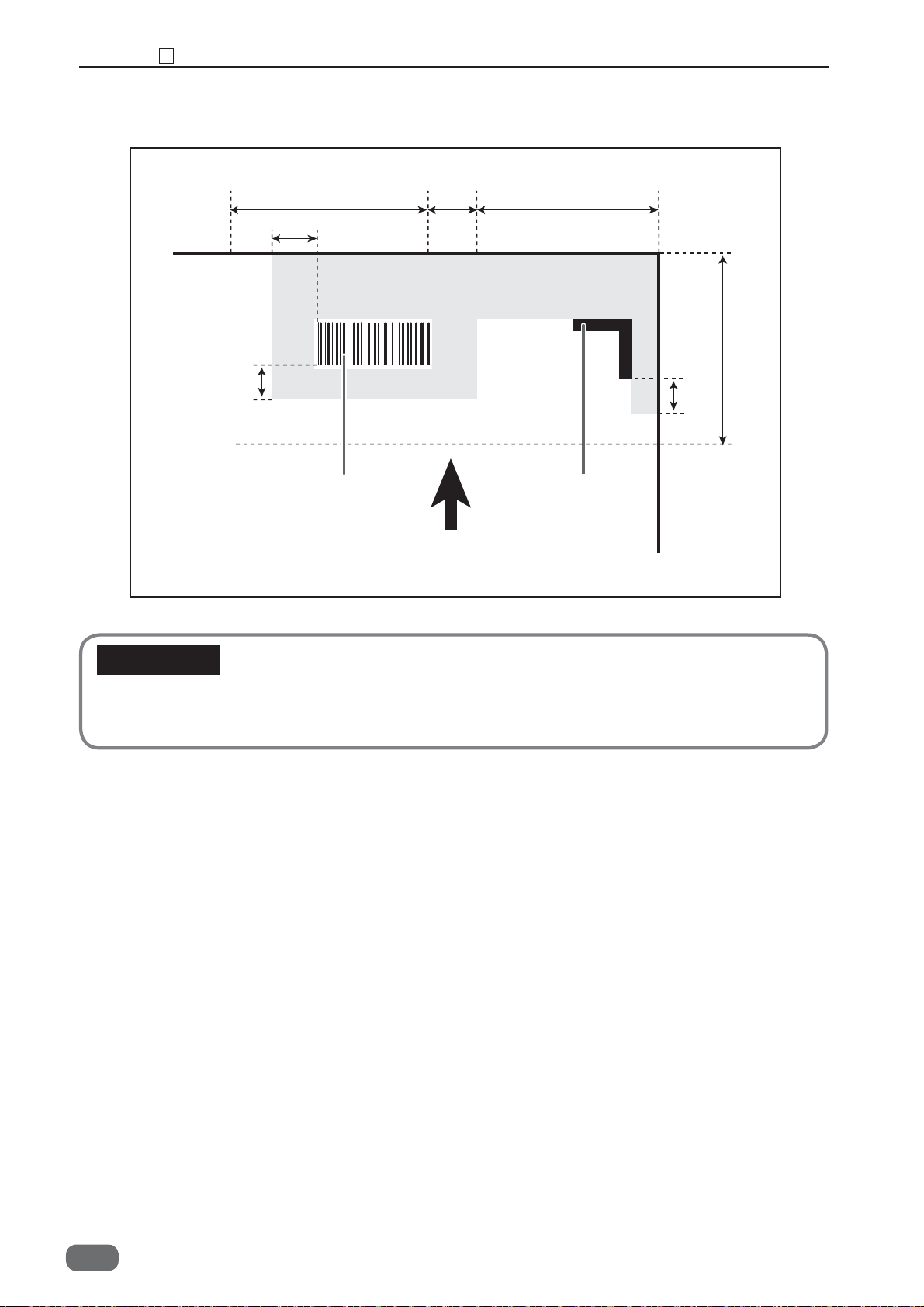
Chapter 2 REG Mark
18
4. Non-printable area for REG marks and barcodes
3 mm or
more
35 mm
3 mm or more
Barcode
5 mm
Non-Printing Area
Paper feed direction
20 mm
20 mm
3 mm
or
more
REG
IMPORTANT
• Any part of the image to be printed shall not enter into the gray-colored area.
• No other printings than REG mark and barcode shall enter into the gray-colored area.
92
W5-Y1030
-0

Chapter 3
Mechanism
1
Exterior
(1) Removing the Feed Cover L
(2) Removing the Upper Cover L
(3) Removing the Feed Cover R
(4) Removing the Upper Cover R
(5) Removing the Under Cover R1
(6) Remove the Under Cover R2
(7) Removing the Under Cover L
(8) Removing the Top Cover 1
(9) Removing the Top Cover 2
(10) Removing the Top Cover 3
(11)
(12)
(13)
2
Paper Feed Section
(1) Removing the Belt Suction Unit
........................................
Removing the Interlock Switches 1-1, 1-2
(SW006, SW007)
Removing the Cover switch, Interlock Switches
2-1, 2-2(SW008, SW009, SW010)
Removing the Interlock Switch 3 (SW011)
..........................
.......................
Removing the Feed Belt
1.
Removing the Suction Solenoid (SL001)
2.
Removing the Feed Belt Driving Motor (MT002)
3.
Removing the suction fan (FM001)
4.
Removing the Paper Level 2 Sensor(SN003)
5.
.....................
.........
.........
.........
........
.......
.........
.........
............
............
.........
..............
......
.....
........
..
.............
....
96
97
97
97
98
98
98
99
99
99
100
100
101
102
104
104
105
105
106
106
107
(2) Removing the Air Blow Duct
Removing the Blow Out Fans 1, 2 (FM002, FM008)
1.
Removing the separate solenoid (SL002)
2.
(3) Removing the Paper Separator Cancel
Switch (SW002)
(4) Removing the Elevator Upper Limit
Switch (SW001)
Removing the Compressor (MT001)
(5)
(6) Removing the SSR (AP001)
Removing the Fuse (FU001,FU002)
(7)
Removing the Paper Level 1 Sensor (SN002)
(8)
(9) Removing the Elevator Lower Limit
Switches 1, 2 (SW003, SW004)
1.
Removing the Elevator Lower Limit Switch1 (SW003)
Removing the Elevator Lower Limit Switch 2 (SW004)
2.
Removing the Elevator Down Switch (SW013)
(10)
(11) Removing the Elevator Motor (MT003)
and Driving Chain
(12)
Removing the Elevator Chain
(on the operator's side)
(13) Removing the Elevator Chain
(on the non-operator's side)
(14)
Removing the PPS1 (SN006, SN007)
........................
........................
......................
.........
.....
............
.....
..........
.....
....
.......
...
....
.114
................
.........
.........
108
109
109
110
110
111
111
111
112
113
113
113
115
116
117
118
3
CAUTION
•Always remove the power cord plug from the outlet before starting work.
•Cautions Regarding Disassembly and Assembly
•In principle, do not operate this machine with parts removed.
•When assembling:
•Unless specifi ed otherwise, perform the disassembly procedure in reverse.
•Make sure that screw types (radius, length) and locations are correct.
•Be sure to use rosette washers when they are specifi ed.
(Rosette washers are used with installation screws to prevent static electricity.)
•To ensure electrical current, a rosette washer is used with the installation screw on
the ground wire. Be sure to use the rosette washer during assembly.

• Photo-Emission Sensor (SN006)
• Photo-Detecting Sensor (SN007)
(15)
Removing the Paper Tray Sensor (SN001)
3
Skew Adjust Section
(1) Removing the Skew Adjust Unit
Removing the Skew Motor (MT004)
1.
(2) Removing PPS2 (SN008, SN009)
2.
Removing the Fan Register (FM005)
3. Removing the Skew Belt
• Photo-Emission Sensor (SN008)
• Photo-Detecting Sensor (SW009)
Double-Feed Detection Section
4
(1) Removing the Double-Feed Detection
Sensor (transmitting side SN005)
(2) Removing the Double-Feed Detection
Sensor (receiving side SN004)
5
CCD Section (option)
(1) Removing the CCD
Removing the PPS3 (SN010, SN011)
(2)
• Photo-Emission Sensor (SN010)
• Photo-detecting sensor (SN011)
Reject Section
6
Removing the Reject Open Motor (MT005)
(1)
Removing the Reject Delivery Module
(2)
Removing the PPS8 (SN015, SN016)
(3)
Removing the Reject HP Sensor (SN012)
(4)
Slot 1 Section (Margin Slitter Section)
7
(1)
Removing the Margin Slitter Module
1. Removing the Margin Slitter 1• 2
(2)
Removing the Slitter Motor 1 (MT007)
Removing the Slitter Motor 2 (MT008)
(3)
(4)
Removing the Slitter 1 HP Sensor (SN037)
Removing the Slitter 2 HP Sensor (SN038)
(5)
Removing the Module Detection 1 (SN024)
(6)
(7)
Removing the PPS4 (SN052, SN053)
• Photo-Emission Sensor (SN052)
• Photo-Detecting Sensor (SN052)
8
Slot 2 Section
(1) Removing the Module
Removing the Slitter Motor 3 (MT009)
(2)
Removing the Slitter Motor 4 (MT010)
(3)
Removing the Jump Motor 1 (MT022)
(4)
Removing the Slitter 3 HP Sensor (SN039)
(5)
Removing the Slitter 4 HP Sensor (SN040)
(6)
(7)
Removing the Module Detection Sensors (2 to 5)
(SN025, SN026, SN027, SN028)
Removing the Jump 1 HP Sensor (SN047)
(8)
...............................
.......................
............
...........
...........
.....................
....................
...........
..............................
...........
...........
...........
...........
...........
.................
...........
...........
...........
...............
....
..
.....
.....
....
..
........
..
.....
....
...
......
........
....
....
..
.......
.......
.......
....
...
.......
.......
........
.
118
118
119
120
120
121
122
122
122
122
123
124
124
125
127
127
127
127
128
129
129
130
133
133
134
134
134
136
136
137
137
138
138
138
139
140
140
140
141
141
142
142
143
144
9
Slot 3 Section
(1)
Removing the Center Slitter Module
1.
Removing the Center Slitters L • R
Removing the Slitter Motor 5 (MT011)
(2)
Removing the Slitter Motor 6 (MT012)
(3)
Removing the Slitter 5 HP Sensor (SN041)
(4)
Removing the Slitter 6 HP Sensor (SN042)
(5)
(6)
Removing the Module Detection Sensors (6 to 9)
(SN029, SN030, SN031, SN032)
Removing the PPS5 (SN054, SN055)
(7)
• Photo-Emission Sensor (SN054)
• Photo-Detecting Sensor (SN055)
10
Slot 4 Section
Removing the Center Slitter Module
(1)
Removing the Slitter Motor 7 (MT013)
(2)
Removing the Slitter Motor 8 (MT014)
(3)
Removing the Slitter 7 HP Sensor (SN043)
(4)
Removing the Slitter 8 HP Sensor (SN044)
(5)
Removing the Module Detection Sensors (10 to 13)
(6)
(SN033, SN034, SN035, SN036)
(7) Removing the PPS6
(SN055, SN056, SN057, SN058)
Photo-Emission Sensors (SN056, SN058)
•
Photo-Detecting Sensors (SN057, SN059)
•
11
Gutter Section
Removing the Gutter Motor 1 (MT015)
(1)
Removing the Gutter Motor 2 (MT015)
(2)
(3)
Removing the Gutter 1 HP Sensor (SN045)
Removing the Gutter 2 HP Sensor (SN046)
(4)
12
Creaser Section
(1) Removing the Creaser Module
(2)
Removing the Creaser Upper Blade Home Position
Sensor (SN019) • Creaser Lower Blade Home Position
Sensor (SN020)
Removing the Creaser Motor (MT019) and the Belt
(3)
(4)
Removing the Creaser Lower Blade Motor (MT020)
Removing the Creaser Encoder Sensor (SN021)
(5)
13
Cutter Section
(1) Removing the Cutter Module
(2)
Removing the Cutter HP 1 Sensor (SN019)
• Cutter HP 2 Sensor (SN020)
Removing the Cutter Motor (MT018) and the Belt
(3)
Removing the Escape Sensors 1, 2 (SN022, SN023)
(4)
Removing the Escape Sensor 1 (SN022)
•
Removing the Escape Sensor 2 (SN023)
•
Removing the Escape Motor (MT017)
(5)
...............................
...............................
..............................
............................
......................................
..............................
....
....
...........
...........
.......
.......
...............
...........
....
...
.............
...........
...........
.......
.......
...............
...
........
.......
...........
...........
......
......
......
......
......
........
..................
.....
.........
.........
...........
..
.
145
145
145
147
148
148
149
149
151
151
151
152
152
152
153
153
154
155
157
157
157
158
158
158
159
159
160
160
160
161
162
162
163
163
163
164
166
166
166
167
94
W5-Y1030
-0

14
Paper Exit Section
(1) Removing the PPS7
•
Photo-Emission Sensors (SN060, SN061, SN062)
Photo-Detecting Sensors (SN063, SN064, SN065)
•
15
Waste Box Section
(1) Removing the Waste Sensors
(SN066, SN067, SN068, SN069)
(2)
Removing the Waste Full Sensor (SN070)
16
Main Drive Section
(1) Removing the Main Motor 1 (MT025)
and the Drive Belt
(2) Removing the Main Motor 2 (MT026)
and the Drive Belt
(3) Removing the Main Motor 3 (MT027)
and the Drive Belt
(4) Removing the Main Motor 4 (MT028)
and the Drive Belt
(5) Removing the Main Motor 5 (MT029)
and the Drive Belt
(6) Removing the Drive Transmission Belt
(Slots 1 to 4)
(7) Removing the Back-Up Roller
(8) Removing the Press Roller
(9) Removing the Driving Roller
(10) Removing the Escape Roller
17
Electrical System Section
(1) Removing the Control Panel
(2) Removing the Main PCB Unit
(3) Removing the EEPROM
(4)
Removing the Slitter Drive PCB Unit .185
(5) Removing the Slitter PCB Unit
(6) Removing the Drive1 PCB Unit
(7) Removing the Drive2 PCB Unit
(8) Removing the Drive 4 PCB Unit
(9) Removing the Relay PCB Unit
(10)
Removing the oscillation PCB Unit
(11) Removing the Receive PCB Unit
(12)
Removing the DC Power Supply Unit (5V)
Removing the DC Power Supply Unit (24V)
(13)
Removing the Cooler Fan 1 (FM004) .192
(14)
Removing the Cooler Fan 2 (FM006) .192
(15)
Removing the Cooler Fan 3 (FM007) .193
(16)
Removing the Contactors 1·2 (AP002, AP003)
(17)
Removing the Emergency Stop Switch (SW018)
(18)
(19) Removing the USB PCB Unit
.........................
...................
.......................
........................
......................
......................
......................
......................
......................
............................
...........
.........
...............
.........
..............
...
.......
.......
.......
.......
......
.....
.....
.....
......
..
..
..
...
......
..
.
.
.
168
168
168
168
170
170
171
172
172
173
174
175
176
177
177
179
180
181
184
184
185
185
186
186
187
188
188
189
189
190
190
194
195
196
3
W5-Y1030
-0
95

Chapter 3 Exterior
1
Exterior
1
Upper cover L
Front cover
Top cover 3 Top cover 1Top cover 2
Feed cover L
Under cover L
Feed cover R
Under cover R1
96
W5-Y1030
Upper cover R
Under cover R2
-0

(1) Removing the Feed Cover L
1. Open the top cover 1.
2. Loosen the four screws, and remove the feed
cover L.
IMPORTANT
• Be sure not to loosen the screw more than nine
times on the cover detachment.
Screw
Chapter 3 Exterior
Screw
Screw
Screw
1
(2) Removing the Upper Cover L
1. Open the top cover 2 and 3.
2. Loosen the three screws, and remove the upper
cover L.
(3) Removing the Feed Cover R
1. Open the top cover 1.
2. Loosen the four screws, and remove the feed
cover R.
IMPORTANT
• Be sure not to loosen the screw more than nine
times on the cover detachment.
3
Screw
Screw
Screw
Screw
Screw
Screw
Screw
W5-Y1030
-0
97

Chapter 3 Exterior
1
(4) Removing the Upper Cover R
1. Open the top covers 2 and 3.
2. Loosen the three screws, and remove the upper
cover R.
(5) Removing the Under Cover R1
1. Take out the fi ve screws, and remove the under
cover R1.
IMPORTANT
• Be sure not to loosen the screw more than nine
times on the cover detachment.
Screw
Screw
Screw
Screw
Screw
Screw
Screw
(6) Remove the Under Cover R2
1. Take out the six screws, and remove the under
cover R2.
IMPORTANT
• Be sure not to loosen the screw more than nine
times on the cover detachment.
Screw
Screw
Screw
Screw
Screw
Screw
Screw
98
W5-Y1030
-0
 Loading...