

Dunkirk ESB0365, ESB3100, ESB4125, ESB4150, ESB5175 Installation Manual And Operating Instructions
...Page 1
EMPIRE STEAM II
OIL-FIRED CAST IRON BOILER
MODEL NUMBERS:
ESB0365 ESB3100.
ESB4125 ESB4150.
ESB5175 ESB5200.
ESB6225 ESB7275
,f
DUNKIRK
85 Middle Road
Dunkirk, NY 14048
Phone (716) 366-5500
Fax. 1716) 366-1209
www. dunkirk corn
An ECR International Brand )C_ f
An ISO 9001-2000 Certified Company
P/N 1305029, Rev ! 0 [08/04]
Page 2
P/N# 1305029, Rev
Safety Symbols and Warnings 2
Ratings, Data, and Dimensions 3
Installation Procedure 4
Ventilation and Combustion Air 5
Connecting Supply and Return Piping Steam 7
Venting System Inspection and Installation 8
Oil Tank and Piping 8
Electrical Wiring 9
Thermostat Operation 9
Normal Sequence of Operation 11
Operating Instructions 11
Maintenance Procedures 14
Replacement Parts List 15
Service Checklist 20
KEEP THIS MANUAL NEAR BOILER j_
RETAIN FOR FUTURE REFERENCE
The following defined symbols are used throughout
this manual to notify the reader of potential hazards
of varying risk levels
ndicates an imminently hazardous situation'_
hich, if not avoided, WILL result in death or I
r!o,s!nj,,y: j
dicates a potentially hazardous situation I
hich, if not avoided, COULD result in death I
serious injury, j/
ndicates a potential hazardous situation I
hich, if not avoided, MAY result in minor or I
oderate injury. It may also be used to alert I
gainst unsafe practices. .t)
1 0 [08/04] • Printed in USA • Made In USA
MPORTANT: Read the following instructlons_
OMPLETELY before mstalhngll
1. Keep boiler area clear and free from com-
bustible materials, gasoline and other flam-
mable vapors and liquids.
2. DO NOT obstruct air openings to the boiler
room.
3. Modification, substitution or elimination of
factory equipped, supplied or specified com-
ponents may result in property damage, per-
sonal injury or the loss of life.
4. TO THE OWNER - Installation and service of
this boiler must be performed by a qualified
installer.
5. TO THE INSTALLER - Leave all instructions
with the boiler for future reference.
6. When this product is installed in the Com-
monwealth of Massachusetts the installation
must be performed by a Licensed Plumber or
_Licensed Gas Fitter.
J
All installations of boilers and venting should
be done only by a qualified expert and in
accordance with the appropriate Pennco
manual. Installing or venting a boiler or any
other gas appliance with improper methods
or materials may result in serious injury or
death due to fire or to asphyxiation from
poisonous gases such as carbon monoxide
which is odorless and invisible.
_.. J
0@
Tested For 15 LBS
ASME
/_,,or kllig Pressure
Page 3

ESB0365 0.65
ESB3100 1.00
ESB4125 1.25
ESB4150 1.50
ESB5175 1.75
ESB5200 2.00
ESB6225 2.25
ESB7275 2.75
NOTES:
78
116
145
170
iiiiiiiii,1_teiaimiiiiiiiiiii!
59
87
109
128
246
363
454
533
wa_er
66 6
101 6
126 7
148 7
iii/iSq_are!iiiil
8x8x15
8x8x15
8x8x15
8x8x15
91 140 .60 80B
140 140 .85 80B
175 140
210 140
245 202 152 633 176 8 8x8x15 140 1.50 80B
280 227 170 708 197 8 8x8x15 140 1.75 70B
315 251 188 783 218.3 8 8x12x15 140 2.00 45B
385 307 230 958 267.1 8 8x12x15 140 2.25 45B
1. Add suffix"T" to denote boiler with tanktess heater•
2. I=B=R burner capacity is based on an oil heating value of 140,000 Btu/gat. and with 13% CO2.
3. Net ratings based on 170°F temperature in radiators and include 33% allowance for normal piping and pick-up toad. Consult manufacturer
for unusual piping and pick-up temperatures•
4. For altitudes above 2,000 ft. ratings maybe reduced at the rate of 4% for every 1,O00 ft. above sea level.
5. No771esizes with an H designation are Hago brand, all others are Delevan.
6. The electrical service is 120 Volts, 15 Amps, 60 Hz.
7. The MEA hum ber for the ESB series is 182-86E.
8. The MEA number for the AFG Beckett Burner used in the ESB series is 213-83-E.
DIMENSIONS (See FIG, A)
ESB-3S 16.375" 6.5" 6.0"
ESB4S 20.25" 8.5" 6.0"
ESB-5S 23.875" 10.25" 7.0"
ESB-6S 27.5" 8.3125" 8.0"
ESB-7S 31.125" 8.3125" 8.0"
TANKLESS WATER HEATER CAPACITIES
ESB0365 0.65 L-24 Available on request 11 8
ESB3100 1.00 L-24 4.5 11 8
ESB4125 1.25 L-24 4.5 13 9
ESB4150 1.50 L-24 4.5 13 9
ESB5175 1.75 L-24 5.0 15 10
ESB5200 2.00 L-24 5.0 15 10
ESB6225 2.25 L-24 5.0 17 11
ESB7275 2.75 L-24 5.0 19 12
A.S.H.E PRESSURE
f_RELZEF VALVE
V u
I FIG. A ]
STANDARD EQUIPMENT: Crated boiler, flush jacket, oil burner, target watt/liner, ASME relief valve, steam
water level gauge, steam pressure gauge, steam pressure control, mechanical low water cut-off, drain
valve, wiring harness, burner electric disconnect, plastic cover, 2" supply tapping, 1½" return tapping, skim
port, and primary control. (NOTE: For tankless heater units, add tankless hot water coil, and 4006 limit
control.)
Page 4
All installations must conform to the requirements of
the authority having jurisdiction. Such applicable
requirements take precedence over the general
instructions of this manual.
Where required by the authority having jurisdiction,
the installation must conform to the American Society
of Mechanical Engineers Safety Code for Controls
and Safety Devices for Automatically Fired Boilers,
ANSI/ASME No. CSD-1.
Locate boiler in front offinat position before removing
crate. Provide a level solid base as near chimney as
possible and centrally located with respect to the
heat distribution system as practical.
Allow 24 inches in the front, top and right hand side
for servicing and cleaning, or removing tankless
water heating coil.
It is recommended that 24 inches be allowed in back
of boiler for convenience when skimming hole is
used.
When installed in a utility room, the door should be
wide enough to allow the largest boiler part to enter,
or to permit replacement of another appliance such
as a water heater.
The boiler shall be installed such that the oil ignition
system components are protected from water
(dripping, spraying, rain etc.) during appliance
operation and service.
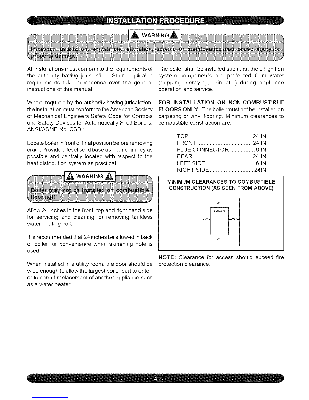
FOR INSTALLATION ON NON-COMBUSTIBLE
FLOORS ONLY- The boiler must not be installed on
carpeting or vinyl flooring. Minimum clearances to
combustible construction are:
TOP ........................................ 24 IN.
FRONT ................................... 24 IN.
FLUE CONNECTOR ................ 9 IN.
REAR ..................................... 24 IN.
LEFT SIDE ............................... 6 IN.
RIGHT SIDE ............................ 241N.
MINIMUM CLEARANCES TO COMBUSTIBLE
CONSTRUCTION (AS SEEN FROM ABOVE)
T
24"
• 6" _24"--
24"
[
NOTE: Clearance for access should exceed fire
protection clearance.
Page 5
COMBUSTIONAIR REQUIREMENTS
(Minimum Opening Requirement)
91,000 19 100 23 46
140,000 28 140 35 70
175,000 35 175 44 88
210,000 42 210 53 106
245,000 49 245 61 122
280,000 56 280 61 140
A space w hose volume is not less than 50 cubic feet per 1000 BTU/Hour of all
appliances installed in that space (cubic feet of space = height x width x length)
** A space w hose volume is less than 50 cubic feet per I000 BTU/Hour of all
appliances installed in that space (cubic feet of space = height x w idth x length)
1. Ventilation of boiler room must be adequate
enough to provide sufficient air to properly support
combustion and venting.
2. When the boiler is located in an unconfined space
in a building of conventional construction frame,
masonry or metal, infiltration normally is adequate to
provide air for combustion and ventilation. However,
in any building which has been altered to conserve
energy or to minimize infiltration, the boiler area
should be considered as a confined space. If there is
anydoubt, install airsuppty provisions for combustion
and ventilation in accordance with section 5.3, Air for
Combustion and Ventilation, of the NFPA 54 1988
code, the recommendations that follow, or applicable
provisions of the local building codes.
3. When the boiler is installed in an unconfined
space, in a building of unusually tight construction,
air for combustion and room ventilation must be
obtained from outdoors or from spaces freely
communicating with the outdoors. A permanent
opening or openings having a total free area of not
less than 1 square inch per 5,000 BTU per hour of
total input rating of att appliances shall be provided.
Ducts may be used to convey make-up air from the
outdoors and shall have the same cross-sectional
area of the openings to which they are connected.
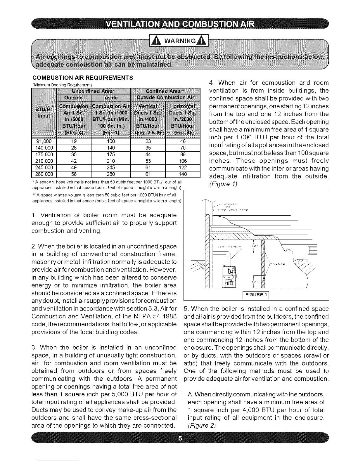
4. When air for combustion and room
ventilation is from inside buildings, the
confined space shall be provided with two
permanent openings, one starting 12 inches
from the top and one 12 inches from the
bottom of the enclosed space. Each opening
shall have a minimum free area of 1 square
inch per 1,000 BTU per hour of the total
input rating ofatl appliances in the enclosed
space, but must not be less than 100 square
inches. These openings must freely
communicate with the interior areas having
adequate infiltration from the outside.
(Figure 1)
J _ i ¸
jl f C_O_NE'_
iL TYr=_ VErsT r_pE
VENf _'i "' E
_J
I FIGURE 1 I
5. When the boiler is installed in a confined space
and atl air is provided from the outdoors, the confined
space shall be provided with two permanent openings,
one commencing within 12 inches from the top and
one commencing 12 inches from the bottom of the
enclosure. The openings shall communicate directly,
or by ducts, with the outdoors or spaces (crawl or
attic) that freely communicate with the outdoors.
One of the following methods must be used to
provide adequate air for ventilation and combustion.
A. When directly communicating with the outdoors,
each opening shall have a minimum free area of
1 square inch per 4,000 BTU per hour of total
input rating of all equipment in the enclosure.
(Figure 2)
Page 6
/
CiUTLET _
AE_
!/ENI PEPE
INLET
AZR
\/ENTZLATZON
LOUVERS FOR
UNIIEATED
CRAWL SPACE
/
I FIGURE 2 1
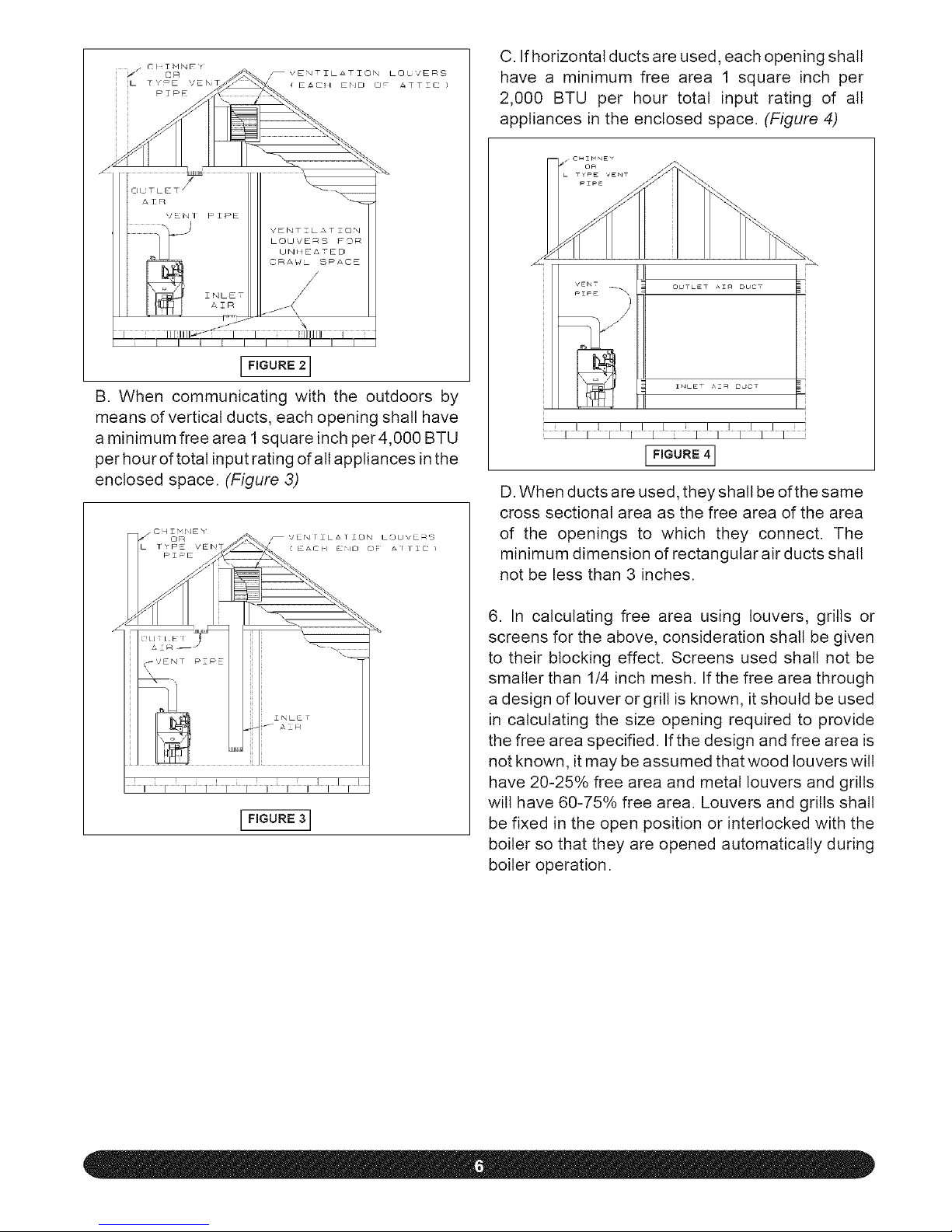
B. When communicating with the outdoors by
means of vertical ducts, each opening shall have
a minimum free area I square inch per4,000 BTU
per hour of totat input rating ofatt appliances inthe
enclosed space. (Figure 3)
I FIGURE 3 I
C. Ifhorizontal ducts are used, each opening shall
have a minimum free area 1 square inch per
2,000 BTU per hour total input rating of all
appliances in the enclosed space. (Figure 4)
VE_S
PIPE \)
/
iJ!llllll![Li_l/ll]llll_ i
D. When ducts are used, they shall be of the same
cross sectional area as the free area of the area
of the openings to which they connect. The
minimum dimension of rectangular air ducts shall
not be less than 3 inches.
6. In calculating free area using louvers, grills or
screens for the above, consideration shall be given
to their blocking effect. Screens used shall not be
smaller than 1/4 inch mesh. If the free area through
a design of louver or grill is known, it should be used
in calculating the size opening required to provide
the free area specified. If the design and free area is
not known, it may be assumed that wood louvers wilt
have 20-25% free area and metal louvers and grills
will have 60-75% free area. Louvers and grills shall
be fixed in the open position or interlocked with the
boiler so that they are opened automatically during
boiler operation.
Page 7

1.Suggestedpipingforsteamheatingsystemcan
beseeninFigure5.Actualpipingmayvarybasedon
systemdesignandlocalconditions.
2. For further piping information refer to the I=B=R
installation piping guide.
3. See Figure 6 for typical piping for domestic hot
water heater.
4. See Figures 7 and 8 for the suggested piping for
a modular steam boiler.
NOTE, B_T_ 3" sUPPLY T_PPING_ _IUST
PI_I.G _UST _E _ MINIMUM OF _". DO NOT
_UCL
I FIGURE 5 I
SUGGESTED PIPING FOR MODULAR STEAM
BOILERS - PUMPED RETURN
I FIGURE 7 I
PIPING FOR BUILT-IN
DOMESTIC HOT WATER HEATER
UNTEMPERED HOT
WATER TO
l AUTOHAT:C WASHER
_N/_M_E_ED
I_ST_LLE_ BELOW CENTE_
COLD WATER IN -_/
IFIGURe: 6 1
SUGGESTED PIPING FOR MODULAR STEAM
BOILERS - GRAVITY RETURN
I FIGURE 8 I
Page 8

Inspect chimney to make certain it is constructed
according to the latest revision of the NFPA 211.
Local regulations may differ from this code and
should be checked. Where there is a conflict, the
local code will prevail.
The boiler must be installed into a chimney which
has a masonry or metallic chimney liner.
An unlined chimney wilt have leaks that wilt cause
poor chimney performance (no draft), and could
result in a positive pressure in the combustion
chamber.
Horizontal portions of the venting system should not
exceed 10 feet in length. Horizontal lengths over 10
ft. will have a negative effect on the chimney
performance.
The chimney should extend at least 2 ft. above any
portion of the building within 10 ft. (Figure 9) It should
produce a -.02 inch W.C. draft in the combustion
chamber. See "Chimney or Vent Sizes" chart for
recommended minimum and maximum chimney or
vent sizes.
Inadequate draft will cause improper combustion,
resulting in dirty flue ways and high fuel bills.
Connect flue pipe same size as boiler outlet to
chimney, sloping upward continuously toward the
chimney approximately 1/4" per foot. Bolt or screw
joints together to avoid sag.
If an oil fired water heater is vented into the same flue
as the boiler, provide a separate hole into the chimney
whenever possible. When this isn't possible, use a
"Y" connection in the flue pipe, using a separate draft
regulator for each unit. When a chimney will not
provide adequate draft to handle the input from the
water heater and boiler simultaneously, wire the
units so that only one wilt operate at a time, favoring
the water heater.
I_,_ NO_E THAN J.O'(3,1 H)
q&o' (3,_ M)
/
HEZGHT ABOVE ANY
_._{ Roo_ GuR_AOEWITHIN
le" C3._ M)
HORIZONTALLY
RIDGE ( .8.f. M) "CHIMNEY 3"
c , 9;2. M ) MIN.
M N. i l
I I GAS VENT OR
TYI_E L VENT 2 '
I i ( . 6,L M MIN.
i 1-t
CHIMNEYOR VENT SIZES
ROUND
BTU/HR INPUT INCHES
MIN MAX
91,,_0"0"140_00_
175,000- 210,000 7 8
iiiiiiiiiiiiiiiiiiiiiiiiiiiiiiiiiiiiiiii r_;
315,000 8 10
SQUARE HEIGHT
INCHES (FT)
MIN I MAX MIN MAX
8x8 I 8x10 15 40
8x8 I 8x12 15 50
Oil tank and piping should be installed in accordance
with the National Board of Fire Underwriters and
local regulations. Oil storage tank, vent, fill pipe and
caps should be as prescribed by local codes. In no
case should the vent pipe be smaller than 1-1/4"
I.P.S. The fill pipe should not be less than 2" I.P.S.
The suction line from the tank to the burner should be
one continuous piece of tubing to prevent air enter-
ing the line. The suction line, must be 3/8" O.D.
copper tubing for runs of 50 feet or less, and 1/2"
O.D. for longer runs. An oil return line, same size as
the suction line, must be used on any installation
where the bottom of the tank is below the fuel unit of
the burner. Oil lines should be buried or otherwise
protected from mechanical injury. Flare fittings on all
oil lines are recommended. Compression fittings on
the suction line often allow air to be drawn into the
fuel pump, making it difficult to maintain oil pressure
at the nozzle. Do not run overhead fuel lines from
tank to oil burner.
Fuel pump connections and by-pass should be made
according to instructions attached to the fuel pump.
Page 9

Iftankis morethan20' fromtheboiler,a twostage
fuel unit shouldbe installedin place of the single
stagepumpsuppliedas standardequipmentwith
theburner.Makecertaintherotationandspeedare
the sameandthe pumpis suitablefor the burner
horsepowerrating.
Anoillinefilterandshut-offvatveshouldbeinstalled
inthesuctionline.Shut-offvatvesshouldbeinstalled
inboththesuctionandreturnlinesattheburnerfor
convenienceinservicingburner.Allowextratubing
atburnersoburnermayberemovedfromboilerfor
cleaningwithoutdisconnectingtubing.(Figures 10-
11) An optional flexible oil line is available.
TYPICAL INSTALLATION -
SINGLE PIPE OIL SYSTEM
IFIGURE101
TYPICAL INSTALLATION -
TWO PIPE OIL SYSTEM
/
_EFER TO LOCAL
CODE
,\
\
[)AHA( [ "1 I Ni¢ltJbl I/'2
1/2 ' O _ COPPER TtJBZrJG
L''G°"E'll
Electrical wiring must conform with the latest revi-
sions of the National Electrical Code, ANSI/NFPA
No. 70, and/or local authority having jurisdiction.
1. When an external electrical source is utilized,
the boiler, when installed, MUST BE electrically
grounded in accordance with these requirements.
2. Install a fused disconnect switch between
boiler and meter at a convenient location.
3. When the boiler is equipped with self-ener-
gized controls, no outside sou rce of electric power
shall be connected to the circuit of this system.
(See "Steam Wiring W/MM #67 Mechanical
LWCO" on next page.)
1. Thermostat should be installed on an inside wall
about four feet above the floor.
2. NEVER install a thermostat on an outside watt.
3. Do not install a thermostat where itwill be affected
by drafts, hot or cold pipes, sunlight, lighting fixtures,
television, fireplaces, or chimneys.
4. Check thermostat operation by raising and lower-
ing thermostat as required to start and stop the
burner.
5. Instructions for the final adjustment of the thermo-
stat are packaged with the thermostat (adjusting
heating anticipator, calibration, etc.).
Page 10

I I
I I
L1 L2
120V
60 HZ
SUPPLY
YELLDW
BLACK
GREEN
WHITE
_URNER
DISCONNECT
LT
#67
LWCO
CAD
CELL
\1/
BURNER
JUNCTION
BOX
R7|84 B 1032
BLACK
DK BLUE
ORANGE
PURPLE
WHITE
BLACK
COMPONENT CODING
Thermostat (Millivolt)
Thermostat (24 Volt)
Thermostat (Line Voltage)
Transformer (120V/24V/40VA)
Transformer (120V/24V/50VA)
Volt Gas Valve
Pressure Switch
OIL BURNER
TRANSFORMER
BLACK
WHITE
Manual Reset Pressure Switch
Control Terminal
Relay Coil
Relay Contacts
Relay Contacts
Limit Switch
Manual Switch
WHITE
SOLENOID
BURNER
MOTOR
Circulator
Energy Cut-Off
Pilot Safety Coil
Wire Connection
Low Water Cut Off
Electric Water Feeder
Power Generator
TI-I --2
WIRING CODE
Line Voltage By Factory
[ : Low Voltage By Factory
Line Voltage By Installer
Low Voltage By Installer
NOTE: Not all components listed are used in all control systems,
Page 11

On a call for heat, the thermostat will actuate, com-
pleting the circuit to the boiler. In turn, the ignition
systems are activated and ignition wilt begin.
In the event of a low water condition, an automatic
low water cut-off device will interrupted power be-
tween the low water cut-off and the burner. The
burner will remain off until the low water condition is
corrected, (i.e., manually restore boiler water or
utilize a water feeder device which wilt automatically
restore water to its normal operating level).
IMPORTANT TO THE INSTALLER - Before putting
the boiler in operation, test the mechanical tow water
cut-off device for proper operation. While burner is
on, open the blow-off valve located in the lower
portion of the cut-off body. This will drain the water
quickly from the cut-off body and break the circuit to
the burner. If it does not, replace control.
The venting system should be inspected at the start
of each heating season. Check the vent pipe from
the boiler to the chimney for signs of deterioration by
rust or sagging joints. Repair if necessary.
Remove the vent pipe at the base of the chimney or
flue and, using a mirror, check for obstruction and
verify compliance to the latest revision of the NFPA
211.
The lever of the pressure relief valve (Figure 12) on
the boiler should be operated periodically to make
sure that it is functioning properly.
i t .......................
( .....
The pressure relief valve should open before the
steam pressure exceeds the 15 lb. reading on the
gauge. If this pressure is exceeded and the pressure
relief valve leaks steam when the boiler is operating
at normal pressures, it should be immediately
replaced. Corrosion can build up rapidly at the valve
seat and prevent its functioning as a safety device.
(See oil burner instructions for nozzle and electrode setting).
DO NOT SET FIRE VISUALLY.
Instruments are the only reliable method to
determine proper air adjustments. An
improperly adjusted burner causes soot and
high fuel bills because of incomplete
combustion of the fuel oil. This in turn may
req uire excessive boiler maintenance, service
costs, and in some instances, house cleaning
or redecorating. A competent service
mechanic should be consulted to make the
proper adjustments with a smoke tester, CO 2
indicator, and draft gauge. NOTE: Bacharach
\0 r Dwyer test kits include these instruments;,
A. Check oil burner nozzle to make certain it is tight
in adapter. Burner mounting bolts should be tight.
B. Check electrode setting, as they may have been
jarred out of position during transportation.
C. Lubricate burner motor if necessary.
Page 12

D. Set roomthermostatto call for heat,or jump
thermostatcontactsontheboilercontrol.
E.Openalloil linevalves.
F.Turnserviceswitchon.Burnershouldstart.
G.On onepipefuel systemsonly,bleedpumpas
soonasburnerstarts.Allowoiltorununtilalltraces
ofair inthesuctionlinedisappear.
H. Turn "OFF"burnerand installpressuregauge
portonpump.
I.Startburneragainandcheckoilpressurefor 140
Ibs.Adjustifnecessary.
A 1/4" diameter slot is provided in the inspection cover plate to take draft readings in the combustion
chamber. (Figure 12) A 1/4" diameter hole will be required in the flue pipe between the boiler and barometric
damper (if used) to take draft, CO2, smoke and temperature readings. Adjust air shutter on oil burner to
obtain a "trace" of smoke. Measure CO 2at this point. Increase air adjustment to lower CO 2approximately
one percent. Check to insure minimum negative .02 w.c., (water column), "overfire" draft and zero smoke.
If -.02 w.c. "overfire" draft can not be maintained, changes and/or modifications may be required in the
venting or the chimney.
The following tables are provided as a guideline for initial start-up. Final adjustments MUST be made using
combustion instruments as previously mentioned.
RIELLO SETTINGS
....._le _ i: N Ai Da_ i ; P_
ESB3100 F-5 3.6 150 PSi 1 .85 80W
ESB4125 F-5 4 150 PSI 3 1.10 60W
ESB4150 F-5 6 150 PSI 4 1.25 60W
ESB5200 F-10 5 150 PSI 0 1.75 80B
CARLI N SETTINGS
ESB3100 EZ-1 0.85 150 PSI .85-1.00 .85 70B
ESB4125 EZ-1 1.00-1.10 150 PSI 1.10-1.25 1.10 70B
ESB4150 EZ-1 1.25-1.35 150 PSI 1.10-1.25 1.25 70B
ESB5200 EZ-2 1.75 150 PSI 1.65-1.75 1.75 70B
BECKETT SETTINGS
ESB3100 AFG 1 5 140 PSi 3-3/8U F3 .85 80B
ESB4125 AFG 1 8 140 PSI 2-3/4" F4 1.10 80B
ESB4150 AFG 2 6 140 PSI 2-3/4" F6 1.25 80B
ESB5200 AFG 5 5 140 PSI 3U F12 1.75 70B H
ESB6225 CF375 4 6 140 PSI L1 N/A 2.00 45B
ESB7275 CF375 4 6 140 PSI L1 N/A 2.25 45B
NOTES:
(1) Model ESB6225 needs a head setting of 1 and ESB7275 needs a head setting of 2.
(2) Nozzle sizes with an H designation are Hago brand, all others are Delevan.
(3) Information in above table uses Beckett model AFG burner for model numbers ESB365-5200 and Beckett
model CF375 for model numbers 6225 and 7275.
IMPORTANT: Check safety control circuit after burner adjustments have been made for satisfactory performance, i)
Page 13

A. Pressure Control- Remove cover and note pressure
setting. With boiler operating, decrease the setting.
When the setting is lower than boiler pressure, the
control will open and turn offthe boiler. After checking
pressure control, reset control to original setting.
B. Mechanical Low Water Cut-off- May be checked
by opening the blow-off valve on the lower portion of
the cut-off body while the boiler is running. This will
drain the water from the boiler and break the circuit
to the burner.
_ WARNING
2. Disconnect power cable at factory supplied burner
electrical disconnect. (Figure 12)
3. Loosen screws on the sides of the lower front
jacket panel. (Figure 6) Pull the bottom part of the
lower front panel forward and lift the lower front panel
up and off the boiler. (Figure 12)
4. Close oil valve (Figures 10-11) and disconnect oit
line from burner.
_MPORTANT: Do not swing door with oil line attached,../)
open
5. Remove nut from swing door stud on right hand
side of door.
Refill boiler to its normal water line.
C. Primary Control and Flame Sensor-
To Check:
1. Flame Failure - simulate by shutting off oil
supply with hand valve while burner is on. Sixty
seconds after flameout, the safety switch locks
out, ignition stops, motor stops and oil valve -
when used - closes. To restart, open oil supply
valve and reset safety switch.
2. Ignition Failure - With burner off, close oil supply
valve and run through start-up procedure, The
safety switch should lock out as in flame failure.
3. Power Failure - Turn off main power supply
switch while burner is operating. When burner
stops, restore power and burner should start. If
operation is not as described as above, check
wiring and controls.
,
Preventative maintenance dan oil fired boiler reduces is
operating costs. The boiler and vent pipe should be
inspected for accumulation of soot or scale deposits 2.
periodically but at least once every year before the start in
d each heating season. When soot is present on the
section walls and flueways, improper combustion will 3.
result, causing additional sooting and scaling until
flueways are completely closed. To remove soot and 4.
scale from the flueways, remove top jacket panel, top
clean-out plate, open burner swing door. (Figure 12)
6. Swing open burner and door to the left. Using a
flue brush, brush the soot and scale into the
combustion space where it can be removed through
the swing door opening.
se caution when vacuuming in the chamber I
tea. Damage to chamber could result, j)
It is recommended to replace the nozzle at the start
of each heating season. Lubricate the burner motor
and circulator motor- if required - with a few drops of
a good grade of light motor oil. Do not over oil. Have
a competent service person service the burner and
check the controls and check the electrodes for
carbon or cracks in the insulators. Burners should be
adjusted to produce the conditions shown in "Startup
and Adjustment of Off Burner."
Swing burner and door to the right until insulation
slightly compressed and the stud is exposed.
Attach nut to the stud and tighten it until the built
stop contacts the mounting door.
Reconnect oil line to burner.
Replace lower jacket panel, and tighten the screws.
5. Connect the power cable at the factory supplied
burner electrical disconnect.
6. Turn on power to boiler and bleed oil line.
1.Turn off power to boiler and allow boiter to coot down.
Page 14

Beforeseasonalstartup it is advisableto havea
competentserviceagencychecktheboilerforsoot
andscaleintheflues,changeoilfilterandnozzle,
cleantheburnerand readjustburnerinputrate to
maintainhighoperatingefficiency.
On steam boilers make certain the boiler is filled to
the water line as indicated in Figure 12. The gauge
cocks should be normally open. To remove dirt from
the gauge glass the petcock may be opened to flush
out the glass.
The radiator valves on a one-pipe steam system
must be either wide open or tightly shut. Do not
attempt to regulate room temperature by partially
closing the radiator valve.
Air vents on steam radiators and the supply main
release air from the system. If radiators do not heat
satisfactorily, make sure the air vents are clean and
operational.
The lever of the pressure relief valve on the boiler
(Figure 12) should be operated periodically to make
sure that it is functioning properly.
The venting system should be inspected at the start
of each heating season. Check the vent pipe from
the boiler to the chimney for signs of deterioration by
rust or sagging joints. Repair if necessary.
Impurities in boiterwater of asteam boiler may cause
foaming and an unsteady water line, or prevent
steam generation. They may result in objectionable
odors escaping from the vents on water boilers. This
condition is caused by oil, grease, and sediment
from pipe fittings collecting within the boiler and can
be remedied only by giving the boiler a thorough
cleaning.
BOILERS SHOULD BE CLEANED BY SKIMMING
OR BLOWING DOWN.
he boiler should not be left unattended dur
_,ing the cleaning process. 1
Some of the impurities in the boiter water will float on
the water and must be skimmed off.
With the boiler empty and cool, slowly begin to add
water. After water has entered boiler - never before
- turn "on" oil burner and adjust water flow so that the
water being added is kept just below boiling point.
Avoid boiling and turbulence.
The safety valve should open before the steam
pressure exceeds the 15 lb. reading on the gauge.
(Figure 12) If this pressure is exceeded and the
safety valve does not open, it must be replaced. Ifthe
safety valve leaks steam when the boiler is operating
at normal pressures, it should be immediately
replaced. Corrosion can build up rapidly at the valve
seat and prevent its functioning as a safety device.
If the water in a steam boiler appears to be dirty or
oily, or the water level in the gauge glass fluctuates
considerably, the boiler should be cleaned. A com-
petent service person will use approved cleaning
compounds and properly clean and flush out the
boiler. He/she should also clean or replace air vents
and traps, clean flue passages and check for proper
operation of all controls and safety devices.
Gradually raise hot water level to skimming hole
(Figure 6) installed on the rear section of the boiler
being careful not to raise it above the opening of the
hole. Skim until there are no impurities. Repeat the
process if necessary.
Water may be checked to make sure it is free from
oil by drawing off a sample at the skimming hole. If
the sample is reasonably free from oil, it will not froth
when boiled on stove. This test does not indicate the
amount of sediment which may lay in the bottom of
the boiler. It is therefore necessary that the boiler be
further cleaned by "blowing down."
Before blowing down the boiler, fill it to the water line.
Turn on burner and allow five pounds of steam
Page 15

pressure to build up. Run a temporary connection
from one of the drain valves to a nearby sewer.
Connect to a drain valve on the opposite end of the
boiler from feed water inlet, if possible. Shut off the
oil burner, open drain valve and blow down the entire
contents of boiler.
Allow boiler to thoroughly cool and slowly refill to water
line. Repeat as many times as required until blow off
water is clear. Owner should blow down boiler at least
once each month d the heating season.
If an exceptional amount of dirt or sludge seems to
be present in the boiler, a boiler cleaning compound
made by a reputable manufacturer may be used
according to the instructions of the manufacturer of
the compound. When any type of cleaning com-
pound is used, care must be taken to thoroughly
flush all traces of the compound out of the boiler.
Following blow down allow the boiler to coot. Add
fresh water slowly. Be certain to blow enough times
as required to remove compounds from system.
The area around the boiler must be kept clear and
free of combustible materials, gasoline and other
flammable vapors and liquids.
The free flow of combustion and ventilation air to the
boiler and boiler room must not be restricted or
blocked.
Periodic inspection and tightening of the tanktess
heater/cover plate bolts will reduce the risk of leaks.
See parts 3 and 5 under "Coil and Cover Plate
Replacement Parts."
Operation should be checked, with burner on, by
opening the blow-off valve located in the lower
portion of the low water cut-off body. This will drain
the water quickly from the cut-off body and break the
circuit to the burner. If it does not, replace the control.
During the heating season, the blow-off valve on the
low water cut-off should be opened once a week to
flush out the sediment chamber so the device will be
free to function properly. (Figure 12) Use a pail to
catch the discharge.
It is suggested that a qualified service agency be
employed to make an annual inspection of the boiler
and heating system. They are experienced in mak-
ing the inspections outlined above and, in the event
repairs or corrections are necessary, can make the
proper changes for safe operation of the boiler.
\
\
/
1 HW-012.02 Bolt - 7/16-14x1½ Square Head 8
2 252-2-2.00 Gasket - B Tankless 1
3 202-2-1.00 Cowr Plate - B Tankless Coil 1
4 HW-013.01 Nut 7/16-14 Square 8
5 252-3-1.02 Tankless Coil L-24 1
6 &Q-020.03 Well ¾ x 1½ - 123870A 1
7 275-1-1.00 Harness 1
8 &Q-008.00 Control - L4006A1827 1
Page 16

3
/
/
5
TO BURNER
\
\
6
1
2
3
4
5
6
7
8
9
10
11
12
* This
PF05501
GA-003.00
GA-004.00
PF-025.01
PF-026.05
WC-011.00
275-2-3.01
753-1-3.00
28511301
28511201
SS-001.01
1263012
28511801
1263013
1263011
28511901
Pipe Fit - Nipple ½" x 2" Brass 2
Gauge Pressure (Steam) 1
Gauge - Water Level 1
Pipe Fit Tee 1/4" 1
Pipe Fit Nipple ½" x 3" 1
MLWCO #67-CH-3 24 Volt 1
LWCO Assembly Steam* 1
Siphon 90° Black Iron 1
Harness ELWCO 24" 1
Harness Pressure Switch 30" 1
Pressure Switch PA404A-1009 1
Harness Bumer 22" (Beckett & RieIIo) 1
Harness Aquastat 41" (Carlin)
Burner Hamess 8" (Beckett)
Burner Hamess 8" (Riello) 1
Burner Harness 8" (Carlin)
includes MLWCO #2, 4, 5, 7, 8, 9, & 10
8
"%
:3 ,--8
-i0
1 VR-002.02 Relief Val_ #15 ¾ 1
2 PF-019.02 Pipe Fit Coupling ¾" 1
3 PF-005.01 Pipe Fit Npl ¾ Close 1
4 HW06701 Stud 5/16-18 x 2-3/8 4
5 2252501 Support - Jacket Brkt 2
6 HW07001 Stud 5/16" x 18x 1-3/8" 3
7 HW06901 Nut 5/16"-18 Wislock 8
8 HW-016.02 Drain 1
9 PF-004.04 Pipe Fit Bushing 1!¼x ¾ 1
2452906 Flue Collector - 3 Sec.
2452902 Flue Collector - 4 Sec.
10 2452903 Flue Collector - 5 Sec. 1
2452907 Flue Collector - 6 Sec.
2452908 Flue Collector - 7 Sec.
Page 17

P
!
@
10 11
1 !00-5-10.0! Rear Section !
#60 Push Nipple - 3 Sec. 2
#60 Push Nipple - 4 Sec. 3 9
2 !00-!-8.01 #60 Push Nipple - 5 Sec. 4
#60 Push Nipple - 6 Sec. 5
#60 Push Nipple - 7 Sec. 6 10
Center Section - 3 Sec. 1 1!
Center Section - 4 Sec. 2
3 1005110! Center Section - 5 Sec. 3
Center Section - 6 Sec. 4 10022201
Center Section - 7 Sec. 5 10022202
4 10051202 Front Section Castover 1 10022203
5 5611508 Kit -Target Wall & Insulation Blanket 1 10022207
6 25511005 Insul Blanket !6x24 (6 & 7 Section) 1 10022208
HW-025.05 Tie Rod ½ x 9 - 3 Sec. 10022204
HW-025.01 Tie Rod ½ x !2½ - 4 Sec. 10022205
7 HW-025.02 Tie Rod ½ x !6½ - 5 Sec. 3 10022206
HW-025.03 Tie Rod ½ x 20½ - 6 Sec. 10022209
HW-025.09 Tie Rod ½ x 23½ - 7 Sec. 10022210
#22 Push Nipple - 3 Sec. 2
#22 Push Nipple - 4 Sec. 3
8 100-1-5.01 #22 Push Nipple - 5 Sec. 4
#22 Push Nipple - 6 Sec. 5
#22 Push Nipple - 7 Sec. 6
i ..iiii
Rope, Med. Density - 3 Sec.
Rope, Med. Density - 4 Sec.
MS-006.00 Rope, Med. Density - 5 Sec.
Rope, Med. Density - 6 Sec.
Rope, Med. Density - 7 Sec.
HW-008.03 Washer ½ ID Flat
HW-003.05 Nut ½-13 Hex Head
13.0'
19.5'
26.0'
32.5'
39.0'
3
3
3 Section Without Coil
4 Section Without Coil
5 Section Without Coil
6 Section Without Coil
7 Section Without Coil
3 Section With Tankless Coil
4 Section With Tankless Coil
5 Section With Tankless Coil
6 Section With Tankless Coil
7 Section With Tankless Coil
Page 18

7
\
\
\
\
/
1
21522801 Top Panel - 3 Sec.
21522802 Top Panel - 4 Sec.
1 21522803 Top Panel - 5 Sec. 1
21522806 Top Panel - 6 Sec.
21522807 Top Panel - 7 Sec,
2 21521501 Rear Panel 1
21523101 Right Side Panel - 3 Sec.
21523102 Right Side Panel - 4 Sec.
3 21523103 Right Side Panel - 5 Sec. 1
21523104 Right Side Panel - 6 Sec.
21523105 Right Side Panel - 7 Sec.
4 21524401 Lower Cowl - Right 1
5 21524301 Lower Cowl - Left 1
6 21524101 Top Front Panel 1
21521803 Left Side Panel - 3 Sec.
21521804 Left Side Panel - 4 Sec.
21521805 Left Side Panel - 5 Sec. 1
21521806 Left Side Panel - 6 Sec.
21521807 Left Side Panel - 7 Sec.
?
7
1 2552901 Mounting Door Insulation & Plug 1
la 2551901 Door Plug Replacement 1
2 HW-005,01 Screw t¼-20x½ Self-Tapping 2
3 10011701 Observation Door 1
4 25511101 Obs, Door Gasket 1
5 HW06801 t¼ x 1¾ Drive Lock Pin 2
6 10011501 Swing Door 1
7 HW06701 5/16 x 18 x2-3/8 Stud 1
Insulation - Swing Door (Carlin &
2553301
8 Riello Burners) 1
Insulation - Swing Door (Beckett
2553303
AFG Burners)
9 10011301 Mounting Door 1
Page 19

iiiiiiiiii,i'iii ; iJ,i;il;il;i;2ii.iiiiiiililiii ; ;ii;i!Lii i iiiii`i` `i` ii;ii ii;ii ii;ii ii;ii ii;ii ii;ii ii;ii ii;ii ii;ii ii;ii ii;ii ii;ii ii;ii ii;ii ii;ii ii;ii ii;ii ii;ii ii;ii i`i !i !i! i ii;i! i i!ii iii! i iii!ii iii! i iii!ii iii! i iii!ii iii! i iii!ii iii! i iii!ii iii! i iii!ii iii! i iii!iiELii i iiiii`i` ` i;iiiiiii i` `ii
BN04002 Burner Oil UT902 Beckett (ESB3100)
2
3
4
BN04003 Burner Oil
BN04004 Burner Oil
BN04006 Burner Oil
BN08901 Burner Oil
30A064202 Burner Oil
BN07007 Burner Oil
BN08401 Burner Oil
BN08402 Burner Oil
BN08403 Burner Oil
UT903 Beckett (ESB4125)
UT904 Beckett (ESB4150)
UT906 Beckett (ESB5200)
UT1801 Beckett (ESB6225, ESB7275)
Riello 40/F5 (ESB3100, ESB4125, ESB4150)
Riello 40/F10 (ESB5200)
Caflin EZ-1 (ESB3100)
Caflin EZ-1 (ESB4125, ESB4150)
Caflin EZ-2 (ESB5200)
BN08001
CD-001.01
RY00701
1320004
1320006
NZ-002.10
NZ00206
NZ01201
14619346
NZ00802
1320012
NZ00804
NZ00206
1320002
1320010
NZ00904
NZ00905
Burner Oil Flange Gasket #3616
Cad Cell (For Boilers w/Beckett Burners Only)
Control R7184B 1032 (7456U) (For Boilers w/Beckett
Burners Only)
Nozzle .85 80B (ESB3100 Beckett)
Nozzle 1.10 80B (ESB4125 Beckett)
Nozzle 1.25 80B (ESB4150 Beckett)
Nozzle 1.75 80B (ESB5200 Beckett)
Nozzle 2.00 45B (ESB6225 Beckett)
Nozzle 2.25 45B (ESB7275 Beckett)
Nozzle .85 80W (ESB3100 Riello)
Nozzle 1.10 60W (ESB4125 Riello)
Nozzle 1.25 60W (ESB4150 Riello)
Nozzle 1.75 80B (ESB5200 Riello)
Nozzle .85 70B (ESB3100 Caflin)
Nozzle 1.10 70B (ESB4125 Caflin)
Nozzle 1.25 70B (ESB4150 Caflin)
Nozzle 1.75 70B (ESB5200 Caflin)
1
1
1
AFG BURNER PARTS
(Used on all boiler models with Beckett Burners except ESB6225and ESB7275
_RT_ ;DE_RI_
1 RP03801 Blast Tube AFG
RP03701 Fuel Pump, 2 Stage, 140 PSI, AFG
2
RP03702 Fuel Pump, 1 Stage, 140 PSI, AFG
3 BN07102 Drawer Assembly (Oil Line), AFG
4 BN08001 Burner Gasket
5 RP-015.00 Motor
6 RP-019.01 Transformer
BECKETT CF375 BURNER PARTS
(Used on n_dels ESB6225 and ESB7275)
PART N_ DES _RI_ i_1'4 t ....
1 RP04501 Fuel Pump, Cleancut (21844U)
2 RP-015.00 Motor, PSC (21805U)
3 RP02001 Transformer (51771U)
4 RP04601 Oil Burner Valve Coil Kit (21755U)
Page 20

Inspect Chimney and Flue Pipe [ X ]
Inspect and Clean Appliance [ X ]
Inspect Oil Line - Size/Leaks [ X ]
Inspect Electrical Connections [ X ]
Install New Filter [ X ]
Room Make-up Air [ X ]
Electrode Setting [ X ]
Proper Light-Off (Hot & Cold) [ X ]
Controls and Safety Devices [ X ]
Nozzle-Size, Angle, Type [ * ]
Pump PressureNacuum [ * ]
Line Voltage/Motor Amps [ * ]
Smoke Test [ * ]
Draft-Overfire/In Flue [ * ]
CO2or 0 2 [ * ]
Flue Gas Temperature [ * ]
* Measure with instruments and record results
below.
 Loading...