

Page 1
CONTROL MODULE
REPLACEMENT KIT #550002965
INSTRUCTIONS
CHB-100, CHB-130 and CCB-150
Kit installation shall be completed by qualied agency.
WARNING
!
Fire, explosion, asphyxiation and electrical shock hazard.
Improper installation could result in death or serious injury.
Read this instruction and understand all requirements,
including requirements of authority having jurisdiction,
before beginning installation. Installation not complete until
appliance operation veried per Installation, Operation &
Maintenance Manual provided with boiler.
1.
Follow instructions TO TURN OFF GAS TO APPLIANCE
found in Installation, Operation & Maintenance Manual.
Verify all electrical power to boiler is turned off.
WARNING
!
Electrical shock hazard. Turn OFF electrical power supply at
service panel.
2.
Remove front jacket casing per instructions found in
Installation, Operation & Maintenance Manual.
WARNING
!
Burn hazard. Verify heat exchanger has cooled or use
appropriate personal protection equipment.
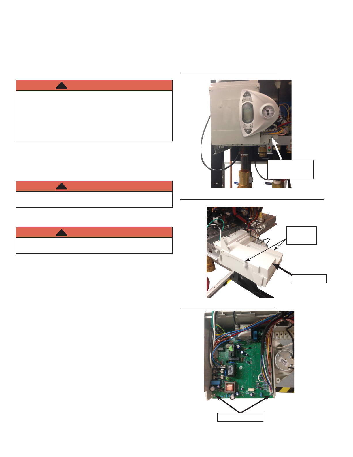
Figure 1 - Control Housing Screw
Control Housing
Screw
Figure 2 - Control Housing Folded Down on Hinge
Back Cover
Screws
3.
Remove control housing screw on lower right of control
housing. See gure 1.
4.
Slide control housing forward, it will fold down on its
built in hinge. See gure 2
5.
Remove two back cover screws. Remove back cover.
See gure 2.
6.
Disconnect all wiring connectors on control board. See
gure 3.
7.
Remove 2 screws holding board in place. Slide board
out. See gure 3.
8.
Replace board with new board, screw board in place.
Connect wiring connectors on control board. See gure 3.
9.
Replace back cover.
10.
Fold control housing up and slide back into position.
Secure with control housing screw. See gure 1.
Back Cover
Figure 3 - Screws Holding Board
Board Screws
P/N 240010533, Rev. A [07/2014]
Page 2
CONTROL BOARD REPLACEMENT KIT
11.
Remove any call for heat or hot water.
12.
Turn gas and electric power ON.
13.
Power up boiler.
14.
Congure control for proper boiler size and type.
15.
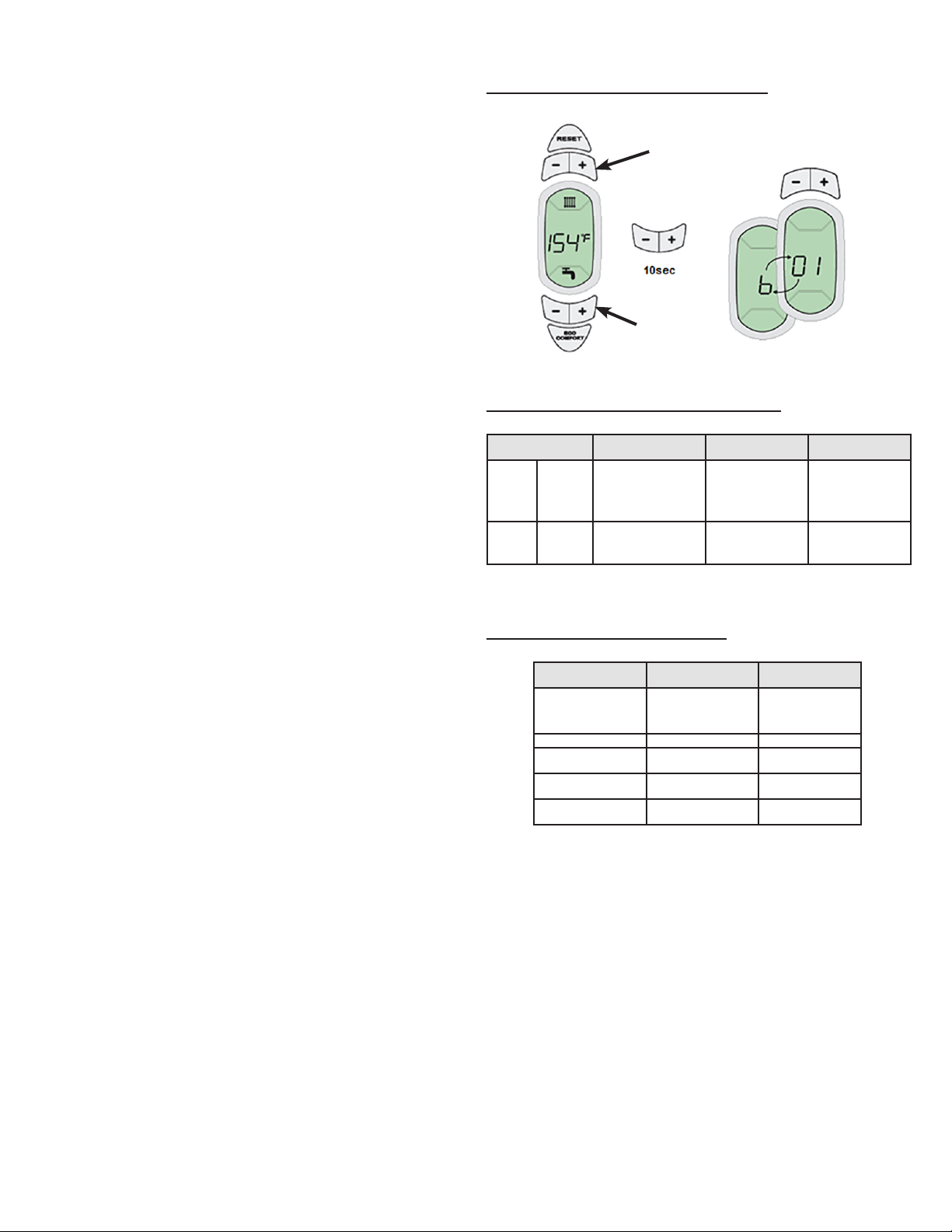
To access the Parameter “tS” menu:
• Press and hold Reset button for 10 seconds, display
will read “tS”, release button.
• Press the Reset button for 1 second, display will read
“P01”.
• Press Heating buttons to scroll the list of parameters.
Press DFHW buttons to view or change a parameter.
Two Parameters need to be set “P01 & P02” as shown
in gure 4.
16.
To access Conguration menu:
• Press DHW + & - (both) buttons and hold for 10
seconds; “b01” will appear ashing.
• Press Heating buttons to scroll Conguration list.
Press DHW buttons to view or change a setting.
Figure 4 - Enter Conguration Menu
CH
DHW
Figure 4 - Enter Parameter "tS" Menu
tS Menu CCB-150 CHB-100 CHB-130
P01
P02
Gas
Type
Boiler
Type
0=Natural
Gas; 1=LP
Gas
1 2 2
0=Natural
Gas; 1=LP
Gas
0=Natural
Gas; 1=LP
Gas
• Conguration “b01” is only one to be changed per
chart in Figure 6.
• When proper size is selected, press and hold DHW
+ & - (both) buttons for 10 seconds to exit, or turn
power off then on, or wait two minutes for auto exit.
• Boiler is now ready for operation
17.
Verify proper operation by following START UP
PROCEDURE in Installation, Operation & Maintenance
Manual.
18.
Install front jacket casing following instructions found in
Installation & Maintenance Manual.
Figure 6 - Proper Size Settings
Parameter Description Setting
b01
b01
b01
b01
Curve
Selection
CHB-100 0
CHB-130 1
CCB-150 2
Default =2
 Loading...